CN102902261A - Computing device and methods of presenting data to identify faults within power systems - Google Patents
Computing device and methods of presenting data to identify faults within power systems Download PDFInfo
- Publication number
- CN102902261A CN102902261A CN2012102623703A CN201210262370A CN102902261A CN 102902261 A CN102902261 A CN 102902261A CN 2012102623703 A CN2012102623703 A CN 2012102623703A CN 201210262370 A CN201210262370 A CN 201210262370A CN 102902261 A CN102902261 A CN 102902261A
- Authority
- CN
- China
- Prior art keywords
- user
- data
- fault
- oblatio
- calculation element
- Prior art date
- Legal status (The legal status is an assumption and is not a legal conclusion. Google has not performed a legal analysis and makes no representation as to the accuracy of the status listed.)
- Pending
Links
Images


Classifications
-
- G—PHYSICS
- G05—CONTROLLING; REGULATING
- G05B—CONTROL OR REGULATING SYSTEMS IN GENERAL; FUNCTIONAL ELEMENTS OF SUCH SYSTEMS; MONITORING OR TESTING ARRANGEMENTS FOR SUCH SYSTEMS OR ELEMENTS
- G05B23/00—Testing or monitoring of control systems or parts thereof
- G05B23/02—Electric testing or monitoring
- G05B23/0205—Electric testing or monitoring by means of a monitoring system capable of detecting and responding to faults
- G05B23/0259—Electric testing or monitoring by means of a monitoring system capable of detecting and responding to faults characterized by the response to fault detection
- G05B23/0267—Fault communication, e.g. human machine interface [HMI]
-
- H—ELECTRICITY
- H02—GENERATION; CONVERSION OR DISTRIBUTION OF ELECTRIC POWER
- H02J—CIRCUIT ARRANGEMENTS OR SYSTEMS FOR SUPPLYING OR DISTRIBUTING ELECTRIC POWER; SYSTEMS FOR STORING ELECTRIC ENERGY
- H02J13/00—Circuit arrangements for providing remote indication of network conditions, e.g. an instantaneous record of the open or closed condition of each circuitbreaker in the network; Circuit arrangements for providing remote control of switching means in a power distribution network, e.g. switching in and out of current consumers by using a pulse code signal carried by the network
- H02J13/00001—Circuit arrangements for providing remote indication of network conditions, e.g. an instantaneous record of the open or closed condition of each circuitbreaker in the network; Circuit arrangements for providing remote control of switching means in a power distribution network, e.g. switching in and out of current consumers by using a pulse code signal carried by the network characterised by the display of information or by user interaction, e.g. supervisory control and data acquisition systems [SCADA] or graphical user interfaces [GUI]
-
- H—ELECTRICITY
- H02—GENERATION; CONVERSION OR DISTRIBUTION OF ELECTRIC POWER
- H02J—CIRCUIT ARRANGEMENTS OR SYSTEMS FOR SUPPLYING OR DISTRIBUTING ELECTRIC POWER; SYSTEMS FOR STORING ELECTRIC ENERGY
- H02J13/00—Circuit arrangements for providing remote indication of network conditions, e.g. an instantaneous record of the open or closed condition of each circuitbreaker in the network; Circuit arrangements for providing remote control of switching means in a power distribution network, e.g. switching in and out of current consumers by using a pulse code signal carried by the network
- H02J13/00002—Circuit arrangements for providing remote indication of network conditions, e.g. an instantaneous record of the open or closed condition of each circuitbreaker in the network; Circuit arrangements for providing remote control of switching means in a power distribution network, e.g. switching in and out of current consumers by using a pulse code signal carried by the network characterised by monitoring
-
- Y—GENERAL TAGGING OF NEW TECHNOLOGICAL DEVELOPMENTS; GENERAL TAGGING OF CROSS-SECTIONAL TECHNOLOGIES SPANNING OVER SEVERAL SECTIONS OF THE IPC; TECHNICAL SUBJECTS COVERED BY FORMER USPC CROSS-REFERENCE ART COLLECTIONS [XRACs] AND DIGESTS
- Y02—TECHNOLOGIES OR APPLICATIONS FOR MITIGATION OR ADAPTATION AGAINST CLIMATE CHANGE
- Y02B—CLIMATE CHANGE MITIGATION TECHNOLOGIES RELATED TO BUILDINGS, e.g. HOUSING, HOUSE APPLIANCES OR RELATED END-USER APPLICATIONS
- Y02B90/00—Enabling technologies or technologies with a potential or indirect contribution to GHG emissions mitigation
- Y02B90/20—Smart grids as enabling technology in buildings sector
-
- Y—GENERAL TAGGING OF NEW TECHNOLOGICAL DEVELOPMENTS; GENERAL TAGGING OF CROSS-SECTIONAL TECHNOLOGIES SPANNING OVER SEVERAL SECTIONS OF THE IPC; TECHNICAL SUBJECTS COVERED BY FORMER USPC CROSS-REFERENCE ART COLLECTIONS [XRACs] AND DIGESTS
- Y02—TECHNOLOGIES OR APPLICATIONS FOR MITIGATION OR ADAPTATION AGAINST CLIMATE CHANGE
- Y02E—REDUCTION OF GREENHOUSE GAS [GHG] EMISSIONS, RELATED TO ENERGY GENERATION, TRANSMISSION OR DISTRIBUTION
- Y02E60/00—Enabling technologies; Technologies with a potential or indirect contribution to GHG emissions mitigation
-
- Y—GENERAL TAGGING OF NEW TECHNOLOGICAL DEVELOPMENTS; GENERAL TAGGING OF CROSS-SECTIONAL TECHNOLOGIES SPANNING OVER SEVERAL SECTIONS OF THE IPC; TECHNICAL SUBJECTS COVERED BY FORMER USPC CROSS-REFERENCE ART COLLECTIONS [XRACs] AND DIGESTS
- Y04—INFORMATION OR COMMUNICATION TECHNOLOGIES HAVING AN IMPACT ON OTHER TECHNOLOGY AREAS
- Y04S—SYSTEMS INTEGRATING TECHNOLOGIES RELATED TO POWER NETWORK OPERATION, COMMUNICATION OR INFORMATION TECHNOLOGIES FOR IMPROVING THE ELECTRICAL POWER GENERATION, TRANSMISSION, DISTRIBUTION, MANAGEMENT OR USAGE, i.e. SMART GRIDS
- Y04S10/00—Systems supporting electrical power generation, transmission or distribution
- Y04S10/30—State monitoring, e.g. fault, temperature monitoring, insulator monitoring, corona discharge
-
- Y—GENERAL TAGGING OF NEW TECHNOLOGICAL DEVELOPMENTS; GENERAL TAGGING OF CROSS-SECTIONAL TECHNOLOGIES SPANNING OVER SEVERAL SECTIONS OF THE IPC; TECHNICAL SUBJECTS COVERED BY FORMER USPC CROSS-REFERENCE ART COLLECTIONS [XRACs] AND DIGESTS
- Y04—INFORMATION OR COMMUNICATION TECHNOLOGIES HAVING AN IMPACT ON OTHER TECHNOLOGY AREAS
- Y04S—SYSTEMS INTEGRATING TECHNOLOGIES RELATED TO POWER NETWORK OPERATION, COMMUNICATION OR INFORMATION TECHNOLOGIES FOR IMPROVING THE ELECTRICAL POWER GENERATION, TRANSMISSION, DISTRIBUTION, MANAGEMENT OR USAGE, i.e. SMART GRIDS
- Y04S10/00—Systems supporting electrical power generation, transmission or distribution
- Y04S10/40—Display of information, e.g. of data or controls
-
- Y—GENERAL TAGGING OF NEW TECHNOLOGICAL DEVELOPMENTS; GENERAL TAGGING OF CROSS-SECTIONAL TECHNOLOGIES SPANNING OVER SEVERAL SECTIONS OF THE IPC; TECHNICAL SUBJECTS COVERED BY FORMER USPC CROSS-REFERENCE ART COLLECTIONS [XRACs] AND DIGESTS
- Y04—INFORMATION OR COMMUNICATION TECHNOLOGIES HAVING AN IMPACT ON OTHER TECHNOLOGY AREAS
- Y04S—SYSTEMS INTEGRATING TECHNOLOGIES RELATED TO POWER NETWORK OPERATION, COMMUNICATION OR INFORMATION TECHNOLOGIES FOR IMPROVING THE ELECTRICAL POWER GENERATION, TRANSMISSION, DISTRIBUTION, MANAGEMENT OR USAGE, i.e. SMART GRIDS
- Y04S10/00—Systems supporting electrical power generation, transmission or distribution
- Y04S10/50—Systems or methods supporting the power network operation or management, involving a certain degree of interaction with the load-side end user applications
- Y04S10/52—Outage or fault management, e.g. fault detection or location
-
- Y—GENERAL TAGGING OF NEW TECHNOLOGICAL DEVELOPMENTS; GENERAL TAGGING OF CROSS-SECTIONAL TECHNOLOGIES SPANNING OVER SEVERAL SECTIONS OF THE IPC; TECHNICAL SUBJECTS COVERED BY FORMER USPC CROSS-REFERENCE ART COLLECTIONS [XRACs] AND DIGESTS
- Y04—INFORMATION OR COMMUNICATION TECHNOLOGIES HAVING AN IMPACT ON OTHER TECHNOLOGY AREAS
- Y04S—SYSTEMS INTEGRATING TECHNOLOGIES RELATED TO POWER NETWORK OPERATION, COMMUNICATION OR INFORMATION TECHNOLOGIES FOR IMPROVING THE ELECTRICAL POWER GENERATION, TRANSMISSION, DISTRIBUTION, MANAGEMENT OR USAGE, i.e. SMART GRIDS
- Y04S20/00—Management or operation of end-user stationary applications or the last stages of power distribution; Controlling, monitoring or operating thereof
Landscapes
- Engineering & Computer Science (AREA)
- Human Computer Interaction (AREA)
- Power Engineering (AREA)
- Physics & Mathematics (AREA)
- General Physics & Mathematics (AREA)
- Automation & Control Theory (AREA)
- Remote Monitoring And Control Of Power-Distribution Networks (AREA)
- Testing Of Devices, Machine Parts, Or Other Structures Thereof (AREA)
- Testing And Monitoring For Control Systems (AREA)
- Measurement Of Mechanical Vibrations Or Ultrasonic Waves (AREA)
Abstract
A computing device (112) for use with a power system (100) is provided. The computing device includes a processor (214) that is programmed to organize data representative of at least one fault within the power system and to generate a graphical representation of the organized data. The computing device also includes a presentation interface (208) that is coupled to the processor for presenting the graphical representation to a user to enable the user to identify the fault. Moreover, a user interface (204) is coupled to the presentation interface and configured to enable the user to select at least one data point on the graphical representation such that the user is enabled to identify at least one variable of the fault.
Description
Technical field
The field of the invention relates generally to electric system, and more specifically, relates to for the electric power system with the oblatio data to the user so that this user can identify the calculation element of fault and/or the variable relevant with the fault in the electric system.
Background technology
At least some known electric power system envelope are the machine of turbine for example.For example the machine of turbine can comprise for example assembly of bearing, gear and/or axle.Such assembly can wear and tear in time, causes for example splitting and/or out-of-alignment fault of this assembly.The continuation of the out of order wear assembly of apparatus operation can cause the additional injuries of other assemblies and/or can cause the premature failure of this assembly and/or interconnected system.
For the damage of the assembly in the detection machine, with at least some known machine of monitoring system continuous monitoring.At least some known monitoring systems come the degree of approach of at least some assemblies of detection system to measure with sensor.The degree of approach is measured and can be carried out with eddy current sensor, magnetic sound pickup sensor, microwave remote sensor and/or capacitive sensor.The data that detected by such sensor send display device and/or calculation element to for analyzing, and the output of this analysiss is for making the user can identify the interior any fault of electric system.Such data can comprise to be measured and/or multiple variable, and it is concluded and/or contrasts determines whether fault is arranged in the power system.
Yet, in known monitoring system, the last diagnostic of general only system by oblatio to the user.The notice that for example, can only exist in machine to user's oblatio fault.As a result, the user may not see actual measurement and/or the variable that promotes fault diagnosis.For example, the user may be not be adopted the data of graphical format by oblatio, and it makes actual measurement and/or variable that the user can recognition detection.Known calculation element and/or display device can not provide interaction platform to the user, and it makes the user can select multiple measurement and/or variable for further considering.
Summary of the invention
In one embodiment, provide calculation element for the electric power system.This calculation element comprises processor, and it is programmed to organize the data that represent at least one fault in this electric system, and generates the diagrammatic representation of the data of this tissue.This calculation element also comprises the oblatio interface, and it is coupled to this processor and is used for this diagrammatic representation oblatio to the user so that this user can identify this fault.In addition, user interface is coupled to this oblatio interface and is configured to make this user to select at least one data point in this diagrammatic representation, so that this user can identify at least one variable of this fault.
In another embodiment, provide electric system.This electric system comprises at least one machine with at least one assembly and near at least one sensor of this component placement.This sensor is configured to detect at least one fault in this assembly.This electric system also comprises the calculation element that is coupled to this sensor.This calculation element comprises processor, and it is programmed to organize the data that represent this fault, and generates the diagrammatic representation of these data.In addition, this calculation element comprises the oblatio interface, and it is coupled to this processor and is used for this diagrammatic representation oblatio to the user so that this user can identify this fault.User interface is coupled to this oblatio interface and is configured to make this user to select at least one data point in this diagrammatic representation, so that this user can identify at least one variable of this fault.
In yet another embodiment, provide the oblatio data to identify the method for the fault in the electric system.The data communication device that represents at least one fault in this electric system is crossed processor and is organized.Generated the diagrammatic representation of these data by this processor.This diagrammatic representation via oblatio interface oblatio to the user so that this user can identify this fault.In addition, make this user select at least one data point in this diagrammatic representation via user interface, so that this user can identify at least one variable of this fault.
Description of drawings
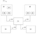
Fig. 1 is the block diagram of exemplary electric system;
Fig. 2 be can with the block diagram for the exemplary calculated device of electric power system shown in Fig. 1;
Fig. 3 is the graphics view of the exemplary output that can be generated by the calculation element shown in Fig. 2; And
Fig. 4 is the process flow diagram of identifying the exemplary method of fault with the calculation element oblatio data shown in Fig. 2.
Embodiment
Example system described herein and method by the data oblatio that adopts graphical format and will in electric system, detect to the user so that this user can identify actual measurement and/or the variable that can represent the fault in this electric system, overcome at least some known inferior positions of known monitoring system.More specifically, embodiment described herein provides the calculation element for the electric power system.This calculation element comprises processor, and its tissue represents the data of at least one fault in the electric system and generates the diagrammatic representation of the data of tissue.This calculation element also comprises the oblatio interface, its with the diagrammatic representation oblatio to the user so that this user can identify this fault.In addition, user interface is coupled to this oblatio interface so that this user can be at least one data point of diagrammatic representation variation ground selection, at least one variable of identification fault.By using system described herein, the user can identify fault and see actual measurement and/or variable, and it can be diagnosed fault.Also provide interaction platform to the user, it can select for the specific multiple measurement of this fault and/or variable the user.
Fig. 1 illustrates exemplary electric system 100, and it comprises at least one machine 102.In an exemplary embodiment, machine 102 is variable-speed motors, for example any other machine of wind turbine, hydroelectric turbine, combustion gas turbine and/or variable speed operation.Alternatively, machine 102 can be the synchronous speed machine.Machine 102 comprises at least one machine component 104 of gear for example and/or transmission shaft.In an exemplary embodiment, assembly 104 is coupled to for example load 108 of generator.Should be noted that as used herein, term " coupling " is not limited to direct communication connection, the mechanical connection between the assembly and/or is electrically connected, and also can comprise indirect communication connection, mechanical connection and/or electrical connection between a plurality of assemblies.
In an exemplary embodiment, assembly 104 at least part of one or more bearing (not shown) supports by being contained in the machine 102 and/or in the load 108.Alternatively or additionally, bearing can be contained in the independent supporting construction (not shown), independent for example wheel box or any other structure that electric system 100 can be worked as described herein like that of supporting construction.
In an exemplary embodiment, the data that receive from sensor 110 are processed and/or analyzed to calculation element 112, and with this data oblatio to the user, the operator of system 100 for example.Alternatively, electric system 100 can comprise a plurality of independent calculation element that is coupled, and wherein at least one calculation element is processed and/or analyzed this data, and at least one other calculation element is given this user with this data oblatio.In an exemplary embodiment, calculation element 112 is gone back oblatio history and/or real time data to the user.
During operation, in an exemplary embodiment, because for example wear and tear, damage or vibrate, can change relative positions about sensor 110 such as one or more assemblies of the electric system 100 of assembly 104.For example, can cause vibration to assembly 104, and/or assembly 104 inflatable or contractions when the operating temperature in the electric system 100 changes.In an exemplary embodiment, the degree of approach (such as the relative position of assembly 104 about sensor 110), frequency, static state and/or the vibration of sensor 110 measurements and/or monitoring assembly 104 are in order to can be detected at least one fault (for example crack in the assembly 104 and/or the misalignment of assembly 104).
The data of at least one fault in the sensor 110 transmission proxy components 104 supply to process and/or analyze to calculation element 112 and supply these data of oblatio to the user.In an exemplary embodiment, calculation element 112 provides figure and/or the text representation of such data.For example, calculation element 112 provides the diagrammatic representation of these data, and it makes this user can select at least one data point or value, and this data point or value promote the identification of at least one variable of this fault.For example, when selecting data point, calculation element 112 oblatios are corresponding to the text representation of at least one variable of this data point, and wherein this variable represents this fault.Alternatively, but the different graphic of the particular data point of calculation element 112 oblatio user selections represent.In an exemplary embodiment, be the measurement of this fault corresponding to the variable of this data point, such as degree of approach measurement, frequency measurement and/or vibration survey etc.
Fig. 2 is the exemplary block diagram of calculation element 112.In an exemplary embodiment, calculation element 112 comprises user interface 204, and it receives at least one input from the user.In an exemplary embodiment, user interface 204 comprises keyboard 205, and it can input for information about the user.In an exemplary embodiment, user interface 204 also comprises indicator device 206 and mouse 207.Alternatively, user interface 204 can comprise for example stylus, touch sensitive panel (for example, touch pad or touch-screen), gyroscope, accelerometer, position detector and/or audio input interface (for example, comprising microphone).
In an exemplary embodiment, calculation element 112 comprises oblatio interface 208, and it is to user's demonstration/oblatio information of incoming event and/or the result for example.In an exemplary embodiment, oblatio interface 208 comprises display adapter 209, and it is coupled at least one display device 210.More specifically, in an exemplary embodiment, display device 210 is visible display devices, for example cathode-ray tube (CRT) (CRT), liquid crystal display (LCD), organic LED (OLED) display and/or " electric ink " display.Alternatively, oblatio interface 208 can comprise audio output device (for example, audio frequency adapter and/or loudspeaker) and/or printer.
Term " processor " refers generally to any programmable system, any other circuit or processor that it comprises system and microcontroller, reduced instruction set circuits (RISC), special IC (ASIC), Programmable Logic Device (PLC) and can carry out function described herein.Example above only is exemplary, thereby and is not intended to definition and/or the implication that limits by any way term " processor ".
In an exemplary embodiment, storage arrangement 218 comprises the one or more devices that make the information such as executable instruction and/or other data be stored and to retrieve.In addition, in an exemplary embodiment, storage arrangement 218 comprises one or more computer-readable mediums, unrestrictedly for example dynamic RAM (DRAM), static RAM (SRAM), solid-state disk and/or hard disk.In an exemplary embodiment, storage arrangement 218 is unrestrictedly stored the data of application source code, application object code, configuration data, other incoming event, Application Status, assertion statement, the result and/or any other type.More specifically, in an exemplary embodiment, the input data that storage arrangement 218 storage is received via user interface 204 by the user, and/or the information that receives from other assemblies of electric system 100.
In an exemplary embodiment, calculation element 112 also comprises the communication interface 230 that is coupled to processor 214 via system bus 220.In addition, in an exemplary embodiment, communication interface 230 is coupled to sensor 110 via data pipe 114 (shown in Figure 1) and is configured to from sensor 110 receive datas.
During operation, in an exemplary embodiment, because for example wear and tear, damage or vibrate, for example one or more assemblies of the electric system 100 of assembly 104 (shown in Figure 1) can change the position about sensor 110.For example, can cause vibration to assembly 104, and/or assembly 104 inflatable or contractions when the operating temperature in the electric system 100 changes.In an exemplary embodiment, sensor 110 is for example measured and/or monitors assembly 104 about the degree of approach, frequency, static state and/or the vibration of the relative position of sensor 110, in order at least one fault (for example interior crack of assembly 104 and/or the misalignment of assembly 104) can be detected.
The data of at least one fault in the sensor 110 transmission proxy components 104 supply to process and/or analyze to calculation element 112 and supply oblatio to the user.More specifically, in an exemplary embodiment, communication interface 230 receive datas and send data to processor 214.Processor 214 is by the hierarchical organization data of generated data, and wherein the maximum data point or value are organized as the interior ground floor of this level, and minimum strong point or value are organized as the interior last one deck of this level.In addition, the diagrammatic representation of processor 214 generated datas.This diagrammatic representation via display device 210 oblatios in the oblatio interface 208 to the user.
When the user checked figured demonstration, this user can select a figured part to come at least one variable of the fault that recognition detection arrives.For example, this user can be via at least one data point or the value in the user interface 204 click diagrammatic representations.More specifically, the user can select this data point or value with indicator device 206 or mouse 207.After selecting this data point or value, processor 214 calculates the data point of representative selection or at least one variable of value.The text of this variable and/or diagrammatic representation via oblatio interface 208 oblatios to the user.In an exemplary embodiment, this variable is frequency measurement and/or the vibration survey of fault.
Fig. 3 is the graphics view of the exemplary output 300 that can be generated by calculation element 112 (shown in Fig. 1 and 2).More specifically, in an exemplary embodiment, output 300 is to compare at vibration survey 310 (longitudinal axis at Fig. 3 illustrates) figure that is included in the microwave signal that the characteristic frequency 320 (transverse axis at Fig. 3 illustrates) that adopts GHz is located.In an exemplary embodiment, sensor 110 (shown in Figure 1) generates microwave signal, its each be included in a plurality of frequency components in the predetermined frequency band 330 (having the frequency range between approximate 1 GHz and approximate 20 GHz).In an exemplary embodiment, such frequency band 330 comprises the first frequency band 332, the second frequency band 334, the 3rd frequency band 336 and the 4th frequency band 338.More specifically, in an exemplary embodiment, the second frequency band 334 and the first frequency band 332 are proportional with two power.For example, the first frequency band 332 is included in the frequency between approximate 1 GHz and approximate 2 GHz, and the second frequency band 334 is included in approximate 2 GHz to the frequency between approximate 4 GHz.In addition, the 3rd frequency band 336 is included in approximate 4 GHz to the frequency between approximate 8 GHz.In addition, the 4th frequency band 338 is included in the frequency between approximate 8 GHz and approximate 16 GHz.Alternatively, the user can generate the diagrammatic representation of output any other type of 300, represents etc. its demand applicable and/or suitable user such as logarithm and/or linear scale.
In an exemplary embodiment, export the 300 level of vibration response curves of relatively expecting 350 and actual vibration horizontal respone curve 360.The moving horizontal respone curve 350 of expectation is based on the level of vibration of the expectation of each frequency that receives to unmarred assembly 104 (shown in Figure 1), from sensor 110 (shown in Figure 2).Actual vibration horizontal respone curve 360 is based on the actual vibration level of each frequency that receives from sensor 110.If it is zero that the difference between the level of vibration of each actual vibration level and each expectation is similar to, assembly 104 (shown in Figure 1) determines not comprise any fault (comprising crack and/or the misalignment of assembly 104) so.Alternatively, if the difference between the level of vibration of each actual vibration level and each expectation, determines so that assembly 104 comprises at least one fault greater than zero.
In an exemplary embodiment, the user can select to export a part of 300 at least one variable of identification fault.For example, this user can click at least one data point or any value of exporting on 300 via user interface 204 (shown in Figure 2).More specifically, this user can use indicator device 206 (shown in Figure 2) or mouse 207 (shown in Figure 2) to select data point or value.Processor 214 (shown in Figure 2) then calculates the data point of representative selection or at least one variable of value.The text of this variable and/or diagrammatic representation via oblatio interface 208 oblatios to the user.For example, the text of this variable and/or diagrammatic representation can be below output 300 oblatio to the user, so that the user can see output 300 and the variable of selecting simultaneously.
Fig. 4 for example can be used for using that the calculation element of calculation element 112 (shown in Fig. 1 and 2) comes the oblatio data to identify the process flow diagram of the method 400 of fault.The data that represent at least one fault in the assembly 104 (shown in Figure 1) of electric system 100 (shown in Figure 1) receive 402 via communication interface 230 (shown in Figure 1).This data communication device is crossed processor 214 (shown in Figure 2) tissue 404.The diagrammatic representation of these data by processor 214 generate 406 so that fault can be identified.This diagrammatic representation of data is given the user via oblatio interface 208 (shown in Figure 2) oblatio 408.
Make the user can 410 select at least one data point to be used at least one variable of identification fault in diagrammatic representation by user interface 204 (shown in Figure 2).More specifically, in an exemplary embodiment, after the data point of selecting in the diagrammatic representation, processor calculates 412 these variablees.This variable adopts text representation and/or diagrammatic representation oblatio 414 to the user via oblatio interface 208.
Compare with method with the known system of the data that are used for the oblatio electric system, example system described herein and method adopt the data that detect in the electric system of graphical format oblatio to the user, so that this user can identify actual measurement and/or the variable that can represent the fault in this electric system.More specifically, embodiment described herein provides the calculation element for the electric power system.This calculation element comprises processor, and its tissue represents the data of at least one fault in this electric system, and generates the diagrammatic representation of the data of tissue.This calculation element also comprises the oblatio interface, its with this diagrammatic representation oblatio to the user so that this user can identify this fault.In addition, user interface is coupled to this oblatio interface selects at least one data point so that this user can change ground in this diagrammatic representation, at least one variable of this fault of identification.By using system described herein, this user can identify fault and see actual measurement and/or the variable that fault can be diagnosed.Also provide interaction platform to this user, it can select for the specific multiple measurement of this fault and/or variable this user.
The technique effect of system and method described herein comprises at least one in following: the data that (a) represent at least one fault in the electric system by processor organization; (b) diagrammatic representation by the processor generated data; (c) via the oblatio interface with the diagrammatic representation oblatio to the user so that this user can identify at least one fault; And (d) make the user select at least one data point in diagrammatic representation via user interface, so that this user can identify at least one variable of at least one fault.
The example embodiment of above-detailed system and method.These system and methods are not limited to specific embodiment described herein, and more properly, the assembly of system and/or the step of method can be independent of other assemblies described herein and/or step is utilized and separate utilization with them.For example, this system also can be combined with other system and method, and is not limited to only with as described herein this system's practice.More properly, example embodiment can be used together with many other and realize and utilization.
Although the special characteristic of various embodiments of the present invention can illustrate in some drawings and not shown in other accompanying drawings, this is just for convenient.According to principle of the present invention, any feature of accompanying drawing can be combined with any feature of any other accompanying drawing and be quoted and/or claimed.
This written description usage example openly comprises the present invention of optimal mode, and also makes those skilled in the art can put into practice the present invention, comprises making and using any device or system and carry out the method for any combination.The patentable scope of the present invention is defined by claim, and can comprise other example that those skilled in the art expect.If this type of other example have with the claim literal language invariably with textural element, if perhaps they comprise that from the claim literal language without the different equivalent structure key element of essence, then they are defined as within the scope of claim.
List of parts
| 100 | |
102 | |
| 104 | |
108 | |
| 110 | |
112 | |
| 114 | |
204 | |
| 205 | |
206 | |
| 207 | Mouse | 208 | The |
| 209 | |
210 | |
| 214 | |
218 | |
| 220 | |
230 | Communication interface |
| 300 | Output | 310 | Measure |
| 320 | Frequency | 330 | Frequency band |
| 332 | The first frequency band | 334 | The second frequency band |
| 336 | The 3rd frequency band | 338 | The 4th frequency band |
| 350 | The level of vibration response curve of expectation | 360 | Actual vibration |
| 400 | Identify the method for fault with calculation |
402 | Receive the data that represent at least one |
| 404 | |
406 | The diagrammatic representation of generated |
| 408 | The oblatio diagrammatic representation is to the |
410 | Make the user can select at least one |
| 412 | |
414 | The oblatio variable is to the user |
Claims (10)
1. the calculation element for electric power system (100) (112), described calculation element comprises:
Processor (214), its be programmed with:
The data of at least one fault in the described electric system of tissue representative; And
Generate the diagrammatic representation of the data of organizing;
Oblatio interface (208), it is coupled to described processor and is used for described diagrammatic representation oblatio to the user, so that described user can identify described at least one fault; And
User interface (204), it is coupled to described oblatio interface and is configured to make described user to select at least one data point in described diagrammatic representation, so that described user can identify at least one variable of described at least one fault.
2. calculation element as claimed in claim 1 (112), wherein, described processor (214) further is programmed, and calculates described at least one variable after selecting described at least one data point in described diagrammatic representation.
3. calculation element as claimed in claim 2 (112), wherein, described processor (214) measure by calculated rate and vibration survey at least one calculate described at least one variable.
4. calculation element as claimed in claim 1 (112), comprise that further wherein said data comprise at least one in real time data and the historical data be used to receiving communication interface (230) described data, that be coupled to described processor (214).
5. calculation element as claimed in claim 1 (112), wherein, described oblatio interface (208) adopts described at least one variable of at least one further oblatio in text representation and the diagrammatic representation.
6. calculation element as claimed in claim 1 (112), wherein, described processor (214) is organized described data by the level that generates described data.
7. calculation element as claimed in claim 1 (112), wherein, described user interface (204) further comprises at least one in indicator device (206) and the mouse (207), and it is configured to make described user to select described at least one data point in described diagrammatic representation separately.
8. an electric system (100) comprising:
At least one machine (102), it comprises at least one assembly (104);
At least one sensor (110), it detects at least one fault in described at least one assembly near described at least one component placement and being configured to; And
Be coupled to the calculation element (112) of described at least one sensor (110), described calculation element comprises:
Processor (214), it is programmed to organize the data of described at least one fault of representative, and generates the diagrammatic representation of described data;
Oblatio interface (208), it is coupled to described processor and is used for described diagrammatic representation oblatio to the user so that described user can identify described at least one fault; And
User interface (204), it is coupled to described oblatio interface and is configured to make described user to select at least one data point in described diagrammatic representation, so that described user can identify at least one variable of described at least one fault.
9. electric system as claimed in claim 8 (100), wherein, described processor (214) is programmed after selecting described at least one data point in described diagrammatic representation and calculates described at least one variable.
10. electric system as claimed in claim 9 (100), wherein, described processor (214) is by described at least one variable of at least one calculating in calculated rate measurement and the vibration survey.
Applications Claiming Priority (2)
| Application Number | Priority Date | Filing Date | Title |
|---|---|---|---|
| US13/194,157 US8769345B2 (en) | 2011-07-29 | 2011-07-29 | Computing device and methods of presenting data to identify faults within power systems |
| US13/194157 | 2011-07-29 |
Publications (1)
| Publication Number | Publication Date |
|---|---|
| CN102902261A true CN102902261A (en) | 2013-01-30 |
Family
ID=47076044
Family Applications (1)
| Application Number | Title | Priority Date | Filing Date |
|---|---|---|---|
| CN2012102623703A Pending CN102902261A (en) | 2011-07-29 | 2012-07-27 | Computing device and methods of presenting data to identify faults within power systems |
Country Status (5)
| Country | Link |
|---|---|
| US (1) | US8769345B2 (en) |
| EP (1) | EP2560059B1 (en) |
| JP (1) | JP2013033477A (en) |
| CN (1) | CN102902261A (en) |
| DK (1) | DK2560059T3 (en) |
Families Citing this family (4)
| Publication number | Priority date | Publication date | Assignee | Title |
|---|---|---|---|---|
| GB201219261D0 (en) * | 2012-10-26 | 2012-12-12 | Jaguar Cars | Vehicle access system and method |
| GB2514590B (en) * | 2013-05-30 | 2016-01-06 | Keysight Technologies Singapore Holdings Pte Ltd | Method and apparatus for logging data records |
| US20150094985A1 (en) * | 2013-09-30 | 2015-04-02 | International Business Machines Corporation | Graphical identification of misbehaving systems |
| EP3226092B1 (en) * | 2014-11-26 | 2019-01-30 | TLV Co., Ltd. | Device management system |
Citations (4)
| Publication number | Priority date | Publication date | Assignee | Title |
|---|---|---|---|---|
| EP0558865A2 (en) * | 1992-03-06 | 1993-09-08 | International Business Machines Corporation | Multi-media computer diagnostic system |
| US7113838B2 (en) * | 2002-05-29 | 2006-09-26 | Tokyo Electron Limited | Method and apparatus for monitoring tool performance |
| US7636608B2 (en) * | 2002-07-03 | 2009-12-22 | Tokyo Electron Limited | Method for dynamic sensor configuration and runtime execution |
| US7765020B2 (en) * | 2007-05-04 | 2010-07-27 | Applied Materials, Inc. | Graphical user interface for presenting multivariate fault contributions |
Family Cites Families (15)
| Publication number | Priority date | Publication date | Assignee | Title |
|---|---|---|---|---|
| US5262960A (en) * | 1991-04-04 | 1993-11-16 | Sundstrand Corporation | Expert electrical power simulator |
| US6421571B1 (en) | 2000-02-29 | 2002-07-16 | Bently Nevada Corporation | Industrial plant asset management system: apparatus and method |
| DE10050993A1 (en) * | 2000-10-14 | 2002-05-02 | Aloys Wobben | Plant overview |
| US7209859B2 (en) * | 2002-03-02 | 2007-04-24 | Linxberg Technology, Llc | Method and apparatus for sequentially collecting and analyzing real time data with interactive monitoring |
| US7477960B2 (en) * | 2005-02-16 | 2009-01-13 | Tokyo Electron Limited | Fault detection and classification (FDC) using a run-to-run controller |
| US7627453B2 (en) * | 2005-04-26 | 2009-12-01 | Current Communications Services, Llc | Power distribution network performance data presentation system and method |
| WO2007064768A1 (en) * | 2005-12-02 | 2007-06-07 | Kohler Co. | Interactive graphic operator interface panel for switchgear systems |
| US7853431B2 (en) | 2006-09-29 | 2010-12-14 | Fisher-Rosemount Systems, Inc. | On-line monitoring and diagnostics of a process using multivariate statistical analysis |
| WO2009023659A1 (en) | 2007-08-14 | 2009-02-19 | Shell Oil Company | System and methods for continuous, online monitoring of a chemical plant or refinery |
| US9323247B2 (en) | 2007-09-14 | 2016-04-26 | Fisher-Rosemount Systems, Inc. | Personalized plant asset data representation and search system |
| JP2009180722A (en) * | 2008-01-30 | 2009-08-13 | Takayoshi Yamamoto | Support method for optimal maintenance time determination of object facility, computer program, and support device for optimal maintenance time determination of object facility |
| JP2010049533A (en) * | 2008-08-22 | 2010-03-04 | Toshiba Corp | Data display apparatus |
| US8162788B2 (en) * | 2009-08-27 | 2012-04-24 | General Electric Company | System, device and method for wind turbine control based on operating profiles |
| US7913181B2 (en) * | 2009-10-26 | 2011-03-22 | General Electric Company | Method and apparatus for monitoring a power system |
| DK2372479T3 (en) * | 2010-03-31 | 2013-02-04 | Gen Electric | Power monitoring systems and methods for identifying wind turbine upgrades |
-
2011
- 2011-07-29 US US13/194,157 patent/US8769345B2/en active Active
-
2012
- 2012-07-26 EP EP12178131.4A patent/EP2560059B1/en active Active
- 2012-07-26 DK DK12178131.4T patent/DK2560059T3/en active
- 2012-07-27 CN CN2012102623703A patent/CN102902261A/en active Pending
- 2012-07-27 JP JP2012166445A patent/JP2013033477A/en active Pending
Patent Citations (5)
| Publication number | Priority date | Publication date | Assignee | Title |
|---|---|---|---|---|
| EP0558865A2 (en) * | 1992-03-06 | 1993-09-08 | International Business Machines Corporation | Multi-media computer diagnostic system |
| US7113838B2 (en) * | 2002-05-29 | 2006-09-26 | Tokyo Electron Limited | Method and apparatus for monitoring tool performance |
| US7636608B2 (en) * | 2002-07-03 | 2009-12-22 | Tokyo Electron Limited | Method for dynamic sensor configuration and runtime execution |
| US7765020B2 (en) * | 2007-05-04 | 2010-07-27 | Applied Materials, Inc. | Graphical user interface for presenting multivariate fault contributions |
| US7831326B2 (en) * | 2007-05-04 | 2010-11-09 | Applied Materials, Inc. | Graphical user interface for presenting multivariate fault contributions |
Also Published As
| Publication number | Publication date |
|---|---|
| US8769345B2 (en) | 2014-07-01 |
| EP2560059B1 (en) | 2023-02-22 |
| US20130031421A1 (en) | 2013-01-31 |
| EP2560059A2 (en) | 2013-02-20 |
| DK2560059T3 (en) | 2023-03-13 |
| JP2013033477A (en) | 2013-02-14 |
| EP2560059A3 (en) | 2016-07-06 |
Similar Documents
| Publication | Publication Date | Title |
|---|---|---|
| CN102997838B (en) | Transformer winding deformation fault diagnosis method based on frequency sweep short circuit characteristics | |
| CN102840879A (en) | System and method used for monitoring operation of rotating device | |
| CN102902261A (en) | Computing device and methods of presenting data to identify faults within power systems | |
| CN103364180A (en) | Systems and methods of identifying types of faults | |
| GB2536593A (en) | Interactive processing method and system of rail transportation vehicle debugging task information | |
| CN103149869A (en) | Systems and methods for use in monitoring an industrial facility | |
| JP5394446B2 (en) | System, method and apparatus for poor connection self-monitoring using DC bias current | |
| CN104236910A (en) | Testing system for CT scanner rotary disc bearing | |
| CN107505059A (en) | A kind of welding process detection device and welding parameter acquisition method | |
| CN104359689A (en) | Method and device for testing brake performance of motor train units | |
| CN203250007U (en) | Automobile generator testing and experimental device | |
| CN105222827A (en) | A kind of in-service metallic conduit and pressure part safety comprehensive monitoring and evaluation method | |
| CN102538724A (en) | Methods and systems for monitoring components using a microwave emitter | |
| CN112067056A (en) | Contact net detection device, method and device and computer readable storage medium | |
| KR20230005863A (en) | Display system, display device and display method | |
| CN103630162A (en) | Method and system for monitoring operation of a system asset | |
| CN204241212U (en) | A kind of CT machine turntable bearing experimental machine test macro | |
| CN108007635B (en) | Method for testing micro-positive pressure between locomotive machines | |
| CN105119667A (en) | Lineside electronic unit (LEU) tester | |
| CN107795857B (en) | A kind of underground piping leakage monitoring method and monitoring device | |
| CN103323055A (en) | Air drier detection system | |
| CN207336439U (en) | A kind of intelligent overhaul hammer and its detecting system based on audio analysis | |
| CN214503781U (en) | Electrical test system | |
| CN102937459A (en) | State detection system for rotating machinery | |
| CN103879565A (en) | Aircraft ground test-run parameter detection device |
Legal Events
| Date | Code | Title | Description |
|---|---|---|---|
| C06 | Publication | ||
| PB01 | Publication | ||
| C10 | Entry into substantive examination | ||
| SE01 | Entry into force of request for substantive examination | ||
| C02 | Deemed withdrawal of patent application after publication (patent law 2001) | ||
| WD01 | Invention patent application deemed withdrawn after publication |
Application publication date: 20130130 |