CN102862085A - Ball screw driving structure for numerically-controlled machine tool - Google Patents
Ball screw driving structure for numerically-controlled machine tool Download PDFInfo
- Publication number
- CN102862085A CN102862085A CN2012103771632A CN201210377163A CN102862085A CN 102862085 A CN102862085 A CN 102862085A CN 2012103771632 A CN2012103771632 A CN 2012103771632A CN 201210377163 A CN201210377163 A CN 201210377163A CN 102862085 A CN102862085 A CN 102862085A
- Authority
- CN
- China
- Prior art keywords
- ball screw
- transmission case
- bearing
- inner ring
- machine tool
- Prior art date
- Legal status (The legal status is an assumption and is not a legal conclusion. Google has not performed a legal analysis and makes no representation as to the accuracy of the status listed.)
- Pending
Links
Images


Landscapes
- Transmission Devices (AREA)
Abstract
The invention relates to a ball screw driving structure for a numerically-controlled machine tool. The ball screw driving structure for the numerically-controlled machine tool is innovatively characterized by comprising a bearing seat, a transmission case, a ball screw and a motor, the bearing seat is fixed at one end of a machine tool base, the transmission case is fixed at the other end of the machine tool base, the left end of the ball screw is supported in the bearing seat through a bearing pack A, the right end of the ball screw is supported in the transmission case through a bearing pack B, the motor is mounted on a motor mounting hole of the transmission case, and an output shaft of the motor is connected with the right end of the ball screw through a coupler. The ball screw driving structure for the numerically-controlled machine tool has the advantages that the ball screw driving structure is applicable to medium-speed rotating and high-precision use conditions as one end of the ball screw is fixed while the other end of the ball screw is movable; and the bearing pack B is axially limited by the aid of a pressing ring, an inner ring lock nut, an inner ring limit step of the ball screw and the transmission case step face, axial clearance is reduced beneficially, and transmission and positioning precision is high.
Description
Technical field
The present invention relates to a kind of Digit Control Machine Tool, particularly a kind of Digit Control Machine Tool ball screw drives structure.
Background technology
The mechanical organ that ball wire bar pair is comprised of parts such as screw mandrel, nut, balls, its effect is to become rectilinear motion with rotatablely moving.It is high that ball wire bar pair has transmission efficiency, wear and tear little, and moving equilibrium, without creeping phenomenon, the transmission accuracy advantages of higher.It is the further infiltration and development of traditional sliding screw, and its good frictional behavior of ball screw synetion makes it be widely used in various industrial equipments, precision instrument.Especially in recent years, ball wire bar pair uses extensively in machine industry as Digit Control Machine Tool linear drives performance element, has greatly promoted the development of Digit Control Machine Tool.The feed system of Digit Control Machine Tool will obtain high transmission accuracy, and except the rigidity of ball wire bar pair itself, correct installation and the supporting construction of ball screw also can not be ignored.Ball wire bar pair is as one of Digit Control Machine Tool key feature, and its installation form quality has determined kinematic accuracy and the machining accuracy of lathe to a great extent.Through the retrieval related documents, do not find at present the Digit Control Machine Tool ball screw drives structure identical with technical scheme among the present invention.
Summary of the invention
The technical problem to be solved in the present invention provides the Digit Control Machine Tool ball screw drives structure that a kind of end play is little, the transmission positioning accuracy is high.
For solving the problems of the technologies described above, technical scheme of the present invention is: a kind of Digit Control Machine Tool ball screw drives structure, its innovative point is: comprise bearing block, transmission case, ball screw and motor, bearing block is fixed on lathe base one end, and transmission case is fixed on the lathe base other end; One side sidewall of transmission case has the through hole that level connects the transmission case sidewall, this through hole is stepped, its axis hole and dead eye by coaxial setting consists of, the internal diameter of axis hole is less than the dead eye internal diameter, and dead eye is positioned at the inboard of sidewall, and the transmission case inwall in the dead eye end bores some screwed holes that distribute ringwise; The opposite side sidewall of transmission case has the motor installing hole; The left end of ball screw arranges axle journal, opens jump-ring slot on the axle journal, and right-hand member arranges inner ring limited step and threaded portion, and the threaded portion is positioned at the right side of inner ring limited step; The left end of ball screw is bearing in the bearing block by bearing group A, and bearing group A is deep groove ball bearing, and the end jump-ring slot of ball screw is embedded with the axle bumper of being close to deep groove ball bearing inner ring outer face; The right-hand member of ball screw is bearing in the transmission case by bearing group B, and bearing group B is made of the angular contact ball bearing that is installed in the dead eye several.Angular contact ball bearing is installed in the dead eye of transmission case, the cycle surface of outermost angular contact ball bearing props up the step surface of axis hole and dead eye formation, the inner ring end face of outermost angular contact ball bearing props up the inner ring limited step inboard of ball screw, and the inner ring limited step of ball screw is then spacing to the inner ring limited step outside by the projection of stretching out axis hole; Be fixed with trim ring by screw on the madial wall of transmission case jumping through rings shape distribution screwed hole, trim ring props up the outer ring of medial angle contact ball bearing, the threaded portion of the ball screw inner ring locking nut that is threaded, this inner ring locking nut props up the inner ring of medial angle contact ball bearing by the lasso that passes the trim ring center; Motor is installed on the motor installing hole of transmission case, and motor output shaft is connected with the right-hand member of ball screw by shaft coupling.
The invention has the advantages that: ball screw adopts an end to fix the mode that an end moves about, and is applicable to middling speed revolution, high accuracy applying working condition; Utilize the inner ring limited step of trim ring, inner ring locking nut, ball screw and the axial limiting that the transmission case step surface carries out bearing group B, be conducive to reduce end play, the transmission positioning accuracy is high.
Description of drawings
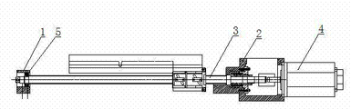
Fig. 1 is Digit Control Machine Tool ball screw drives structure schematic diagram of the present invention.
Fig. 2 is transmission case structural representation of the present invention.
Fig. 3 is ball screw structural representation of the present invention.
Fig. 4 is Digit Control Machine Tool ball screw drives structure partial enlarged drawing of the present invention.
The specific embodiment
As shown in Figure 1, comprise bearing block 1, transmission case 2, ball screw 3 and motor 4.
Above-mentioned bearing block 1 is fixed on lathe base one end, and transmission case 2 is fixed on the lathe base other end.
As shown in Figure 2, one side sidewall of transmission case 2 has the through hole that level connects transmission case 2 sidewalls, this through hole is stepped, its axis hole 21 and dead eye 22 by coaxial setting consists of, the internal diameter of axis hole 21 is less than dead eye 22 internal diameters, and dead eye 22 is positioned at the inboard of sidewall, and the transmission case inwall in the dead eye end bores some screwed holes 23 that distribute ringwise; The opposite side sidewall of transmission case has motor installing hole 24.
As shown in Figure 3, the left end of ball screw 3 arranges axle journal 31, opens jump-ring slot 32 on the axle journal, and right-hand member arranges inner ring limited step 33 and threaded portion 34, and the threaded portion is positioned at the right side of inner ring limited step.
The left end of ball screw 3 is bearing in the bearing block 1 by bearing group A, and bearing group A is deep groove ball bearing 5, and the end jump-ring slot of ball screw 3 is embedded with the axle bumper of being close to deep groove ball bearing inner ring outer face.
As shown in Figure 4, the right-hand member of ball screw 3 is bearing in the transmission case 2 by bearing group B, and bearing group B is made of the angular contact ball bearing 6 that is installed in the dead eye several.Angular contact ball bearing 6 is installed in the dead eye of transmission case 2, the cycle surface of outermost angular contact ball bearing props up the step surface of axis hole and dead eye formation, the inner ring end face of outermost angular contact ball bearing props up the inner ring limited step inboard of ball screw, and the inner ring limited step 33 of ball screw 3 is then spacing to the inner ring limited step outside by the projection of stretching out axis hole; Be fixed with trim ring 7 by screw on the madial wall of transmission case 2 jumping through rings shape distribution screwed holes, trim ring 7 props up the outer ring of medial angle contact ball bearing, the threaded portion of the ball screw inner ring locking nut 9 that is threaded, this inner ring locking nut 9 props up the inner ring of medial angle contact ball bearing by lasso 8.
Motor 4 is installed on the motor installing hole of transmission case 2, and motor 4 output shafts are connected with the right-hand member of ball screw 3 by shaft coupling 10.
Claims (1)
1. Digit Control Machine Tool ball screw drives structure, it is characterized in that: comprise bearing block, transmission case, ball screw and motor, bearing block is fixed on lathe base one end, and transmission case is fixed on the lathe base other end;
One side sidewall of transmission case has the through hole that level connects the transmission case sidewall, this through hole is stepped, its axis hole and dead eye by coaxial setting consists of, the internal diameter of axis hole is less than the dead eye internal diameter, and dead eye is positioned at the inboard of sidewall, and the transmission case inwall in the dead eye end bores some screwed holes that distribute ringwise; The opposite side sidewall of transmission case has the motor installing hole;
The left end of ball screw arranges axle journal, opens jump-ring slot on the axle journal, and right-hand member arranges inner ring limited step and threaded portion, and the threaded portion is positioned at the right side of inner ring limited step;
The left end of ball screw is bearing in the bearing block by bearing group A, and bearing group A is deep groove ball bearing, and the end jump-ring slot of ball screw is embedded with the axle bumper of being close to deep groove ball bearing inner ring outer face;
The right-hand member of ball screw is bearing in the transmission case by bearing group B, and bearing group B is made of the angular contact ball bearing that is installed in the dead eye several.Angular contact ball bearing is installed in the dead eye of transmission case, the cycle surface of outermost angular contact ball bearing props up the step surface of axis hole and dead eye formation, the inner ring end face of outermost angular contact ball bearing props up the inner ring limited step inboard of ball screw, and the inner ring limited step of ball screw is then spacing to the inner ring limited step outside by the projection of stretching out axis hole; Be fixed with trim ring by screw on the madial wall of transmission case jumping through rings shape distribution screwed hole, trim ring props up the outer ring of medial angle contact ball bearing, the threaded portion of the ball screw inner ring locking nut that is threaded, this inner ring locking nut props up the inner ring of medial angle contact ball bearing by the lasso that passes the trim ring center;
Motor is installed on the motor installing hole of transmission case, and motor output shaft is connected with the right-hand member of ball screw by shaft coupling.
Priority Applications (1)
| Application Number | Priority Date | Filing Date | Title |
|---|---|---|---|
| CN2012103771632A CN102862085A (en) | 2012-10-08 | 2012-10-08 | Ball screw driving structure for numerically-controlled machine tool |
Applications Claiming Priority (1)
| Application Number | Priority Date | Filing Date | Title |
|---|---|---|---|
| CN2012103771632A CN102862085A (en) | 2012-10-08 | 2012-10-08 | Ball screw driving structure for numerically-controlled machine tool |
Publications (1)
| Publication Number | Publication Date |
|---|---|
| CN102862085A true CN102862085A (en) | 2013-01-09 |
Family
ID=47441355
Family Applications (1)
| Application Number | Title | Priority Date | Filing Date |
|---|---|---|---|
| CN2012103771632A Pending CN102862085A (en) | 2012-10-08 | 2012-10-08 | Ball screw driving structure for numerically-controlled machine tool |
Country Status (1)
| Country | Link |
|---|---|
| CN (1) | CN102862085A (en) |
Cited By (5)
| Publication number | Priority date | Publication date | Assignee | Title |
|---|---|---|---|---|
| CN103639817A (en) * | 2013-11-19 | 2014-03-19 | 无锡京华重工装备制造有限公司 | Ball screw positioning structure |
| CN103722434A (en) * | 2013-11-26 | 2014-04-16 | 无锡京华重工装备制造有限公司 | Installing and positioning structure for ball screw transmission |
| CN107378536A (en) * | 2017-08-07 | 2017-11-24 | 江苏思维福特机械科技股份有限公司 | A kind of lathe precision drive seat |
| CN109027163A (en) * | 2018-10-16 | 2018-12-18 | 广东隆禾机械实业有限公司 | A kind of convenient accurately screw rod mounting structure |
| CN110645842A (en) * | 2018-06-26 | 2020-01-03 | 北京自动化控制设备研究所 | Electric steering engine in flat space |
Citations (6)
| Publication number | Priority date | Publication date | Assignee | Title |
|---|---|---|---|---|
| JPH01159152A (en) * | 1987-12-14 | 1989-06-22 | Toyoda Mach Works Ltd | Table driving device |
| US5140863A (en) * | 1989-12-25 | 1992-08-25 | Toyoda Koki Kabushiki Kaisha | Screw-nut feed mechanism |
| JPH0681926A (en) * | 1992-09-07 | 1994-03-22 | Hitachi Seiko Ltd | Supporting structure of feed screw |
| JPH1159152A (en) * | 1997-08-27 | 1999-03-02 | Nissan Motor Co Ltd | Rear suspension structure |
| CN1214289A (en) * | 1997-10-14 | 1999-04-21 | 北村机械株式会社 | Drive device for feed member in machine tool |
| CN201055955Y (en) * | 2006-09-20 | 2008-05-07 | 南通西马特机器制造有限公司 | Long stroke numerically controlled drilling machine feed gear of drill miller |
-
2012
- 2012-10-08 CN CN2012103771632A patent/CN102862085A/en active Pending
Patent Citations (6)
| Publication number | Priority date | Publication date | Assignee | Title |
|---|---|---|---|---|
| JPH01159152A (en) * | 1987-12-14 | 1989-06-22 | Toyoda Mach Works Ltd | Table driving device |
| US5140863A (en) * | 1989-12-25 | 1992-08-25 | Toyoda Koki Kabushiki Kaisha | Screw-nut feed mechanism |
| JPH0681926A (en) * | 1992-09-07 | 1994-03-22 | Hitachi Seiko Ltd | Supporting structure of feed screw |
| JPH1159152A (en) * | 1997-08-27 | 1999-03-02 | Nissan Motor Co Ltd | Rear suspension structure |
| CN1214289A (en) * | 1997-10-14 | 1999-04-21 | 北村机械株式会社 | Drive device for feed member in machine tool |
| CN201055955Y (en) * | 2006-09-20 | 2008-05-07 | 南通西马特机器制造有限公司 | Long stroke numerically controlled drilling machine feed gear of drill miller |
Cited By (5)
| Publication number | Priority date | Publication date | Assignee | Title |
|---|---|---|---|---|
| CN103639817A (en) * | 2013-11-19 | 2014-03-19 | 无锡京华重工装备制造有限公司 | Ball screw positioning structure |
| CN103722434A (en) * | 2013-11-26 | 2014-04-16 | 无锡京华重工装备制造有限公司 | Installing and positioning structure for ball screw transmission |
| CN107378536A (en) * | 2017-08-07 | 2017-11-24 | 江苏思维福特机械科技股份有限公司 | A kind of lathe precision drive seat |
| CN110645842A (en) * | 2018-06-26 | 2020-01-03 | 北京自动化控制设备研究所 | Electric steering engine in flat space |
| CN109027163A (en) * | 2018-10-16 | 2018-12-18 | 广东隆禾机械实业有限公司 | A kind of convenient accurately screw rod mounting structure |
Similar Documents
| Publication | Publication Date | Title |
|---|---|---|
| CN101628343B (en) | Boring and rolling combined processing tool | |
| CN102862085A (en) | Ball screw driving structure for numerically-controlled machine tool | |
| CN103158025B (en) | A kind of bearing integral supporting structure for ball-screw support end | |
| CN103433705B (en) | The processing technology of robot RV reducer pin wheel housing | |
| CN103143971A (en) | Pre-drawing structure of ball screw | |
| CN106363194B (en) | A kind of processing method of stator and equipment and rotor processing method and equipment | |
| CN102528557B (en) | Error compensation device of boring arbor | |
| CN204584940U (en) | The grinding equipment of boring lathe machining large inner bore of part | |
| CN102672535A (en) | Boring cutter rod error compensating device with slide block structure | |
| CN203115055U (en) | Speed changing box and bearing pre-tightening force adjusting device thereof | |
| CN203197647U (en) | Ball screw prestretching structure | |
| CN101633120A (en) | Double-division auxiliary static-pressure bearing and turning worktable of machine tool | |
| CN204603915U (en) | Ball screw integral bearing mechanism | |
| CN109158672B (en) | Sliding bearing oil groove machining device and milling machine and method for installing sliding bearing oil groove machining device | |
| CN104589126A (en) | Integral bearing mechanism for ball screw | |
| CN204018747U (en) | A kind of thin slice frock reducing clamping deflection | |
| CN104190962B (en) | A kind of plate holder reducing clamping deflection | |
| CN203751834U (en) | Multifunctional machine tool | |
| CN203664844U (en) | Steel ball type floating gear shaving clamp | |
| CN203176288U (en) | Support structure for support end of ball screw | |
| CN204585047U (en) | A kind of auxiliary mould structure of electro spindle assembling | |
| CN204094529U (en) | A kind of fixture being beneficial to thin slice object turnery processing end face flatness | |
| CN103465036A (en) | Ram component on processing machine tool | |
| CN202428303U (en) | Clamping device for bearing processing | |
| CN103358163A (en) | High-precision numerical control machine tool |
Legal Events
| Date | Code | Title | Description |
|---|---|---|---|
| C06 | Publication | ||
| PB01 | Publication | ||
| C10 | Entry into substantive examination | ||
| SE01 | Entry into force of request for substantive examination | ||
| C12 | Rejection of a patent application after its publication | ||
| RJ01 | Rejection of invention patent application after publication |
Application publication date: 20130109 |