CN1028467C - Adaptive video signal noise reduction system - Google Patents
Adaptive video signal noise reduction system Download PDFInfo
- Publication number
- CN1028467C CN1028467C CN90107012A CN90107012A CN1028467C CN 1028467 C CN1028467 C CN 1028467C CN 90107012 A CN90107012 A CN 90107012A CN 90107012 A CN90107012 A CN 90107012A CN 1028467 C CN1028467 C CN 1028467C
- Authority
- CN
- China
- Prior art keywords
- signal
- compandor
- companding
- output
- coupled
- Prior art date
- Legal status (The legal status is an assumption and is not a legal conclusion. Google has not performed a legal analysis and makes no representation as to the accuracy of the status listed.)
- Expired - Fee Related
Links
Images


Classifications
-
- H—ELECTRICITY
- H04—ELECTRIC COMMUNICATION TECHNIQUE
- H04N—PICTORIAL COMMUNICATION, e.g. TELEVISION
- H04N5/00—Details of television systems
- H04N5/14—Picture signal circuitry for video frequency region
- H04N5/21—Circuitry for suppressing or minimising disturbance, e.g. moiré or halo
Abstract
A video signal transmission system includes adaptive compansion circuitry to improve the signal-to-noise ratio of transmitted signals. A compandor (510) at the transmitter, and corresponding inverse compandor (600) at the receiver, are arranged to have a plurality of selectable compansion transfer characteristics. Selection (530, 600) of particular ones of the transfer characteristics is responsive to, e.g., predicted values (550, 570, 630, 640) of current signal.
Description
The present invention relates to use the video signal noise reduction system of compression expansion and prediction signal processing.
Generally to consider the degradation that how to prevent that interchannel noise from making the noise of vision signal when reset image having on the potential noisy communication channel to send such as the such vision signal of TV signal.Companding is to improve a kind of approach that transmits video signal quality under noise circumstance.Use companding technology, thereby the amplitude of compressed video signal improves its homogeneous peak power ratio in transmitter, and therefore improve anti-interference noise.This signal amplitude of carrying out is expanded with the inverse transfer function of transmitter compression function by receiver, thereby obtained correct shows signal to recover the original video signal amplitude distribution.If transmitter carries out non-linear compression, can be revised this signal by means of the combination of small-signal expansion and large-signal compression.In receiver, carry out complementary function.
Function noise power as compandor transfer function slope descends.Steeper slopes, noise reduction are many more.Interval with compandor transfer function of steep slope is subject to the consideration of dynamic range.Concerning most of signals, the dynamic range of signal is different in the different time interval range.If know the relative dynamic scope in different time interval in advance, just adjustable whole compandor transfer function is so that at each section operation optimum.Yet it should be noted that this relative dynamic range information must be effective to transmission in the companding system and receiving terminal both.
As everyone knows, from the vision signal high redundancy of horizontal line-horizontal line or frame-frame.Since this redundancy, the range value of the vision signal that can quite calculate to a nicety.The relative amplitude of known current video signal by according to occurring the prediction that signal carries out earlier, can be formulated the instantaneous dynamic range of the signal in each sigtnal interval.Use the predicted value of the vision signal that occurs continuously, can in video signal transmission system, realize self adaptation companding system.
The nonlinear amplitude compression of receiver can produce unwanted frequency band high frequency component signal in addition, for example, is higher than the frequency component of 4.2MHz under the situation of TV type vision signal.Can be by these unwanted high fdrequency components of output low pass filter cancellation of transmitter.But, might influence the precision of the complementary spread function of receiver in transmitting terminal cancellation frequency component.
Nominal noise in the representation image is not so good as so horrible in still image in containing the image of object of which movement.In addition, to the vision signal that transmitter was temporarily handled, non-linear companding is handled active images is produced than the frequency component beyond the more frequency band of still image.Therefore, come the benefit of companding vision signal to be the temporary transient still image of handling is carried out big companding and the temporary transient active images of handling are carried out less companding according to the active level of each image of resetting with different companding functions.
Implement the present invention in comprising the video signal transmission system of compandor, described compandor has the companding characteristic that plurality of optional is selected.Comprise a circuit, be used for the amplitude of for example vision signal is predicted, and determine to prepare the specific companding characteristic of use according to this result.
Fig. 1 and Fig. 2 can be respectively be used for the block diagram of companding device of companding vision signal at the end that transmits and receives of television system.
Fig. 3 and Fig. 4 are the block diagrams that the compressor-expander that transmits and receives part in the widescreen television signal processing system is shown respectively.
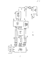
Fig. 5 A and 6 is respectively the block diagram that transmits and receives part self adaptation compressor-expander in the television signal transmission system.
Fig. 5 B is the circuit block diagram that is used to realize the compandor control unit of direct compandor and Fig. 5 A.
Fig. 7 and Fig. 8 are respectively the block diagrams of the optional embodiment of the self adaptation compressor-expander of radiating portion and receiving unit in the television signal transmission system.
Fig. 9 and Figure 10 are respectively the block diagrams that comprises the optional adaptive video signal companding of another of compressor-expander system that transmits and receives end of system.
Figure 11 illustrates the multiple compandor transmission characteristic that available self adaptation compandor is realized.
In the transmitter circuitry of Fig. 1, incoming video signal is added to an input of signal subtraction device 10, another input of this subtracter receives will be discussed from signal estimation network 15(back) signal.Carry out the nonlinear amplitude compression from the difference signal (DIFF) of vision signal subtracter 10 output, that expression was temporarily handled by the amplitude compression device 12 of the nonlinear transfer function shown in having on the square frame 12.12 pairs of large-signals greater than given amplitude threshold values of compressor reducer are carried out amplitude compression, and small amplitude signal is carried out amplitude expansion (amplification).The amplitude compandor that has complementary transfer function in compressor reducer 12 and the receiver constitutes an assembly in the companding system together.
The non-linear transmission characteristic of compressor reducer 12 can produce the unwanted high fdrequency component (for example, harmonic wave) that surpasses vision signal frequency range upper limit 4.2MHz in this example.In OUTPUT(output) before signal launches by the channel that may comprise the signal degradation noise, carry out filtering by the outer high fdrequency component of 14 pairs of above-mentioned frequency ranges of low pass filter.But filter 14 may cause the unwanted signal distortion of own institute.This filter distortion, and compression in actual that can occur and the transmitter and the inharmonious relevant distortion between the expansion especially under the movable situation of for example image, can be reduced under prediction network 15 cooperates and be eliminated.
Being used in fallout predictor 15 and amplitude expander and the receiver receives the predicted grid striking resemblances of the signal of Fig. 1 equipment emission.With reference to figure 2, transmitter has been made the signal that is received after the nonlinear amplitude compression, expand by the inverse function of amplitude expander 216 usefulness the transmitter nonlinear transfer functions amplitude of carrying out.Expander 216 as the compressor reducer in the transmitter 12, provides instantaneous transfer function, and available ROM form of look realizes.
Other element of Fig. 2 circuit is carried out and is comprised the good several functions of generation corresponding to the prediction signal of the prediction signal of Fig. 1 fallout predictor 15 generations.In Fig. 2, the output signal of expander 216 is video differential signals.Adder 218, delay element 220 and amplifier 222 are arranged in the closed-loop path, to form the leaky integrating device of video differential signal integration and the vision signal of reconstruct is provided at the output of adder 218.Delay element 220 can be a frame delay, and produces the predicted value of current video signal at its output because of the high redundancy characteristic of vision signal.The output of delay element 220 by in the amplifier 222 less than 1 factor weighting.Amplifier 220 provides basically the identical weight estimation signal of prediction signal that produces with fallout predictor 15.
The integrator that originally comprises element 218,220 and 222 forms recursion filter.Because the redundancy and the correlation properties of the vision signal of successive frame, the recursive filtering effect of integrator might improve the signal to noise ratio that adder 218 provides signal.
The forecasting process of example of the present invention relates to the sample value of crossing from the temporary delay of single figure image point, yet, think that it can comprise a plurality of sample values from a plurality of space correlation figure image point.Nominally be restricted to less than the numerical value of unit 1 scale factor " A " stable to keep the integrating network.
Get back to Fig. 1, the prediction signal of fallout predictor 15 outputs is represented to the receiver output signal that postpones, by the assessed value behind the factors A ratio scaling.Parts 10 deduct prediction signal, produce the difference signal of being handled by parts 12,13 from input signal, parts 12 and 14 produce output signals transmitted.
In the transmitter of Fig. 1, difference signal is poor between input signal and the prediction signal.Adder 18 former outputs are simulations of the output of receiver.Can see that the class signal of receiver output is similar to the signal that is added to the transmitter input.If the difference signal that subtracter 10 produces in the transmitter is little, (showing it is correct prediction), then amplifies this difference signal and before transmission, advantageously improve its signal-to-noise characteristic thus by nonlinear amplitude compressor reducer 12.
Disclosed system is run on the 4.2MHz luminance signal, can notice at scale factor A to be 0.75 and to adopt and to have μ when being the μ rule compandor of 11 companding parameter, noise abatement 2.7dB.At A=0.90 and μ is 40, but noise abatement 4.1dB.
Fig. 3 illustrates the block diagram of the encoder of compatible wide-screen television system (for example in order to handle the ratio of width to height signal of 5: 3), comprises that Fig. 1 illustrates the compression and the prediction network of type.Except this network, Fig. 3 system is disclosed in 4,816, No. 899 United States Patent (USP)s of people such as Strolle in more detail.
Among Fig. 3, the source 310 of widescreen television signal provides panavision chromatic image component Y(brightness with digital form) and I, Q(aberration).Source 310 also illustrates and includes matrix, A/D converter and low-pass filter circuit.Signal from source 310 is handled to produce three groups of output signal: YE, IE and QE by avris one central picture signal separator and processor 318; YO, IO and QO; And YH, IH and QH.Preceding two groups of signals (YE, IE, QE and YO, IO, QO) are handled to produce respectively comprised central picture component, time compression signal in the avris picture low-frequency brightness information (brightness low frequency component) in level image overscanning district.Handle the 3rd group of signal (YH, IH, QH) comprises avris picture high-frequency information (avris picture high fdrequency component) with generation signal.Made up as the central authorities and the signal component of avris picture the most at last, just produce the wide screen signaling of NTSC compatibility with 4: 3 demonstration the ratio of width to height.Except avris picture high-frequency information, signal YO, IO and QO provide the low frequency avris image information that inserts a left side and right horizontal overscan district.Signal YO, IO and QO are by avris one central signal synthesizer 328(time multiplexer for example) with signal YE, IE and QE combination before, individually handle by (type shown in Figure 1) amplitude compression in the piece 322 and prediction network.Synthesizer 328 produces signal YN, IN and the QN with 4: 3 image aspects of standard.
Signal processor and NTSC encoder 336 processing signals YN, IN and QN are to produce the synthesized output signal C/SL of NTSC compatibility, and this signal comprises central image information and is compressed to the avris picture low frequency signal in horizontal overscan district.Parts 336 comprise brightness and chrominance filter, dispersive modulator and are used to encode the conventional NTSC coding circuit of brightness and chrominance information.
Avris picture high fdrequency component YH, IH and QH make additional treatments by parts 343 after by parts 321 temporal extension.In parts 343, avris picture high fdrequency component is with the auxiliary compression of the anti-phase modulation of field frequency subcarrier.Subcarrier after the modulation forms avris picture high frequency signal SH through amplitude compression and bandpass filtering.This signal produces the signal NTSC of wide screen compatibility with signal C/SL combination in synthesizer 340.Signal NTSC is transformed to analog form being added to radio frequency modulator and reflector network 355 with by before antenna 356 broadcast transmission by D/A (DAC) 354.
Amplitude compression and prediction network 322 can adopt the enhancing picture resolution pattern in the wide screen coded system of people's such as Strolle the disclosed explanation of patent similarly.This enhancing resolution system is disclosed in exercise question in No. 139,339, the United States Patent (USP) of the common submission of " compatible TV system that comprises auxiliary signal coded message companding ".
Fig. 4 has described to be used for the block diagram of wide-screen receiver decoder of the widescreen television signal of the compatibility that Fig. 3 transmitter coding device produces.Except expansion and prediction network 422, the system of Fig. 4 is disclosed in people's such as aforementioned Strolle the patent in more detail.
The compatible widescreen signal of emission is received, is separated mediation Signal Processing Element 422 demodulation and produced signal YN, IN, QN and avris picture high frequency signal SH by input by antenna 410.Parts 422 comprise filtering and amplitude extended network that is used for restoring signal SH and filtering and the look demodulation network that is used for restoring signal YN, IN and QN.Processor 454 response avris high frequency signal SH are to produce signal YH, IH and QH.In processor 454, to the intermediate subcarrier demodulation, brightness is separated with colourity avris picture high fdrequency component, with brightness avris high fdrequency component time compression, thus signal component YH, IH and the QH of generation avris picture high fdrequency component.
By means of avris one central separator (demultiplexer) 440 signal YN, IN and QN are separated into low frequency avris picture component YO, IO, QO and central picture component YE, IE and QE.Carry out time compression to occupy the central picture-display-region of regulation by parts 444 couples of signal YE, IE, QE.Signal YO, IO, QO by parts 445 temporal extension with the avris picture-display-region that occupies regulation before, in network 442, individually carry out amplitude expansion and prediction signal processing.Network 442 comprises the circuit that is used for difference processing signals YO, IO and QO of type shown in Figure 2.
In parts 446,, produce avris picture brightness and carrier chrominance signal YS, IS, QS to making up from the avris picture low frequency component signal of time spreading device 445 and the avris picture high frequency signal of from processor 454.By means of connector 460 the avris picture signal YS of reconstruct, IS, QS are engaged with central picture signal YC, IC, QC from the reconstruct of time compression device 444, form the wide screen signaling of the complete reconstruct that comprises component Y, I and Q.
Wide screen signaling Y, I, Q were transformed to analog form by D/A (DAC) 462 before being added to video signal preprocessor and matrix amplifier 464.The video signal preprocessor component of parts 464 comprises signal amplification, DC level shift, peak value, brilliance control, contrast control and other video processing circuit of universal performance.Matrix amplifier 464 is represented brightness signal Y and color difference signal I and Q combination with the generation chromatic image vision signal R, G and B.By the display driver amplifier in the parts 464 these chrominance signals are amplified to and are suitable for directly driving wide screen color image diplay 470, for example level of wide screen picture tube.
As mentioned above, the encoder circuit of Fig. 3 is encoded to low frequency avris image information with the time compression form.Intuitively, the monochrome information from the direct current to 700KHz is approximately 6: 1 time compression so that this avris picture low frequency information occupies the 4.2MHz bandwidth.Receiver (Fig. 4) is carried out described corresponding temporal extension.Nonlinear amplitude compression process in the transmitter might produce the frequency outside the unwanted frequency band especially, and in this example, the time compression process produces that frequency equals or near the signal of the upper limiting frequency of desired frequency band (for example 4.2MHz).
Because time compression and expansion, avris low frequency component contained noise energy under the noisy communication channel condition is more much bigger than the same frequency range noise energy of central image information.This situation itself has been expressed the tedious difference between the image of shown central picture and avris picture.Specifically, the band noise of the broad of avris picture image and central picture image is compared the low-frequency noise that presents level " inhomogeneous ", and is therefore more disagreeable.So visible avris image information is different from central image information, is like this to the transmission channel with the following signal to noise ratio of about 35db especially.Like this, preferentially use the equipment of Fig. 1 and Fig. 2 to strengthen the noise characteristic of the avris picture low frequency information of time compression.Disclosed equipment alternately is used in the transmitter system of Fig. 3 between parts 318 and the time compression device 320, and in this case, the output signal path of Fig. 1 equipment can low-pass filtering to 700.KHz is to carry out compression in 6: 1 to the brightness low frequency component.
Disclosed signal companding and predict device also can be used for avris picture high-frequency signal YH, IH and QH from the temporal extension of Fig. 3 parts 321 are handled.It should be noted that in this respect and utilize system shown in Figure 3 that because the temporal extension of expander 321, avris picture high-frequency information signal to noise ratio can obtain improvement.Yet the amplitude fading that this improvement is subjected to the intermediate subcarrier of 343 pairs of avris high fdrequency component modulation of parts damages, and makes that the intermediate subcarrier of modulation is not obvious when the standard TV receiver with 4: 3 the ratio of width to height of standard receives widescreen television signal.Disclosed noise reducing apparatus can be used for strengthening according to the needs of concrete system the noise anti-interference of avris high-frequency component information.
Again with reference to figure 1, the professional of video system design is understandable that the amplitude of the difference signal that is provided by subtracter 10 is a function movable in the frame.The consideration ratio because of A be set to 1.In this case, if consecutive image is all similar, promptly represent still image, this difference signal amplitude is 0.On the contrary, as the consecutive image difference, then this difference signal is represented the difference between consecutive image, and is by a relatively large margin.The energy density of difference signal increases with the increase of consecutive image differences.
By the accessible noise reduction degree of the companding function that is input signal statistic and output signal channel dynamic range.If at interval the dynamic range of the input signal of compandor is known to concrete signal, is useful for corresponding dynamic range finishing companding function selectively.
With reference to Fig. 5 A that illustrates from adaptive video signal companding system, this system transter can be selected according to the picture motion situation.Incoming video signal is added to an input of subtracter 500, and will be added to second input of subtracter 500 by the vision signal of element 580 and 570 ratio scalings and frame delay.To still image and (or) static image region, the dynamic range and the amplitude of the difference that is provided by subtracter 500 are quite little.To the image of active images and its brightness variation, the dynamic range of this difference and amplitude increase.
To be added to from the difference of subtracter 500 and have the compandor circuit 510 that to select transfer function, this transfer function to the predetermined amplitude range of input signal (for example, be about 0) have slope greater than 1, and to the input signal amplitude beyond preset range, its slope is less than 1.Output signal from compandor 510 sends to the receiving equipment (not shown).Output signal from compandor 510 also is coupled to the contrafunctional compandor 520 of carrying out compandor 510.Compandor 520 emulation place the compandor of receiving equipment.To be coupled to from the expansion difference of compandor 520 on the circuit that comprises adder 560, delay cell 570 and scaler 580, the difference signal of expanding will be carried out integration to produce the calibration prediction of input signal.In this embodiment, the total delay in the loop between the output and second input is a visual cycle, for example, and horizontal line interval, interval, a field or a frame period etc.The signal delay that selection is provided by delay element 570 is to satisfy this restriction.From the viewpoint of this restriction, be necessary the compensating delay element is included on certain signal path, for example between the element 580 and 560.Yet the people who is familiar with circuit design is readily appreciated that these requirements and adds necessary element.
Move and to be detected by deducting vision signal between periodic signal variation or image between image from the consecutive image cycle.This can be in subtracter 550 deducts the current video sample value that is added to delay element 570 by the vision signal of a visual cycle output of delay of self-dalay element 570 always and realizes.To be added to by the motor message that subtracter 550 provides low pass filter 540 with the influence of revising noise in the vision signal or quantization error and (or) variation of prevention abrupt motion signal.Motor message behind the paper pass filter is coupled to the compandor control circuit 530 of the transmission characteristic of determining compandor 510 and 520.
Compandor control circuit 530 in the digital signal processing appts and compandor circuit 510(520) can realize with circuit unit 531 and 511 respectively, shown in Fig. 5 B.Compandor control circuit 531 is read-only memory (ROM), will be added to the address input end mouth of this ROM from the motor message of low pass filter 540.Each memory cell at ROM 531 weaves program in advance with output and the corresponding correct control signal of each address value.For example, can programme to ROM 531, the address value of 0-20 unit is provided the control signal of binary value 00, the address value of 21-40 unit is provided the control signal of binary value 01, address value to 41-60 unit provides 10 binary system controlling value, and provide 11 binary system controlling value to address value greater than 60 units, etc.
Compandor 511 is another ROM, and vision signal is coupled to some address input ends of this ROM and control signal is coupled to its other address input ends.The memory cell of ROM 511 is arranged in a plurality of tables, with specific companding function each table is programmed.Employed specific table depends on the value of control signal.Video difference signal is to the respective memory unit addressing in the used table, is programmed with the companding output signal corresponding to each address value in these unit.For example, ROM 511 can comprise by control address 00,01,10 and 11 4 tables selecting.Suppose that those control address are corresponding to the controlling value in giving an example for ROM 531.In this case, can be predefined for companding input signal by defined companding function in the table of continuous big controlling value addressing with continuous optimum by a relatively large margin.
Fig. 6 illustrates the receiving unit of this self adaptation companding system.In Fig. 6, the video difference signal of the companding that sends is coupled to is similar to the passing of Fig. 5 A compandor 520 to compandor 600.The video difference signal of the expansion that will be provided by reverse compandor 600 is added to the circuit unit that comprises adder 610, delay element 630 and scaler 620, so as to the video difference signal integration to reappear raw video signal.Be similar to motion detection circuit among Fig. 5 A, motion detection circuit comprises subtracter 640 and the low pass filter 650 that is coupled to delay cell 630, is coupled to the motor message of compandor control circuit 660 in order to generation.Motor message is responded, and this compandor control circuit 660 is controlled the transmission characteristic of compandor 600 adaptively.
Compandor 510 in the emission system produces the strong signal that is not subjected to the appreciable impact of transmission channel noise.Therefore, the signal that is added to compandor 600 in the receiver is substantially similar to and is added to the signal on the compandor 520 in the transmitter.Because the circuit of Fig. 6 is similar to the combination of the circuit element 520-580 of Fig. 5 A, so accurately its response of emulation.Again, process errors is for minimum because the circuit arrangement of Fig. 5 A becomes closed feedback loop, and therefore, the output of the output of adder 560 and adder 610 is accurate expressions of original input signal.
Fig. 7 is the optional embodiment of self adaptation companding system.Fig. 7 equipment class is similar to Fig. 5 A equipment and moves like that, except the generation of compandor control signal.Among Fig. 7, compandor 710 and 720 is provided by the desired dynamic range of the signal difference that is provided by subtracter 700, rather than is transferred to picture motion.
The value scope of supposing input signal is from 0 to 100 unit.The dynamic range of the difference that is provided by subtracter 700 is 200 units like this, i.e. from-100 to+100 units.But, if amplitude that could predicted input signal, just the dynamic range of so measurable difference signal.Suppose that the amplitude of predicted input signal is X, the amplitude range of difference signal is to 100-X unit from-X so.For example, as the prediction X be 25, real input signal is in 0 or 100 limit, so difference signal be-25 or+75, its dynamic range is 100 units.So according to the amplitude prediction to input signal values, the dynamic range of the signal that subtracter 700 can be provided reduces 1/2.But this is the dynamic range of floating, that is, and unfixing concrete amplitude limits.Yet, known the predicted value of input signal at any time, just know the limit of the dynamic range that this floats constantly, and select the transmission characteristic of compandor according to the relative position of the current dynamic range of signal difference.
The delay of Fig. 7 integrating network separates in element 770 and 750.Selecting these combination of elements to postpone to make the total delay in the loop between subtracter 700 outputs and input is a visual cycle.Separately postpone, so as to adjust prediction circuit make its response sequential correctly time unifying in the signal that is added on the compandor.
The space filtering that is undertaken by 740 pairs of a plurality of pixels of filter or on average realize the incoming signal level prediction, described a plurality of pixels are for example from former frame and be in corresponding near the current represented pixel of input signal.Prediction signal value from spatial filter 740 is coupled to compandor control circuit 730.The prediction signal that spatial filter 740 provides is carried out low-pass filtering, in case this process of noise jamming or prevent that perhaps the undue variation of companding function from meeting the requirements.
Each table with the transfer function of the unlike signal dynamic range that is suitable for being determined by control signal carries out pre-programmed to compandor ROM 511.
Fig. 8 illustrate be in receiving terminal, with the companding equipment of Fig. 7 companding system support.As seen from Figure 8, this circuit except the optional nucleation circuit 800 that will be explained below, comprise the signal estimation and the compandor control circuit that are similar to Fig. 7 equipment.With element among Fig. 8 of element numbers appointment among similar Fig. 7, carry out identity function.
Fig. 9 illustrates another optional embodiment of video signal self-adaptive compressor-expander.But this circuit on-line operation is in vision signal rather than vision signal difference.
General compandor (being positioned at system's transmitting terminal) moves the amplitude of expanding the low amplitude signal and the amplitude of compressing higher amplitude signal, to improve signal to noise ratio.This process may improve the quality than low level signal, but what improvement is higher level signal almost do not had.If the relative amplitude of known pending signal can improve the almost signal to noise ratio of any level signal by the self adaptation companding so on the other hand.This can finish by selecting its greatest gradient to be positioned at the companding transmission characteristic that signal sample amplitude interval appears in expectation.Consider the companding curve shown in Figure 11, the compandor that these curves are realized companding system transmitting terminal is suitable for.(be appreciated that by changing shaft orientation layout from input and output to output with input, curve can corresponding to companding curve contrary or receiving terminal).Can know, if the amplitude of wishing input signal is for example between 80 and 100 IRE, just can expand the signal of this scope, and the less signal of suppressed range.On the other hand, be 50 IRE as this signal of hope, then expand the signal of 50 ± 10 IRE scopes and compress more greatly or signal more by a small margin.We can say that Yun Hang system is an amplitude tracking companding system by this way.By chance, come voluntarily row, to the field, or frame allows to finish this tracking companding system to the high reciprocation of frame video signal.
Among Fig. 9, the vision signal for the treatment of companding is added to many characteristics compandor 900, this compandor 900 provides companding signal to be sent at end OUTPUT.Compandor 900 can be the ROM with the programming of the table of a plurality of transmission characteristics, each table definition one such as the described companding characteristic of Figure 11.Depend on the control signal that produces by compandor control circuit 980 in the used particular table of any given time.
The companding signal also is coupled on the contrary compressor-expander that comprises element 910-980 the expanded circuit of this circuit simulation transmission system receiving terminal.To be added to first signal estimation circuit that comprises element 920-923 and the secondary signal prediction circuit that comprises element 930-936 from the spread signal of compandor 910.
Second prediction circuit comprises the cascade circuit of delay element 930, delay element 931 and 932, delay element 930 deducts a horizontal line cycle with video frame period of signal delay, and in delay element 931 and 932 first is with horizontal line cycle of signal delay.In the future self-dalay element 930,931 and 932 vision signal are coupled to signal weighting circuit 935,934 and 933 respectively.935,934 and 933 pairs of institute's plus signals of weighting circuit multiply by the factor 1/4,1/2 and 1/4 respectively.From vision signal addition in add circuit 936 of weighting circuit 933-935, produce on the time and the prediction signal of current video signal correction.To be coupled to variable weighting circuit 942 from the time prediction signal of adder 936, the variable factor K that this variable weighting circuit 942 can be provided time prediction signal scaling by control-signals generator 960 doubly.
The time prediction signal can comprise the component from current image.This can be pointed out by the dotted arrow line of 936 of the output of compandor 910 and add circuits.The signal that this line is used to refer to one or more figure image points of current picture frame can be weighted and make up with signal from former frame.
First prediction circuit produces a prediction signal according to the signal from current image field.In the one exemplary embodiment of Fig. 9, will postpone the time that a horizontal line cycle deducts T from the output signal of compandor 910 by delay element 920.Time T normally equals the short cycle of 1/4 or its several times of color subcarrier cycle.This inhibit signal is further postponed by cascade delay element 921 and 922, and it is the delay of T that delay element 921 and 922 respectively provides the cycle.The inhibit signal of self-dalay element 920-922 is coupled in the calibration and combinational circuit 923 that produces the spatial prediction signal in the future.Calibration and combinational circuit 923 can be similar to the element 933-936 in the time prediction circuit.The spatial prediction signal that element 923 provides is coupled to variable solid son (1-K) the variable weighting circuit 940 doubly that spatial prediction signal scaling is provided by control circuit 960.
To inertia image or do not contain the image region of interframe movement, time average may be that current demand signal is predicted more accurately.To active images, or contain the image region of interframe movement, spatial mean value may be that current image is predicted comparatively accurately.When making system's operation well under the picture motion and the condition of not moving, the spread signal from compression compandor 910 is monitored its motion so that carry out selection to suitable prediction signal.
To be coupled to the add circuit 944 of generation from the weighted space and the time prediction signal of weighting circuit 940 and 942 corresponding to institute's requirement forecast signal sum.To be coupled to compandor control circuit 980 from the prediction signal of add circuit 944.Compandor control circuit 980 response produces suitable control signal from the prediction signal of add circuit 944 can select concrete a kind of operation the in the transmission characteristic to adjust compandor 900 and 910 by it.Notice compandor control circuit 980 and compandor 900(910) can be configured to be similar to the circuit shown in Fig. 5 B.
Figure 10 system receiving terminal is shown with the system transmitting terminal on the compressor-expander that combines of Fig. 9 compressor-expander.With with Fig. 9 equipment in the element pointed out of the same label of element be similar and carry out similar functions.
Turn back to Fig. 8 again, consider to comprise the recursive loop of element 750-780.This recursive loop might increase the noise power of adder 760 outputs, although signal to noise ratio has been improved in this loop.The increase of this noise power can reduce by nucleation circuit 800 is inserted between weighting circuit 780 and the adder 760.If this nucleation circuit is contained in Fig. 8 circuit, similar nucleation circuit also just is included in the output of Fig. 7 weighting circuit 780 so that the prediction signal that is produced by Fig. 7 and Fig. 8 equipment is similar.This nucleation circuit 800 also can be the custom circuit with the clamped transfer function to a predetermined value of signal that has in the particular range of amplitude, and the signal beyond this particular range is transmitted without change.For example, this nucleation circuit can be respectively by greater than with less than all signal amplitude values of IRE for example ± 5, and the signal amplitude between positive and negative 5 IRE is clamped to 0 IRE value.On the other hand, the nucleation circuit also can be from suitable adaptive form, for example, United States Patent (USP) 4,538, the nucleation circuit that proposes in No. 236 is here in conjunction with for referencial use.
Preferably perhaps be that the nucleation circuit is included in any equipment of Fig. 1, Fig. 2, Fig. 5 A and Fig. 6-Figure 10, and this nucleation circuit can be assemblied in the position beyond weighting circuit (for example 780) output.For example, in Fig. 7 and Fig. 8, the nucleation circuit can be placed between adder 760 and the delay element 750, or place between compandor 720 and the adder 760.In this case, effect is to reduce the noise power of adder 760 outputs.It also is favourable that the nucleation circuit is inserted between delay element 750 and the compandor control circuit 730.
Use the nucleation circuit also to help the lower quantization error.Example is to be inserted in the nucleation circuit 970 between the add circuit 944 and compandor control circuit 980 among Fig. 9 and Figure 10.Consider that the structure generator only produces corresponding to 0,1/8 ... 9 different K values of 7/8,1, and weighting circuit 940 and 942 is displacement and type of addition.In this case, the output of adder 944 can produce with quantization error and.This quantization error might be more remarkable to the low amplitude signal.So, be preferably in the possibility of eliminating error in the lowest range of prediction signal.Coring circuit 970 has and the signal amplitude preset range is about 0 the transfer function of 0 value output signal is provided, and transmits all other signals, thereby has eliminated the quantization error of low level signal.
Being appreciated that on certain signalling channel of each circuit of Fig. 5-Figure 10 to need the compensating delay element, so as correctly time unifying in prediction signal and (or) have a control signal of current input sample.Yet the technical staff of circuit design field readily appreciates that this delay is whether necessary and they is attached in its system.In addition, low pass filter can be inserted in Fig. 5 A, 7 or 9 circuit directly and between the negate compandor frequency component beyond the frequency band that produces by non-linear companding with cancellation.At last, be appreciated that and Fig. 5 A, 7 or 9 equipment can be attached to Fig. 3 wide screen video signal transmission system, and Fig. 6,8 or 10 equipment can be attached in corresponding Fig. 4 wide screen video signal receiving system.Although compressor-expander only is illustrated in the avris picture low frequency signal path of Fig. 3 and Fig. 4, the similar compressor-expander of type described herein also can be contained in the avris picture high-frequency signal path.
Claims (18)
1, a kind of adaptive video signal noise reduction system, this system has and has the compandor of controllably variable non-linear transmission characteristic in order to processing signals, it is characterized in that, be connected to the signal monitoring apparatus of the output signal of described compandor in order to the predetermined attribute of definite described vision signal, the output that is connected to described signal monitoring apparatus is in order to the signal generation device of generation control signal when described prearranged signal attribute occurs and in order to described control signal is coupled to the device that described compandor will reduce from the noise in the output signal of described compandor with the nonlinear characteristic that changes described compandor.
2, the system as claimed in claim 1 is characterized in that, this system is used for handling:
Represent the self adaptation companding signal of described vision signal, it comprises:
Has control end, and have response and be added in a plurality of described compandors (600) of selecting the companding transmission characteristic of described control end control signal, described compandor responds described self adaptation companding signal to carry out the companding function, produces the non-companding signal of the described vision signal of expression
Be coupled to the device (610) of the output of described self adaptation compandor with the generation outputting video signal,
Respond described outputting video signal and point out the device (630-650) of the signal of described vision signal attribute with generation,
Respond the described device (660) of signal of pointing out described vision signal attribute to produce described control signal.
3, system as claimed in claim 2 is characterized in that, the described device that is used to produce the signal of pointing out attribute comprises and is used to produce the motion detector (950) of pointing out the motor message that moves between image.
4, system as claimed in claim 3 is characterized in that, the described device that is used to produce the signal of pointing out attribute also comprises:
Respond described outputting video signal with the device (920-923) of generation by the spatial prediction of the described video amplitude of described self adaptation companding signal indication,
Respond described outputting video signal in order to the device (930-936) of generation by the time prediction of the described video amplitude of described self adaptation companding signal indication, and
Respond described motor message, described spatial prediction and described time prediction and point out the device (940-944,960) of the described signal of attribute in order to generation.
5, system as claimed in claim 4 is characterized in that, it comprises and is used for the described attribute signal of pointing out is coupled to the nucleation circuit (970) of the described device that is used to produce described control signal.
6, system as claimed in claim 2, it is characterized in that, described be used to produce the signalling of pointing out attribute comprise the described outputting video signal of response, in order to produce expression to device (740) by the signal of the spatial prediction of the described video amplitude of described self adaptation companding signal indication.
7, system as claimed in claim 6 is characterized in that, the described device that is used to produce the signal of pointing out attribute also comprises:
Respond described outputting video signal producing expression to device (930-936) by the signal of the time prediction of the described vision signal of described self adaptation companding signal indication, and
Be used to make up the described signal of representing described time and spatial prediction is pointed out the described signal of attribute with generation device (940-944,960).
8, system as claimed in claim 6 is characterized in that, it comprises: be used for will the described spatial prediction of expression described signal be coupled to the nucleation circuit (970) of the described device that is used to produce described control signal.
9, system as claimed in claim 2, it is characterized in that the described device (630-650) that is used to produce the signal of indication attribute comprises that the described outputting video signal of response is to produce the device (740) of expression by the signal of the prediction of the video amplitude of described self adaptation companding signal indication.
10, system as claimed in claim 9 is characterized in that, it also comprise be used for will expression prediction described signal be coupled to the nucleation circuit (970) of the described device that is used to produce described control signal.
11, system as claimed in claim 9 is characterized in that, it comprises the nucleation circuit (800) that described outputting video signal is coupled to the described device of the signal that is used to produce the expression prediction.
12, system as claimed in claim 2, it is characterized in that, the self adaptation companding signal of described expression vision signal is the difference signal of expression from the companding of the difference of the vision signal in consecutive image cycle, and is used to provide the described device of described outputting video signal to comprise:
Signal combination device (610), this device have the first input end that is coupled to described self adaptation compandor output, and second input and be used to provide the output of described outputting video signal,
Its input is coupled to the deferred mount (630) of described signal combination device output, and this deferred mount has an output, and described deferred mount is used for institute's plus signal delay is essentially the time in 1 visual cycle, and
Its input and output side is coupled to the weighting circuit (620) of described deferred mount output and described signal combination device second input respectively, in order to institute's plus signal be multiply by 1 or less than 1 the factor.
13, system as claimed in claim 12 is characterized in that, it also comprises the signal nucleation circuit that is coupled between described signal combination device output and the described deferred mount input.
14, system as claimed in claim 12 is characterized in that, it also comprises: be coupled in the nucleation circuit (800) between described deferred mount output and described signal combination device second input.
15, system as claimed in claim 12 is characterized in that, the described device that is used to apply the self adaptation companding signal of expression vision signal comprises:
The video signal input terminal of incoming video signal is provided,
Its first input end is coupled to described video signal input terminal, and has the subtraction signal composite set (700) of second input and output,
Another self adaptation compandor (720), its input is coupled to described subtraction signal composite set output, its output provides the described self adaptation companding signal of the described vision signal of expression, and has and is used to produce a control input end of described device (730) coupling of described control signal, described another self adaptation compandor responds described control signal, carry out and the anti-phase companding function of described self adaptation compandor, and
Be used for the output of described weighting circuit (780) is coupled to the device of described subtraction signal composite set second input.
16, system as claimed in claim 15 is characterized in that, it comprises the signal nucleation circuit that is coupled between described signal combination device output and the described deferred mount input.
17, system as claimed in claim 15 is characterized in that, it comprises the signal nucleation circuit (800) that is coupled between described deferred mount output and described signal combination device second input.
18, system as claimed in claim 2 is characterized in that, the described device that is used to apply the self adaptation companding signal of expression vision signal comprises:
The video signal input terminal of incoming video signal is provided,
Another self adaptation compandor (520), its input is coupled to described video signal input terminal, its output is used to provide the described self adaptation companding signal of expression vision signal, its control end is coupled to the described device (530) that is used to produce control signal, and the described control signal of described another self adaptation compandor (520) response is to carry out and the anti-phase companding function of described self adaptation compandor.
Applications Claiming Priority (2)
| Application Number | Priority Date | Filing Date | Title |
|---|---|---|---|
| US07/416,695 US5005082A (en) | 1989-10-03 | 1989-10-03 | Video signal compander adaptively responsive to predictions of the video signal processed |
| US416,695 | 1989-10-03 |
Publications (2)
| Publication Number | Publication Date |
|---|---|
| CN1050801A CN1050801A (en) | 1991-04-17 |
| CN1028467C true CN1028467C (en) | 1995-05-17 |
Family
ID=23650938
Family Applications (1)
| Application Number | Title | Priority Date | Filing Date |
|---|---|---|---|
| CN90107012A Expired - Fee Related CN1028467C (en) | 1989-10-03 | 1990-09-30 | Adaptive video signal noise reduction system |
Country Status (13)
| Country | Link |
|---|---|
| US (1) | US5005082A (en) |
| EP (1) | EP0494945B1 (en) |
| JP (1) | JP2989005B2 (en) |
| KR (1) | KR100230860B1 (en) |
| CN (1) | CN1028467C (en) |
| AU (1) | AU6540290A (en) |
| CA (1) | CA2067246C (en) |
| DE (1) | DE69016211T2 (en) |
| ES (1) | ES2067045T3 (en) |
| MY (1) | MY107138A (en) |
| PT (1) | PT95500B (en) |
| TR (1) | TR24920A (en) |
| WO (1) | WO1991005435A1 (en) |
Families Citing this family (21)
| Publication number | Priority date | Publication date | Assignee | Title |
|---|---|---|---|---|
| US5122868A (en) * | 1990-10-18 | 1992-06-16 | General Electric Company | Side panel signal processor for a widescreen television system |
| US5155580A (en) * | 1991-01-07 | 1992-10-13 | General Electric Company | Side panel signal processor for a widescreen television system |
| GB9107144D0 (en) * | 1991-04-05 | 1991-05-22 | Rank Cintel Ltd | Recording video signals on cinematographic film |
| JPH04373277A (en) * | 1991-06-21 | 1992-12-25 | Sony Corp | Smear correcting circuit |
| JPH0591341A (en) * | 1991-09-26 | 1993-04-09 | Fuji Xerox Co Ltd | Picture data processing device |
| US5905533A (en) * | 1992-05-20 | 1999-05-18 | Nikon Corporation | Image processing apparatus |
| US5432557A (en) * | 1992-09-07 | 1995-07-11 | U.S. Philips Corporation | Extended television signal receiver |
| WO1994006247A1 (en) * | 1992-09-08 | 1994-03-17 | Paul Howard Mayeaux | Machine vision camera and video preprocessing system |
| US5357278A (en) * | 1993-01-14 | 1994-10-18 | Sony Electronics, Inc. | Integrated linear/non-linear static and controllable dynamic companding |
| TW297202B (en) * | 1993-10-13 | 1997-02-01 | Rca Thomson Licensing Corp | |
| US6285710B1 (en) * | 1993-10-13 | 2001-09-04 | Thomson Licensing S.A. | Noise estimation and reduction apparatus for video signal processing |
| US6122016A (en) * | 1994-11-14 | 2000-09-19 | U.S. Philips Corporation | Video signal processing |
| JP4028900B2 (en) * | 1996-01-11 | 2007-12-26 | 富士通株式会社 | Moving picture coding apparatus and moving picture decoding apparatus |
| EP1059811A2 (en) * | 1999-06-10 | 2000-12-13 | Fuji Photo Film Co., Ltd. | Method and system for image processing, and recording medium |
| US6384905B1 (en) | 2000-07-07 | 2002-05-07 | The United States Of America As Represented By The Secretary Of The Navy | Optic flow sensor with fused elementary motion detector outputs |
| US7225135B2 (en) * | 2002-04-05 | 2007-05-29 | Lectrosonics, Inc. | Signal-predictive audio transmission system |
| US6822595B1 (en) * | 2003-06-18 | 2004-11-23 | Northrop Grumman Corporation | Extended range digital-to-analog conversion |
| EP1658727A1 (en) * | 2003-08-22 | 2006-05-24 | Koninklijke Philips Electronics N.V. | Joint spatial-temporal-orientation-scale prediction and coding of motion vectors for rate-distortion-complexity optimized video coding |
| EP1919209A1 (en) * | 2006-10-31 | 2008-05-07 | Sony Deutschland Gmbh | Method and device for fast and effective noise reduction |
| TWI358220B (en) * | 2008-04-21 | 2012-02-11 | Ra Link Technology Corp | Signal transmitting apparatus for ofdm system and |
| US11558078B1 (en) * | 2021-08-17 | 2023-01-17 | Analog Devices International Unlimited Company | Lookup table (LUT) interpolation with optimized multiplier width using companding in correction slope |
Family Cites Families (10)
| Publication number | Priority date | Publication date | Assignee | Title |
|---|---|---|---|---|
| NL190093C (en) * | 1979-12-17 | 1993-10-18 | Victor Company Of Japan | COMPRESSING AND EXPANDING SYSTEM. |
| US4516167A (en) * | 1982-11-30 | 1985-05-07 | Rca Corporation | Compression of the dynamic range of video signals |
| US4518994A (en) * | 1982-12-20 | 1985-05-21 | Rca Corporation | Communication system compandor |
| US4520396A (en) * | 1983-07-25 | 1985-05-28 | Rca Corporation | FM video transmission system having coring and coring compensation for reducing effects of triangular noise |
| US4575749A (en) * | 1983-07-28 | 1986-03-11 | Rca Corporation | Component companding in a multiplexed component system |
| JP2601810B2 (en) * | 1986-12-22 | 1997-04-16 | 株式会社東芝 | Noise reduction circuit |
| GB8701475D0 (en) * | 1987-01-23 | 1987-02-25 | British Broadcasting Corp | Predictive techniques to analogue transmission of video signals |
| JP2579930B2 (en) * | 1987-03-17 | 1997-02-12 | 株式会社東芝 | Composite signal separation circuit |
| GB2203012B (en) * | 1987-03-30 | 1991-02-20 | Sony Corp | Differential pulse code modulation |
| JPS6464481A (en) * | 1987-09-04 | 1989-03-10 | Japan Broadcasting Corp | Emphasis/deemphasis circuit |
-
1989
- 1989-10-03 US US07/416,695 patent/US5005082A/en not_active Expired - Lifetime
-
1990
- 1990-09-11 MY MYPI90001561A patent/MY107138A/en unknown
- 1990-09-18 JP JP2514332A patent/JP2989005B2/en not_active Expired - Lifetime
- 1990-09-18 KR KR1019920700796A patent/KR100230860B1/en not_active IP Right Cessation
- 1990-09-18 DE DE69016211T patent/DE69016211T2/en not_active Expired - Fee Related
- 1990-09-18 ES ES90915358T patent/ES2067045T3/en not_active Expired - Lifetime
- 1990-09-18 AU AU65402/90A patent/AU6540290A/en not_active Abandoned
- 1990-09-18 EP EP90915358A patent/EP0494945B1/en not_active Expired - Lifetime
- 1990-09-18 WO PCT/US1990/005308 patent/WO1991005435A1/en active IP Right Grant
- 1990-09-18 CA CA002067246A patent/CA2067246C/en not_active Expired - Fee Related
- 1990-09-30 CN CN90107012A patent/CN1028467C/en not_active Expired - Fee Related
- 1990-10-02 TR TR90/0946A patent/TR24920A/en unknown
- 1990-10-03 PT PT95500A patent/PT95500B/en not_active IP Right Cessation
Also Published As
| Publication number | Publication date |
|---|---|
| CA2067246C (en) | 2000-04-25 |
| WO1991005435A1 (en) | 1991-04-18 |
| EP0494945A1 (en) | 1992-07-22 |
| EP0494945B1 (en) | 1995-01-18 |
| JP2989005B2 (en) | 1999-12-13 |
| KR920704502A (en) | 1992-12-19 |
| ES2067045T3 (en) | 1995-03-16 |
| CN1050801A (en) | 1991-04-17 |
| PT95500B (en) | 1998-07-31 |
| CA2067246A1 (en) | 1991-04-04 |
| DE69016211D1 (en) | 1995-03-02 |
| TR24920A (en) | 1992-07-01 |
| MY107138A (en) | 1995-09-30 |
| JPH05501034A (en) | 1993-02-25 |
| US5005082A (en) | 1991-04-02 |
| KR100230860B1 (en) | 1999-11-15 |
| DE69016211T2 (en) | 1995-06-29 |
| PT95500A (en) | 1991-06-25 |
| AU6540290A (en) | 1991-04-28 |
Similar Documents
| Publication | Publication Date | Title |
|---|---|---|
| CN1028467C (en) | Adaptive video signal noise reduction system | |
| JP3590421B2 (en) | Intra-block DC transform coefficient quantization method | |
| US6310974B1 (en) | Method and apparatus for digital data compression | |
| US5452104A (en) | Adaptive block size image compression method and system | |
| AU784084B2 (en) | Quality based image compression | |
| EP0663773A2 (en) | Variable length coder using two VLC tables | |
| JP2951861B2 (en) | Image encoding device and image decoding device | |
| JP3717975B2 (en) | Image data post-processing method and apparatus | |
| EP0517834A1 (en) | Image data compression using adaptive block size selection | |
| MXPA02004577A (en) | Variance based adaptive block size dct image compression. | |
| JP2008527789A (en) | Entropy encoding method | |
| JPH06189281A (en) | Video signal encoding device using compression of adaptive frame/field format | |
| JP3819461B2 (en) | Video data post-processing method | |
| JP2004336103A (en) | Image information compression apparatus | |
| JPH07303254A (en) | Image signal decoding using improved post-treatment method | |
| CN1089983C (en) | Method and apparatus for limiting band of moving-picture signal | |
| KR100238889B1 (en) | Apparatus and method for predicting border pixel in shape coding technique | |
| Anastassiou et al. | Gray-scale image coding for freeze-frame videoconferencing | |
| CN1042636A (en) | Reduce the technology of new-type compatible tv side panel noise | |
| Carotti et al. | Low-complexity lossless video coding via adaptive spatio-temporal prediction | |
| JP3337160B2 (en) | Image processing method and image processing apparatus | |
| KR100249487B1 (en) | Adaptive encoding apparatus and method | |
| JP2638109B2 (en) | Filter in loop | |
| JP3359086B2 (en) | Code amount control apparatus and method | |
| JP3092351B2 (en) | Source coding control device |
Legal Events
| Date | Code | Title | Description |
|---|---|---|---|
| C06 | Publication | ||
| PB01 | Publication | ||
| C10 | Entry into substantive examination | ||
| SE01 | Entry into force of request for substantive examination | ||
| C14 | Grant of patent or utility model | ||
| GR01 | Patent grant | ||
| C15 | Extension of patent right duration from 15 to 20 years for appl. with date before 31.12.1992 and still valid on 11.12.2001 (patent law change 1993) | ||
| OR01 | Other related matters | ||
| C19 | Lapse of patent right due to non-payment of the annual fee | ||
| CF01 | Termination of patent right due to non-payment of annual fee |