CN102841650A - Expansion card fixing device - Google Patents
Expansion card fixing device Download PDFInfo
- Publication number
- CN102841650A CN102841650A CN201110171306.XA CN201110171306A CN102841650A CN 102841650 A CN102841650 A CN 102841650A CN 201110171306 A CN201110171306 A CN 201110171306A CN 102841650 A CN102841650 A CN 102841650A
- Authority
- CN
- China
- Prior art keywords
- expansion card
- housing
- fixture
- card fixer
- installation sheet
- Prior art date
- Legal status (The legal status is an assumption and is not a legal conclusion. Google has not performed a legal analysis and makes no representation as to the accuracy of the status listed.)
- Pending
Links
Images


Classifications
-
- G—PHYSICS
- G06—COMPUTING; CALCULATING OR COUNTING
- G06F—ELECTRIC DIGITAL DATA PROCESSING
- G06F1/00—Details not covered by groups G06F3/00 - G06F13/00 and G06F21/00
- G06F1/16—Constructional details or arrangements
- G06F1/18—Packaging or power distribution
- G06F1/183—Internal mounting support structures, e.g. for printed circuit boards, internal connecting means
- G06F1/185—Mounting of expansion boards
-
- G—PHYSICS
- G06—COMPUTING; CALCULATING OR COUNTING
- G06F—ELECTRIC DIGITAL DATA PROCESSING
- G06F1/00—Details not covered by groups G06F3/00 - G06F13/00 and G06F21/00
- G06F1/16—Constructional details or arrangements
- G06F1/18—Packaging or power distribution
- G06F1/183—Internal mounting support structures, e.g. for printed circuit boards, internal connecting means
- G06F1/186—Securing of expansion boards in correspondence to slots provided at the computer enclosure
Landscapes
- Engineering & Computer Science (AREA)
- Theoretical Computer Science (AREA)
- Computer Hardware Design (AREA)
- Power Engineering (AREA)
- Human Computer Interaction (AREA)
- Physics & Mathematics (AREA)
- General Engineering & Computer Science (AREA)
- General Physics & Mathematics (AREA)
- Casings For Electric Apparatus (AREA)
Abstract
The invention relates to an expansion card fixing device which is used for fixing an expansion card and comprises an enclosure, a fixing frame, a shell, a fixing part and an elastic element, wherein the fixing frame and the shell are arranged in the enclosure; the fixing frame is used for fixing a first end of the expansion card; the elastic element is arranged on the shell; the fixing part comprises a main body part, a pivoting part formed by extending from a first side of the main body part and a buckling part formed by extending along a second side of the main body part, which is opposite to the first side; the pivoting part is pivoted on the shell; the shell comprises a shell body and a locking part corresponding to the buckling part; the buckling part is used for rotating in a plane in parallel to the expansion card to clamp the locking part so as to enable a second end of the expansion card to be accommodated in a mounting groove of the main body part; the elastic element comprises an elastic arm which is elastically abutted against the fixing part; the elastic arm is used for bouncing off the fixing part by an elastic force when the buckling part is separated from the locking part.
Description
Technical field
The invention relates to a kind of expansion card fixer, refer to a kind of expansion card fixer that is used on computer or the server especially.
Background technology
Along with the fast development of computerized information industry and the expansion of range of application thereof, people constantly promote the requirement of computer function, and multiple expansion board need be set up usually in computer inside, quicken display card, video signal card, network interface card and sound card etc. like figure.The back plate of computer casing is provided with some expansion draw-in grooves.In the prior art, earlier expansion board one side chain is fixed on the metal stator usually, through screw stator is locked in expansion draw-in groove one side on the plate of back one by one again, thus fixing this expansion board.Yet; For in industrial computer or the server time; Owing in industrial computer or the server the bigger expansion board of some length dimensions can be installed, at this moment, if still by traditional expansion board fixed form fixing end of expansion board only; May cause the expansion board other end firm inadequately, influence the normal use of expansion board in industrial computer or the server.
Summary of the invention
In view of above content, be necessary to provide the expansion card fixer at a kind of fixedly expansion board two ends.
A kind of expansion card fixer; Be used for fixing an expansion board; Comprise a casing and be installed on a fixed mount and the housing in the said casing; Said fixed mount is used for fixing one first end of said expansion board; Said expansion card fixer comprises that also a fixture and is installed on the flexible member on the said housing; Said fixture comprises a main part, from articulated section that one first side of said main part extends to form and the clamping part that extends to form from one of said main part second side relative with said first side, and said articulated section is articulated on the said housing, and said housing comprises the locking part of an enclosure body and a corresponding said clamping part; Said clamping part is used for rotation in the plane of a parallel said expansion board and engages said locking part; So that one second end of said expansion board is contained in the mounting groove of said main part, said flexible member comprises that an elasticity contacts at the elastic arm on the said fixture, and said elastic arm is used for when said clamping part separates with said locking part, relying on elastic force and flicks said fixture.
Preferably; Said housing also comprises one first installation sheet that extends to form from said enclosure body; Said housing is provided with a spliced eye; Said flexible member comprises that one is plugged in the inserted terminal in the said spliced eye, the location division of the said inserted terminal of a connection and the said elastic arm that extends to form from said location division, and said first installation sheet is located said location division.
Preferably; Said housing also comprises second installation sheet that extends to form from said enclosure body; The orientation of said first installation sheet and said second installation sheet is vertical, and said location division takes the shape of the letter U, and said first installation sheet and said second installation sheet are located said location division.
Preferably, said housing also comprises a blocking part, and said blocking part is used for when said fixture flicks, keeping out said fixture.
Preferably, said fixture is provided with a conflict inclined-plane, and said elastic arm elasticity contacts on the said conflict inclined-plane.
Preferably, said fixture comprises a sliding part, and said housing is provided with one and slides mouthful, and the said mouth that slides comprises wide and the narrow long portion that the said sliding part of a guiding slips into, and said sliding part is used to pass said wide and slip into said narrow long portion.
Preferably, said sliding part is L-shaped.
Preferably, said articulated section comprises a junction and from the holding section that said connecting portion extends to form, and the cross-sectional area of said holding section is greater than the cross-sectional area of said connecting portion, and said housing is provided with the pivoting hole of a corresponding said holding section.
Preferably, said articulated section is provided with a fluting, and said fluting separates two halves with said connecting portion and said holding section.
Preferably, said locking part comprises the press section that the auxiliary section and of the said clamping part of an engaging extends to form from said auxiliary section, pushes said press section said auxiliary section is separated with said clamping part.
Compared to prior art, in expansion card fixer of the present invention, an end of expansion board is fixed on the fixed mount, and through said fixture the expansion board other end is compressed on the housing that is fixed in the casing.Said expansion card fixer fixedly expansion board two ends and said expansion board firmly is installed.
Description of drawings
Combine embodiment that the present invention is done further description with reference to the accompanying drawings.
Fig. 1 be in the preferred embodiments of expansion card fixer of the present invention with the three-dimensional exploded view of expansion board.
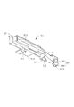
Fig. 2 is the stereographic map of a preferred embodiments of fixture among Fig. 1.
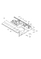
Fig. 3 is the three-dimensional assembly diagram of Fig. 1 middle shell and flexible member.
Fig. 4 is the three-dimensional assembly diagram of Fig. 1.
Fig. 5 is the three-dimensional assembly diagram of another angle of Fig. 1.
Fig. 6 is the stereographic map in the expansion board unloading process among Fig. 5.
The main element symbol description
| |
10 |
| Base plate | 11 |
| Back plate | 12 |
| Installing port | 121 |
| Side plate | 13 |
| Adapter | 20 |
| Inserted terminal | 21 |
| Converting interface | 22 |
| Fixed |
30 |
| Roof | 31 |
| |
33 |
| Expand draw-in groove | 331 |
| Sidewall | 35 |
| Fixed head | 36 |
| |
37 |
| Flexible member | 40 |
| Inserted |
41 |
| The |
42 |
| |
43 |
| |
50 |
| |
51 |
| The |
511 |
| The conflict inclined- |
512 |
| |
513 |
| |
514 |
| Sliding |
515 |
| The articulated |
52 |
| Connecting |
521 |
| The |
522 |
| |
523 |
| |
60 |
| |
61 |
| |
62 |
| |
621 |
| Spliced |
63 |
| The blocking |
64 |
| |
65 |
| |
66 |
| |
68 |
| |
681 |
| Narrow |
682 |
| The |
69 |
| The |
691 |
| The |
692 |
| |
70 |
| Slot | 71 |
| |
80 |
| First end | 81 |
| |
83 |
| Installation sheet | 85 |
| Fixed part | 851 |
| The support portion | 853 |
| The insertion section | 855 |
| The Plug Division | 87 |
Following embodiment will combine above-mentioned accompanying drawing to further specify the present invention.
Embodiment
See also Fig. 1, in a preferred embodiments of the present invention, an expansion card fixer is used for fixing an expansion board 80, comprises a casing 10, a fixed mount 30, a flexible member 40, a fixture 50, and the housing 60 that is fixed in the said casing 10.
Said expansion board 80 has one first end 81 and one and first end, 81 second opposed end 83.Said first end, 81 fixing installation sheets 85.Said installation sheet 85 comprises support portion 853 that a fixed part 851, is connected with said fixed part 851, and along a insertion section 855 that said fixed part 851 extends perpendicular to said support portion 853 directions.In one embodiment, said expansion board 80 can be a display card, video signal card, network interface card or a sound card.Said first end 81 and second end, 83 adjacent sides are established a Plug Division 87.
Said casing 10 comprises that a base plate 11, is perpendicular to the back plate 12 of said base plate 11 and the side plate 13 of a vertical said base plate 11.Said back plate 12 is provided with an installing port 121.One mainboard 70 is fixed on the said base plate 11.Said mainboard 70 comprises a slot 71.
Said fixed mount 30 comprises a roof 31, a rear wall 33 and a sidewall 35.Said rear wall 33 is offered some expansion draw-in grooves 331, and from parallel and away from the one edge of said sidewall 35 along extending a fixed head 36, in order to the installation sheet 85 of fixing said expansion board 80 perpendicular to said rear wall 33 directions.Said sidewall 35 is offered the interface 37 of the insertion section 855 of a corresponding said installation sheet 85.One adapter 20 is fixed on the said sidewall 35, and said adapter 20 is provided with the inserted terminal 21 of slot 71 of converting interface 22 and a corresponding said mainboard 70 of the Plug Division 87 of a corresponding said expansion board 80.Said rear wall 33 and sidewall 35 are provided with plurality of fixed hole (figure does not show).Utilize locking part, like screw etc., passing said fixed orifice can be installed in said fixed mount 30 on the said base plate 11.
Said flexible member 40 comprises the elastic arm 43 that the location division that takes the shape of the letter U 42 and that an inserted terminal 41, connects said inserted terminal 41 extends to form from said location division 42.
Please continue to consult Fig. 2, said fixture 50 comprises a main part 51, from articulated section 52 that a side of said main part 51 extends to form and the clamping part 53 that extends to form from the opposite side of said main part 51, and said clamping part 53 is wedge shape.Said articulated section 52 comprises that the connecting portion 521 that extends to form from said main part 51 and is from holding section 522 that said connecting portion 521 extends to form.The cross-sectional area of said holding section 522 is greater than the cross-sectional area of said connecting portion 521, and said articulated section 52 is provided with a fluting 523 said connecting portion 521 and said holding section were opened two halves in 522 minutes.Said fixture 50 also comprises one from contact part 511 that said main part 51 extends to form.Said contact part 511 be provided with one be used to conflict said flexible member 40 the conflict inclined-plane 512 of elastic arm 43.Said main part 51 is provided with a mounting groove 513, and said fixture 50 also comprises an operating portion 514 and the sliding part 515 that said main part 51 extends to form.Said sliding part 515 is L-shaped.
See also Fig. 3, said housing 60 has the pivot part 62 that an enclosure body 61, extends to form on said enclosure body 61.Said pivot part 62 is provided with the pivoting hole 621 of a corresponding said holding section 522.Said enclosure body 61 be provided with one be used to peg graft said flexible member 40 the spliced eye 63 of inserted terminal 41.Said housing 60 also comprises one first installation sheet 65 and one second installation sheet 66.Said first installation sheet 65 and second installation sheet 66 all become L shaped, are used to locate the location division 42 of said flexible member 40.The orientation of said first installation sheet 65 and second installation sheet 66 is vertical.Said housing 60 also comprises a blocking part 64.Said enclosure body 61 is provided with a slip mouth 68.Said slide mouthfuls 68 comprises that one can hold wide 681 and one that said sliding part 515 passes and is used to hold the narrow long portion 682 that said sliding part 515 slides therein.Said housing 60 also comprises a locking part 69, and said locking part 69 comprises that one engages the press section 692 that the auxiliary section 691 and of said clamping part 53 extends to form from said auxiliary section 691 from said enclosure body 61 being used to of extending to form.
Please continue to consult Fig. 3 to Fig. 6, the inserted terminal 41 of said flexible member 40 is plugged in the spliced eye 63 of said housing 60, and said location division 42 is installed on said first installation sheet 65 and second installation sheet 66.Articulated section 52 with said fixture 50 is articulated in the said pivoting hole 621 again, makes said sliding part 515 be in said the slip in mouthfuls 68 wide 681, and the elastic arm 43 of said flexible member 40 is contacted on the conflict inclined-plane 512 of said fixture 50.Said housing 60 is fixed on the base plate 11 of said casing 10 through locking part (figure does not show).
When said expansion board 80 is installed on said fixed mount 30, the installation sheet 85 of said expansion board 80 is inserted along said expansion draw-in groove 331.Insert in the interface 37 of said sidewall 35 said insertion section 855, and said Plug Division 87 is inserted in the converting interface 22 of said adapter 20.Said fixed part 851 is resisted against on the said fixed head 36, and locks together through locking parts such as screws.
When being installed on said fixed mount 30 in the said casing 10, in the slot 71 that the inserted terminal 21 of said adapter 20 inserts on the said mainboard 70, second end 83 of said expansion board 80 is taken on the enclosure body 61 that is placed on said housing 60.Rotating said fixture 50 makes the clamping part 53 of said fixture 50 engage with the auxiliary section 691 of the locking part 69 of said housing 60; At this moment; Said second end 83 is contained in the mounting groove 513 of said main part 51, and elastic arm 43 elasticity of said flexible member 40 contact on the conflict inclined-plane 512 of said fixture 50.Said sliding part 515 is in the narrow long portion 682 of the said mouth 68 that slides.Said fixture 50 rotates in the plane of a parallel said expansion board 80.
During dismounting; Push the press section 692 of said housing 60 and drive said auxiliary section 691 and separate with said clamping part 53; Elastic arm 43 recovery of elasticity of said flexible member 40 and fixture 50 is rotated away from said expansion board 80; Said expansion board second end 83 is separated with said fixture 50, remove the locking part of said installation sheet 85 and said fixed head 36 again, just can said expansion board 80 be pulled down from said casing 10.
Claims (10)
1. expansion card fixer; Be used for fixing an expansion board; Comprise a casing and be installed on a fixed mount and the housing in the said casing; Said fixed mount is used for fixing one first end of said expansion board; It is characterized in that: said expansion card fixer comprises that also a fixture and is installed on the flexible member on the said housing; Said fixture comprises a main part, from articulated section that one first side of said main part extends to form and the clamping part that extends to form from one of said main part second side relative with said first side, and said articulated section is articulated on the said housing, and said housing comprises the locking part of an enclosure body and a corresponding said clamping part; Said clamping part is used for rotation in the plane of a parallel said expansion board and engages said locking part; So that one second end of said expansion board is contained in the mounting groove of said main part, said flexible member comprises that an elasticity contacts at the elastic arm on the said fixture, and said elastic arm is used for when said clamping part separates with said locking part, relying on elastic force and flicks said fixture.
2. expansion card fixer as claimed in claim 1; It is characterized in that: said housing also comprises one first installation sheet that extends to form from said enclosure body; Said housing is provided with a spliced eye; Said flexible member comprises that one is plugged in the inserted terminal in the said spliced eye, the location division of the said inserted terminal of a connection and the said elastic arm that extends to form from said location division, and said first installation sheet is located said location division.
3. expansion card fixer as claimed in claim 2; It is characterized in that: said housing also comprises second installation sheet that extends to form from said enclosure body; The orientation of said first installation sheet and said second installation sheet is vertical; Said location division takes the shape of the letter U, and said first installation sheet and said second installation sheet are located said location division.
4. expansion card fixer as claimed in claim 1 is characterized in that: said housing also comprises a blocking part, and said blocking part is used for when said fixture flicks, keeping out said fixture.
5. expansion card fixer as claimed in claim 1 is characterized in that: said fixture is provided with a conflict inclined-plane, and said elastic arm elasticity contacts on the said conflict inclined-plane.
6. expansion card fixer as claimed in claim 1; It is characterized in that: said fixture comprises a sliding part; Said housing is provided with a slip mouth; The said mouth that slides comprises wide and the narrow long portion that the said sliding part of a guiding slips into, and said sliding part is used to pass said wide and slip into said narrow long portion.
7. expansion card fixer as claimed in claim 1 is characterized in that: said sliding part is L-shaped.
8. expansion card fixer as claimed in claim 1; It is characterized in that: said articulated section comprises that a junction and is from holding section that said connecting portion extends to form; The cross-sectional area of said holding section is greater than the cross-sectional area of said connecting portion, and said housing is provided with the pivoting hole of a corresponding said holding section.
9. expansion card fixer as claimed in claim 1 is characterized in that: said articulated section is provided with a fluting, and said fluting separates two halves with said connecting portion and said holding section.
10. expansion card fixer as claimed in claim 1; It is characterized in that: said locking part comprises the press section that the auxiliary section and of the said clamping part of an engaging extends to form from said auxiliary section, pushes said press section said auxiliary section is separated with said clamping part.
Priority Applications (3)
| Application Number | Priority Date | Filing Date | Title |
|---|---|---|---|
| CN201110171306.XA CN102841650A (en) | 2011-06-23 | 2011-06-23 | Expansion card fixing device |
| TW100122550A TW201302007A (en) | 2011-06-23 | 2011-06-28 | Mounting apparatus for expansion card |
| US13/425,387 US8634187B2 (en) | 2011-06-23 | 2012-03-20 | Mounting apparatus for PCI card |
Applications Claiming Priority (1)
| Application Number | Priority Date | Filing Date | Title |
|---|---|---|---|
| CN201110171306.XA CN102841650A (en) | 2011-06-23 | 2011-06-23 | Expansion card fixing device |
Publications (1)
| Publication Number | Publication Date |
|---|---|
| CN102841650A true CN102841650A (en) | 2012-12-26 |
Family
ID=47361652
Family Applications (1)
| Application Number | Title | Priority Date | Filing Date |
|---|---|---|---|
| CN201110171306.XA Pending CN102841650A (en) | 2011-06-23 | 2011-06-23 | Expansion card fixing device |
Country Status (3)
| Country | Link |
|---|---|
| US (1) | US8634187B2 (en) |
| CN (1) | CN102841650A (en) |
| TW (1) | TW201302007A (en) |
Cited By (1)
| Publication number | Priority date | Publication date | Assignee | Title |
|---|---|---|---|---|
| CN113672048A (en) * | 2020-05-15 | 2021-11-19 | 佛山市顺德区顺达电脑厂有限公司 | Network card mounting mechanism |
Families Citing this family (3)
| Publication number | Priority date | Publication date | Assignee | Title |
|---|---|---|---|---|
| CN104571318B (en) * | 2014-12-05 | 2018-02-23 | 英业达科技有限公司 | Electronic installation and its fixed module |
| TWI714251B (en) * | 2019-09-09 | 2020-12-21 | 英業達股份有限公司 | Fixing structure |
| WO2024080999A1 (en) * | 2022-10-14 | 2024-04-18 | Hewlett-Packard Development Company, L.P. | Card connectors |
Family Cites Families (3)
| Publication number | Priority date | Publication date | Assignee | Title |
|---|---|---|---|---|
| US6920048B2 (en) * | 2003-12-15 | 2005-07-19 | Dell Products L.P. | Low profile expansion card retaining clip |
| JP4603459B2 (en) * | 2005-10-14 | 2010-12-22 | 富士通株式会社 | Card unit |
| US8144463B2 (en) * | 2010-04-08 | 2012-03-27 | Dell Products L.P. | Card retention system |
-
2011
- 2011-06-23 CN CN201110171306.XA patent/CN102841650A/en active Pending
- 2011-06-28 TW TW100122550A patent/TW201302007A/en unknown
-
2012
- 2012-03-20 US US13/425,387 patent/US8634187B2/en not_active Expired - Fee Related
Cited By (2)
| Publication number | Priority date | Publication date | Assignee | Title |
|---|---|---|---|---|
| CN113672048A (en) * | 2020-05-15 | 2021-11-19 | 佛山市顺德区顺达电脑厂有限公司 | Network card mounting mechanism |
| CN113672048B (en) * | 2020-05-15 | 2024-04-19 | 佛山市顺德区顺达电脑厂有限公司 | Network card mounting mechanism |
Also Published As
| Publication number | Publication date |
|---|---|
| US20120327578A1 (en) | 2012-12-27 |
| US8634187B2 (en) | 2014-01-21 |
| TW201302007A (en) | 2013-01-01 |
Similar Documents
| Publication | Publication Date | Title |
|---|---|---|
| CN201138902Y (en) | Expansion card fixer | |
| US20130127310A1 (en) | Bracket of electronic device, draw set assembly of electronic device, and computer case | |
| US7701725B2 (en) | Computer system with riser card | |
| JPH11513190A (en) | Small card docking connector | |
| CN104281230A (en) | Electronic device and expansion card module thereof | |
| CN102566692B (en) | Expansion card fixer | |
| US20160309608A1 (en) | Storage unit and electronic device having the same | |
| CN102841650A (en) | Expansion card fixing device | |
| CN1204475C (en) | Notebook-type computer | |
| WO2021017542A1 (en) | Fixing device and computer apparatus | |
| CN102841657A (en) | Expansion card fixing device | |
| CN102541194A (en) | Expansion card fixing device | |
| CN101034303A (en) | Electronic component pushing in device | |
| CN105988506B (en) | Electronic device | |
| CN102736697B (en) | Expansion card fixer | |
| CN101930262A (en) | Extension card fixing device | |
| US11132034B2 (en) | Electronic device fastener | |
| CN102385423A (en) | Electronic device | |
| TWM311166U (en) | Guide member for electrical connection | |
| TW201228143A (en) | Mounting apparatus for expansion card | |
| CN102103395B (en) | Expansion card locking device | |
| WO2020107158A1 (en) | Hub | |
| US20100124014A1 (en) | Retaining device for peripheral card | |
| CN102200804A (en) | CD-ROM (compact disc read-only memory) fixing mechanism and electronic device using same | |
| US20140308840A1 (en) | Usb flash drive positioning structure |
Legal Events
| Date | Code | Title | Description |
|---|---|---|---|
| C06 | Publication | ||
| PB01 | Publication | ||
| C02 | Deemed withdrawal of patent application after publication (patent law 2001) | ||
| WD01 | Invention patent application deemed withdrawn after publication |
Application publication date: 20121226 |