CN102802804A - Disposal Separator/concentrator Device And Method Of Use - Google Patents
Disposal Separator/concentrator Device And Method Of Use Download PDFInfo
- Publication number
- CN102802804A CN102802804A CN2010800277122A CN201080027712A CN102802804A CN 102802804 A CN102802804 A CN 102802804A CN 2010800277122 A CN2010800277122 A CN 2010800277122A CN 201080027712 A CN201080027712 A CN 201080027712A CN 102802804 A CN102802804 A CN 102802804A
- Authority
- CN
- China
- Prior art keywords
- chamber
- valve
- starter
- fluid sample
- centrifugal
- Prior art date
- Legal status (The legal status is an assumption and is not a legal conclusion. Google has not performed a legal analysis and makes no representation as to the accuracy of the status listed.)
- Pending
Links
Images


Classifications
-
- B—PERFORMING OPERATIONS; TRANSPORTING
- B04—CENTRIFUGAL APPARATUS OR MACHINES FOR CARRYING-OUT PHYSICAL OR CHEMICAL PROCESSES
- B04B—CENTRIFUGES
- B04B11/00—Feeding, charging, or discharging bowls
- B04B11/04—Periodical feeding or discharging; Control arrangements therefor
-
- B—PERFORMING OPERATIONS; TRANSPORTING
- B01—PHYSICAL OR CHEMICAL PROCESSES OR APPARATUS IN GENERAL
- B01D—SEPARATION
- B01D21/00—Separation of suspended solid particles from liquids by sedimentation
- B01D21/26—Separation of sediment aided by centrifugal force or centripetal force
- B01D21/262—Separation of sediment aided by centrifugal force or centripetal force by using a centrifuge
-
- B—PERFORMING OPERATIONS; TRANSPORTING
- B04—CENTRIFUGAL APPARATUS OR MACHINES FOR CARRYING-OUT PHYSICAL OR CHEMICAL PROCESSES
- B04B—CENTRIFUGES
- B04B5/00—Other centrifuges
- B04B5/04—Radial chamber apparatus for separating predominantly liquid mixtures, e.g. butyrometers
- B04B5/0407—Radial chamber apparatus for separating predominantly liquid mixtures, e.g. butyrometers for liquids contained in receptacles
- B04B5/0414—Radial chamber apparatus for separating predominantly liquid mixtures, e.g. butyrometers for liquids contained in receptacles comprising test tubes
- B04B5/0421—Radial chamber apparatus for separating predominantly liquid mixtures, e.g. butyrometers for liquids contained in receptacles comprising test tubes pivotably mounted
-
- G—PHYSICS
- G01—MEASURING; TESTING
- G01N—INVESTIGATING OR ANALYSING MATERIALS BY DETERMINING THEIR CHEMICAL OR PHYSICAL PROPERTIES
- G01N1/00—Sampling; Preparing specimens for investigation
- G01N1/28—Preparing specimens for investigation including physical details of (bio-)chemical methods covered elsewhere, e.g. G01N33/50, C12Q
- G01N1/2813—Producing thin layers of samples on a substrate, e.g. smearing, spinning-on
-
- G—PHYSICS
- G01—MEASURING; TESTING
- G01N—INVESTIGATING OR ANALYSING MATERIALS BY DETERMINING THEIR CHEMICAL OR PHYSICAL PROPERTIES
- G01N15/00—Investigating characteristics of particles; Investigating permeability, pore-volume, or surface-area of porous materials
- G01N15/04—Investigating sedimentation of particle suspensions
- G01N15/042—Investigating sedimentation of particle suspensions by centrifuging and investigating centrifugates
-
- G—PHYSICS
- G01—MEASURING; TESTING
- G01N—INVESTIGATING OR ANALYSING MATERIALS BY DETERMINING THEIR CHEMICAL OR PHYSICAL PROPERTIES
- G01N15/00—Investigating characteristics of particles; Investigating permeability, pore-volume, or surface-area of porous materials
- G01N15/04—Investigating sedimentation of particle suspensions
- G01N15/05—Investigating sedimentation of particle suspensions in blood
-
- B—PERFORMING OPERATIONS; TRANSPORTING
- B01—PHYSICAL OR CHEMICAL PROCESSES OR APPARATUS IN GENERAL
- B01L—CHEMICAL OR PHYSICAL LABORATORY APPARATUS FOR GENERAL USE
- B01L3/00—Containers or dishes for laboratory use, e.g. laboratory glassware; Droppers
- B01L3/50—Containers for the purpose of retaining a material to be analysed, e.g. test tubes
- B01L3/502—Containers for the purpose of retaining a material to be analysed, e.g. test tubes with fluid transport, e.g. in multi-compartment structures
-
- G—PHYSICS
- G01—MEASURING; TESTING
- G01N—INVESTIGATING OR ANALYSING MATERIALS BY DETERMINING THEIR CHEMICAL OR PHYSICAL PROPERTIES
- G01N35/00—Automatic analysis not limited to methods or materials provided for in any single one of groups G01N1/00 - G01N33/00; Handling materials therefor
- G01N2035/00465—Separating and mixing arrangements
- G01N2035/00495—Centrifuges
Abstract
The present invention relates to methods, devices and systems for separation and concentration of particles from liquid and fluid samples. In some embodiments, the separation/concentration is achieved by sequential centrifugation steps. In particular, one aspect of the invention relates to a separation/concentration device which comprises at least a first chamber (101) and a second chamber (103) connected by a first valve (111), whereby operation of the first valve controls the material transfer from the first chamber to the second chamber. In some embodiments, valve operation can be manually, semi -manually or automatically. Other aspects of the invention relate to single- or multi-chambered separation/concentrator devices, and methods and systems for use. Other aspects of the invention relate to devices for operation of the valves, e.g., semi -manual actuation devices, and automatic inertial activation devices and mechanical actuation devices present in purpose-built centrifuges.
Description
The cross reference of related application
The application requires the U.S. Provisional Patent Application No.61/174 that submits on May 1st, 2009 according to 35U.S.C. § 119 (e), 664 with U.S. Provisional Patent Application No.61/174,698 rights and interests, at this full content of incorporating them into as a reference.
Background technology
Be used to diagnose the bacterial infection of water or food supply or the current standard of germ contamination to require purer bacterial cultures sample relatively.In order to obtain this culture, the bacterium in the sample must be in the laboratory outside the venue of special use in special culture medium grow overnight.Then, the bacterium that utilizes biochemical test to discern to exist in the culture.This program labour intensity is big, requires skilled laboratory technicians, and has introduced the human error element.Cell cultivation itself is also very consuming time, and possibly need several days or even a few week incubation growth bacterium, for example Mycobacterium tuberculosis (Much's bacillus) slowly.
The replacement method and/or the equipment that quicken said procedure and reduce relevant work been have have been researched and developed.
Summary of the invention
The present invention relates to a kind of from liquid or fluid sample, concentrating and particle or the cell separation and the enrichment facility of separating particles (for example, bacterium or pollutant).Centrifugation step through continuous realizes isolation/concentration.This separator/inspissator device helps rapid extraction or concentrated bacterium or particle from fluid sample (for example, water) or biological fluid sample (for example, blood), and provide can be with the concentrated sample of post processing or analysis.Because producing, separator disclosed herein/inspissator device concentrates sample; Thereby (for example cause usually from the particulate of sample; From bacterium such as fluid samples such as blood or other biological fluids) by purifying with separate; Use concentrated sample so this separator/inspissator device also helps producing the analysis that is used for the downstream diagnostic assay, for example, be used for PCR, bioMEMS device etc.
In one embodiment; The present invention relates to a kind of disposable apparatus (this paper is called " separator/inspissator " device); Wherein can in a plurality of centrifugation step, carry out particle separation, and sample can be delivered to another chamber from a chamber in each centrifugation step process in disposable apparatus.Can control sample flowing through the valve between each chamber, wherein,,, for example manually or automatically operate through various mechanism operated valve as disclosed herein from a chamber to another chamber.
One aspect of the present invention relates to and a kind ofly from fluid sample, separating and the device of concentrated particulate through centrifugal action, for example, and disposable apparatus.In certain embodiments, said device comprises: (a) at least one first chamber and at least one second chamber, and wherein first chamber has the inlet that is used for the inlet flow sample body and is positioned at the outlet that is used for fluid is outputed to valve of first cavity bottom; Second chamber has and is used for receiving the inlet of fluid and being positioned at the output of cavity bottom from valve; (b) first passage, first passage connect the output of first chamber and the input of second chamber; (c) be housed in the first interior valve of first passage, wherein first valve comprises collection container and control material flowing from first chamber to second chamber.In certain embodiments, valve is the metering valve that comprises collection container.In optional embodiment, said device can comprise any amount of further chambers, for example, the 3rd or multi-cavity chamber more, wherein each chamber vertical array and each the chamber utilization passage of accommodating valve is connected with adjacent chamber.In certain embodiments, second chamber comprises the outlet that is connected with the second channel with second valve, and second channel can be connected with the one or more further chambers in multi-cavity disclosed herein chamber separator/inspissator device.
In optional embodiment, second chamber is as collection chamber, and collects the sample that concentrates (for example, second chamber for example can be the collection chamber in the 2-chamber device).In these embodiment, second chamber can be configured to any collection chamber, for example; Any pipe (for example; 0.2ml pipe or 0.5ml pipe or 1.5ml pipe or 2.0ml pipe) or be used to collect any geometrical construction that concentrates sample, for example, collection chamber has the slide that is used for collecting from the outlet of first passage the indenture of sample; For example, microslide.In certain embodiments, as second chamber of collection chamber or below chamber (for example, the 3rd, the 4th, the 5th chamber etc.) can after collecting sample, take off from separator/inspissator device.
In certain embodiments; Have first chamber and second chamber separator/the inspissator device (for example; See Figure 1A) have and be used for material is transferred to the following general operation pattern of second chamber from first chamber, wherein require three valve operations and continuous centrifugal circulation (this paper is called " 3-valve operation method "):
Step 1: carry out valve is moved to first valve operation of position 3, wherein valve is aimed at, thereby the collection container of valve flow to second chamber to prevent material from first chamber to the outlet sealing of first chamber.
Step 2: fluid sample that will be to be separated is added to the inlet of first chamber and carries out the first centrifugal circulation.The valve that is positioned at position 3 stops the outlet flow valve collection container of material from first chamber, thus make first centrifugal cycle period material be collected in the bottom of first chamber.
Step 3: carry out valve is moved to second valve operation of position 1, the second centrifugal circulation is carried out in wherein the outlet that the outlet of first chamber is opened wide and aimed at first chamber of the collection container in the valve then.The valve that is arranged in position 1 makes the collection container that material is collected in valve in the second centrifugal cycle period.
Step 4: carry out valve is moved to the 3rd valve operation of position 2, wherein the collection container in the valve opens wide and aims at the inlet of second chamber to the inlet of second chamber, carries out the 3rd centrifugal circulation then.The valve that is positioned at position 2 make the 3rd centrifugal cycle period material transfer to second chamber from the collection container of valve.
(for example have more than two chambers; Three chambers) or among the embodiment more than three chambers; Except omitting fluid sample being added to first chamber of step 2, through repeating three valve operations and centrifugal circulation step 1-4 transfers to each follow-up chamber with particle matter.
In optional embodiment, can use two valve operations and follow-up centrifugal circulation, use the more efficient operation pattern that material is transferred to second chamber from first chamber, for example may further comprise the steps (this paper is called " 2-valve operation method "):
Step 1: carry out valve is moved to first valve operation of position 1, wherein the collection container in the valve is aimed at the outlet of first chamber.
Step 2: fluid sample that will be to be separated is added to the inlet of first chamber and carries out the first centrifugal circulation.The valve that is arranged in position 1 make first centrifugal cycle period material be collected in the collection container of valve.
Step 3: carry out valve is moved to second valve operation of position 2, wherein the collection container in the valve is aimed at the inlet of second chamber, and carries out the second centrifugal circulation.The valve that is positioned at position 2 make second centrifugal cycle period material transfer to second chamber from the collection container of valve.
(for example have more than two chambers; Three chambers) or among the embodiment more than three chambers; Valve operation and centrifugal circulation step 1-3 (fluid sample being added to first chamber except omitting) through repeating 2-valve operation method transfer to each follow-up chamber with particle matter; Wherein before 1 be operated to position 2 after rotation and in second rotation, so that particulate is transferred to lower chamber from upper chamber from the position at the valve between two chambers.
Comprise at separator/inspissator device among some embodiment of a plurality of chambers (for example, three or four or five or multi-cavity chamber more), utilize the valve between each chamber; Can use identical valve operation method to control material flowing from a chamber to next chamber; For example, can use 3-valve operation method to operate all valves, perhaps can use more effective 2-valve operation method to operate all valves; Perhaps selectively; In certain embodiments, use some valves in the 3-valve operation method operating means, use more effective 2-valve operation method to operate some valves in this device.
Another aspect of the present invention relates to the method for the particle in a kind of separation of the fluid sample, and the fluid sample that wherein will separate is placed in first (for example, top) chamber and to separator/inspissator device and carries out centrifugal action.Be arranged in some embodiment of position 1 at valve in centrifugal cycle period, make particulate matter form bead/sedimentation through increasing gravity, and be deposited in the bottom of first (for example, top) chamber.Be arranged in some embodiment of position 2 at valve in centrifugal cycle period, particulate matter deposit come out from the collection container of valve and get into the perhaps input of other downstream chambers of second chamber through increasing gravity.
Chamber
In certain embodiments, valve can be constructed with and be used to regulate the collection container of amount of transferring to the particle of lower chamber from upper chamber.For example, in certain embodiments, when for example manually, when partly manually or automatically operated valve makes the outlet of position alignment upper chamber of collection container (for example, position 1), the valve collection container is collected predetermined or predetermined particulate matter in centrifugal cycle period.When for example manually, when partly manually or automatically operated valve makes the inlet of position alignment second (or bottom) chamber of valve collection container (for example, position 2), the sedimented particle in the valve collection container deposited in second chamber in centrifugal cycle period.
In certain embodiments; Separator/inspissator device can comprise at least two chambers; Or at least three chambers; And have among the embodiment of three chambers at separator/inspissator, can use any combination of 2-disclosed herein or 3-valve operation method that particle is transferred to second chamber from first chamber, and transfer to the 3rd chamber from second chamber.
In the embodiment shown in this paper, each chamber can be configured to collect particulate matter (for example, the bead of material); For example; Chamber can be configured to funnel shaped, and to be used for the particle of sedimentation is guided to the outlet of the bottom that is positioned at top chamber, the passage that is connected with following chamber is led in this outlet.
In certain embodiments, first chamber design becomes maintenances to need the volume of the fluid of separation, and the scope of this volume can be received and rise to 10L for 10.In certain embodiments, first chamber design becomes to keep the volume of 100ml to 1L, or any integer between about 100ml to 1L.In one embodiment, the scope of volume can for 1ml approximately at least to about 10ml, or approximately at least 10ml to about 100ml, or about 100ml about 500ml extremely, or about 500ml about 1L extremely, or about 10 receive and rise to 100 microlitres.In other embodiments, the scope of volume can be 10 microlitres to 20 milliliter or any integer between them.In certain embodiments, volume can be about 10ml, or about 100ml.Any fluid that contains insoluble particles be can use, for example, the whole blood of haemocyte or bacterium, the Chi Shui/river that contains microorganism and urine contained.
In embodiment as herein described, first (for example, top) chamber can be designed to comprise be positioned at the top wide opening (for example; Input); Being easy to fluid input, and comprise that the funnel that is positioned at cavity bottom (sees that Fig. 7-Fig. 8), this funnel leads to and channel attached outlet; Wherein the inlet of passage and follow-up bottom (for example, second or bottom) chamber connects.
Can correspondingly regulate the size and dimension of chamber and passage, with type, volume and the size of the type of fluid that meets the needs of separation, the particle that will collect and required collected volume.
In one embodiment, below (for example, second, third or bottom) chamber less than first (for example, top or other higher) chamber.In one embodiment, bottom chamber can contain cleaning solution or the suspension that the spherical particle of collection is used.In certain embodiments, each chamber can be filled with the fluid sample of collection, for example second fluid sample or the 3rd fluid sample, for example buffer solution or water.
In certain embodiments, below chamber (for example, second chamber in the 2-chamber device or the 3rd chamber in the 3-chamber device etc.) can be used as collection chamber, and collects concentrated sample.This collection chamber has the input that is used to receive sample usually, but is not used in the output that sample flows out.In certain embodiments, collection chamber can be configured to any collection chamber, for example; Any collecting pipe (for example; 0.2ml pipe or 0.5ml pipe or 1.5ml pipe or 2.0ml pipe) or be used to collect the collection chamber of any geometrical construction that concentrates sample, for example, collection chamber has the slide of collecting the indenture of sample from the outlet of first passage; For example, microslide.In certain embodiments, as second chamber of collection chamber or below chamber (for example, the the 3rd of the multi-cavity chamber device the, the 4th, the 5th chamber etc.) can after collecting sample, take off from separator/inspissator device.In certain embodiments, collection chamber separates with device and can be connected on separator/inspissator device.Only comprise among some embodiment of first chamber and first valve at for example device; Device can be configured to collection chamber is connected the bottom of 1-chamber-1-valving; Make collection chamber to receive sample, and wherein control the fluid that gets into collection chamber and shift through the operation of first valve from the output of first chamber.
Valve
In certain embodiments, valve is configured to comprise collection container.In certain embodiments, when valve was positioned at position 1, the valve collection container was arranged in the position that the inlet of upper chamber is opened wide and can receives particle matter (for example, spherical material) (seeing Figure 1A) from the fluid sample of upper chamber.Through making valve move to the valve operation of position 2, the valve collection container is positioned at the position that the inlet to second (for example, bottom) chamber opens wide and can particle matter be deposited in the lower chamber.
In certain embodiments, for example, see Figure 1A, through sliding shutter (for example, in passage with the linear movement mode) make valve from a position to another position the valve operation of (for example, 3 to the position 1 from the position, and from the position 1 to the position 2).In these embodiment, valve can comprise collection container, and for example, like Figure 1A and shown in Figure 5, collection container can be configured to the groove in the valve.
In optional embodiment, for example, see Figure 1B, can make the valve operation of valve through rotating mechanism from a position to another position.In these embodiment; Valve can comprise collection container; Collection container be configured in the valve the space (for example; Indenture), wherein can be in passage changeover valve with valve for example from the position 1 move to position 2 (for example, through rotation make collection container from the outlet of aiming at upper chamber and to its position of opening wide move to the inlet of aligned with lower chamber and to its position of opening wide).At the valve collection container is among the embodiment in the space (for example, indenture) in the valve, and the valve that is positioned at position 2 is also simultaneously as the valve that is positioned at position 3 (valve that for example, is positioned at position 3 is the valve to the outlet sealing of upper chamber).Used among the embodiment of rotating mechanism at valve operation, the output of upper chamber and the input of lower chamber are arranged in the same vertical plane (seeing Figure 1B) usually.
In certain embodiments, valve operation can be the linear movement mode, for example pulls motion or ahead running.In other embodiments, valve operation can be a rotary movement, for example through the rotation knob.Can through disclosed herein any manually, half manually or auto-starter carry out valve operation.
In certain embodiments, can for example use cam sleeve starting drive disclosed herein to come manually or operated valve manually partly.In optional embodiment, can for example use inertia-activated mechanism disclosed herein operated valve automatically, wherein between centrifugal deceleration period, start valve.In optional embodiment, use the external arm that is arranged in special centrifugal machine automatically to start valve, wherein, centrifuge starts valve after stopping fully.
In one embodiment, with hand mobile valve and manually not by starting drive (for example half manually cam sleeve starting drive or automatic starting device).In one embodiment, by or not by the situation of instrument (bar that for example, leads to the valve in the passage separately) under with hand operated valve manually.In this embodiment, after centrifugal action stops, with hand operated valve manually.
In one embodiment, for example use partly operated valve manually of cam sleeve device disclosed herein.In optional embodiment, can use the cam sleeve device to come operated valve, this cam sleeve device is operably connected with disposable separator/inspissator device, comes operated valve with the manual rotating mechanism that utilizes the cam sleeve device.In one embodiment, can come operated valve through the cam sleeve starting drive that is operatively connected that after centrifugal action stops, manually moving with hand.
In one embodiment, for example can be through the starting drive (for example, inertia-activated mechanism disclosed herein) that can be operatively connected operated valve automatically.In one embodiment, starting drive uses piston to come operated valve.In one embodiment, the deceleration period of centrifuge chien shih come operated valve with inertia-activated mechanism.Between deceleration period, inertia-activated mechanism presses against piston on the valve, thus the valve in the operating walk way.Therefore, in certain embodiments, the decelerating phase of centrifugal circulation (for example) mobile valve automatically during centrifugal action for example.For example, in having the 3-chamber device of two valves, mobile valve sequentially, that is, operation upper part valve between the deceleration period of first centrifugal action, and in the deceleration manipulate bottom of the second follow-up centrifugal action valve.In certain embodiments, inertia-activated mechanism can cooperate with the rotor or the machine basket that use in the commercially available centrifuge, and perhaps in optional embodiment, inertia-activated mechanism can be assembled in the special centrifugal machine.
In one embodiment, come operated valve automatically through starting drive (for example, seeing Figure 28) as the special centrifugal machine parts.In certain embodiments; Starting drive can be any mechanism that is used to start valve; For example; Said mechanism includes but not limited to motor, solenoid, pump, mechanical pump, lever, cylinder starting drive disclosed herein, and this starting drive has the external arm of the valve in operation disposable separator/inspissator device.In this embodiment; At least one separator/inspissator device is arranged in the rotor of special centrifugal machine; The starting drive (for example, the external arm of mechanical starting device) that make to connect centrifuge is in each centrifugal cycle period or can cooperate with the valve of disposable separator/inspissator device afterwards.In these embodiment, the mechanism of use connection centrifuge is operated valve automatically.In certain embodiments, mobile valve automatically, for example, wherein separator/inspissator device stops after centrifugal circulation and in centrifuge, is positioned at the position that will cooperate with the external arm of mechanical starting device so that operate one or more valves.For example, in having the 3-chamber device of two valves, each valve can sequentially be operated, and can accomplish first centrifugal circulation operation upper part valve afterwards, and can after follow-up centrifugal circulation, operate the bottom valve.
In one embodiment, valve comprises collection container, and operated valve moves it in the passage that connects two chambers, thereby allows designated volume to transfer to the chamber of valve below from the chamber of valve top.The volume that is shifted is by the decision of the volume of valve collection container, and depends on type, volume, quality and the size of particle to be collected and required collected volume, and the volume that is shifted can be any amount.For example, the volume of valve collection container and thereby the volume that between each chamber, shifts can be at least 10 receiving and rise to 10 milliliters approximately.If the use metering valve for example has the valve of measuring tank collection container or metering space collection container, wherein collection container allows to shift at least more than the 10nl; For example, about 5 μ l, or about 10 μ l; Or about 100 μ l, or about 1ml, or about 2ml; Or 2ml to 10ml, or any integer between the 10nl to 10ml, then can confirm the volume that between each chamber, shifts in advance.In certain embodiments; Volume is generally confirmed by the volume of the collection container that exists in the valve; The sample that collection container receive to be collected from upper chamber (for example; When valve is positioned at position 1), and collection container is assigned to lower chamber (for example, when valve is positioned at position 2) with the sample volume of collecting (in collection container) subsequently.
System according to the present invention provides a kind of and from fluid sample, has separated and the system of concentrated particulate through centrifugal action; Said system comprises: (a) first chamber and second chamber; Wherein first chamber has and is used to apply the ingate of fluid sample and the outlet of interface channel; And second chamber has the inlet of interface channel, and (b) valve, said valve are positioned at the passage that connects each chamber; (c) centrifuge.Another embodiment of piece-rate system comprises the valve starting device of separator as herein described/inspissator device, operated valve, for example, and half manual starter (for example, cam sleeve starting drive) or auto-starter (for example, inertia-activated mechanism).In certain embodiments, said system also comprises centrifuge.In one embodiment, valve operating device is the automatic valve operating means, for example, and inertia-activated mechanism.
An alternative embodiment of the invention is a kind ofly from fluid sample, to separate and the method for concentrated particulate through centrifugal action, and said method comprises: (a) with pack into first chamber of multi-cavity chamber separator of fluid sample; (b) fluid sample in first chamber is carried out centrifugal action, particulate is separated from fluid sample and accumulate in first chamber; (c) operated valve flows into second chamber with at least a portion of the particulate that allows to gather in first chamber; (d) particulate that gathers in second chamber is carried out centrifugal action, particulate is further separated from fluid sample and accumulate in second chamber.
In another embodiment; Embodiments of the invention are a kind ofly from fluid sample, to separate and the method for concentrated particulate through centrifugal action; Said method comprises: (a) generator; Said device has first chamber that is connected with second chamber through passage, and said passage comprises valve, and said valve can prevent that material from flowing between first chamber and second chamber; The fluid sample that (b) will contain particulate injects first chamber; (c) said device is carried out centrifugal action and continues the scheduled time, particulate is separated from fluid sample and accumulate near the outlet of first chamber; (d) operated valve makes the particulate of separation move to second chamber from first chamber; (e) said device is carried out centrifugal action and continues the scheduled time, particulate is further separated from fluid sample and accumulate near the outlet of second chamber.
Utilize separator disclosed herein/inspissator device to come the another kind of method of separating particles to comprise: the fluid sample that (a) will contain particulate injects first chamber of disposable separator/inspissator device; Wherein first chamber has the inlet that is used to receive sample; First chamber is connected with second chamber through passage, and said passage comprises valve; In centrifuge, piece-rate system is carried out centrifugal action; Wherein for example (for example can use manual operation; Use hand) or (for example use half manual operation; Use cam sleeve starting drive disclosed herein) or through automatically operation (for example, deceleration period chien shih use inertia-activated mechanism, the external arm that perhaps cooperates with valve; Wherein external arm is the parts that in special centrifugal machine, connect the mechanism of centrifuge) come operated valve, thus allow predetermined to get into second chamber from first chamber; (b) allow the piece-rate system in the centrifuge to slow down up to stopping fully; (c) collect particulate from second chamber of piece-rate system.
Embodiments of the invention are devices that valve operation is used, for example, and valve operating device (for example, half manual cam sleeve starting drive maybe can be used for the automatic inertia starting drive of centrifugal action).
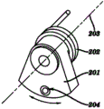
Embodiments of the invention are automatic starting devices, inertia-activated mechanism for example, and this inertia-activated mechanism is in operation during the CENTRIFUGAL ACCELERATING and during CENTRIFUGAL ACCELERATING, start; This automatic starting device comprises housing 209; This housing is accommodated swing arm 201, torsion spring 202, non-movable axis 203, is positioned at the breech lock 204 on the swing arm 201 and is installed in the movable starter 206 on the housing 209, and wherein swing arm 201 is rotatably connected with torsion spring 202 and is rotatably connected with non-movable axis 203 on being installed in housing 209, wherein when at CENTRIFUGAL ACCELERATING and the centrifugal force that changed between deceleration period; Swing arm can be around axle swing pivotally; Wherein during CENTRIFUGAL ACCELERATING, swing arm 201 is away from the rotation pivot compression torsion spring 202 of axle 203, wherein between centrifugal deceleration period; Discharge compression energy from torsion spring 202 and make swing arm 201 rotations; Wherein breech lock 204 is retractable, during CENTRIFUGAL ACCELERATING, bounce back, and when obtaining maximum centrifugal speed and during maximum centrifugal speed, stretch out; Wherein movable starter 206 is arranged in juxtaposition with swing arm 201 and between deceleration period, contacts with the breech lock 204 of swing arm; Breech lock 204 is in the state of stretching out after maximum centrifugal speed and between deceleration period, wherein through between deceleration period, contacting with the breech lock that stretches out 204, the recoil swing/rotation of arm 201 is moved movable starter 206.
The movable starter 206 that is positioned on the inertia-activated mechanism can for example be pullled motion or ahead running with linear movement mode mobile valve.Selectively, the movable starter 206 that is positioned on the inertia-activated mechanism can move with rotary movement.Movable starter 106 can be the valve starter, for example the piston valve starter.The valve starter comprises compression spring or torsion spring.
Automatic starting device one embodiment comprises the piston valve starter; This piston valve starter comprises head 205, lightweight compression spring 207 and piston 208; Wherein head 205 is connected with piston 208; Wherein lightweight compression spring 207 surrounds piston 208, and wherein head 205 is arranged in juxtaposition with swing arm 201.
Another embodiment of automatic inertia starting drive comprises: the movable starter 213 in top swing arm 201, bottom swing arm 212, upper movable starter 206 and bottom; Wherein each swing arm all has the breech lock 204 that can bounce back; One of them swing arm contacts a movable starter with breech lock, wherein each swing arm and corresponding movable starter stacked arrangement vertically.
An embodiment of automatic inertia starting drive has two swing arms and two corresponding movable starters, comprises movable breech lock block 211, and wherein breech lock block 211 contacts with the movable starter 213 in bottom.
An embodiment of automatic inertia starting drive has two swing arms and two corresponding movable starters; Comprise breech lock block release member 210; Wherein an end of breech lock block release member 210 contacts with upper movable starter 206; The other end contacts with breech lock block 211, and wherein the startup of upper movable starter 206 breaks away from the movable starter 213 in breech lock block 211 and bottom.
Description of drawings
Figure 1A-Fig. 1 E illustrates the stereogram of disposable separator/inspissator device.Figure 1A illustrates the embodiment of the valve operation between position 1, position 2 and position 3 that utilizes linear movement, so that utilization comprises the valve of groove collection container material is transferred to lower chamber from upper chamber.Figure 1B illustrates the embodiment of the valve operation between position 1, position 2 and position 3 that utilizes rotating mechanism, in valve, material is transferred to lower chamber from upper chamber so that utilization comprises the valve of space collection container.Fig. 1 C illustrates the embodiment of the valve operation between position 1, position 2 and position 3 that utilizes changeover valve and linear movement combination, so that utilization comprises the valve of rotatable groove collection container material is transferred to lower chamber from upper chamber.Fig. 1 D is the stereogram of an embodiment of separator/inspissator device; This separator/inspissator device comprises two chambers (top chamber 101 and bottom chamber 103) and is positioned at a valve 111 of passage 113, is used for before centrifugal action, separating, concentrating and the collection particulate from fluid sample.Fig. 1 E be when valve 111 in moderating process or after centrifugal circulation in passage 113 along shown in direction when moving, the separator shown in Fig. 1 D/stereogram of inspissator device after centrifugal action.
Fig. 2 A-Fig. 2 C illustrates the use of another embodiment of separator/inspissator device; This separator/inspissator device comprises three chambers (first chamber 101, second chamber 103 and the 3rd chamber 105) and at first valve 111 between first chamber and second chamber and second valve 112 between second chamber and the 3rd chamber, is used for separating, concentrating and collect particulate from fluid sample.
Fig. 3 is two stereograms that the embodiment of the separator/inspissator device that comprises three chambers 101,103 shown in Figure 2 and 105 is shown.
Fig. 4 A-Fig. 4 E illustrates the stereogram of the embodiment of disposable separator/inspissator device.Fig. 4 A is another prototype figure of separator/inspissator.Fig. 4 A illustrates the separator/inspissator that has half manually-operated gate starter, and this half manually-operated gate starter is the cam sleeve starting drive 400 (also shown in Figure 26) that is used for operated valve.Fig. 4 B illustrates the cross-sectional view of Fig. 4 A.Fig. 4 C illustrates first valve 111 and second valve 112 that is positioned at position 1.Fig. 4 D illustrates first valve 111 that is positioned at position 2, thereby the fluid that allows to be collected in the valve collection container is transferred to second chamber 103 from first chamber 101.Fig. 4 E illustrates second valve 112 that is positioned at position 2, thereby the fluid that allows to be collected in the valve collection container is transferred to the 3rd chamber 105 from second chamber 103.
Fig. 5 is the stereogram of an embodiment that is designed to shift from top chamber the metering valve of fixed volume.Shown is measuring tank or the chamber that is used for from the upper chamber to the lower chamber, distributing predetermined solid volume.
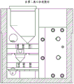
Fig. 6 A-Fig. 6 B is the sectional drawing of an embodiment of valve system, and the valve that connects top chamber and middle part chamber is shown.Fig. 6 A illustrates the metering valve that is positioned at initial position, to collect sample in the first or second centrifugal cycle period from upper chamber.Fig. 6 B illustrates the metering valve that is positioned at the final position, with subsequently or second centrifugal cycle period allow sample to get into lower chamber.In Fig. 5, show the metering valve of this embodiment separately.In this embodiment, the distance between the chamber is 0.400 inch.
Fig. 7 A-Fig. 7 B illustrates the design of an embodiment of separator/inspissator device.Fig. 7 A illustrates the sectional drawing of separator/inspissator device.Fig. 7 B illustrates the said three-dimensional body shell figure of separator/inspissator device.The composite design of this embodiment three continuously than capacitor and two valve systems.
Fig. 8 is the sketch map that three parts that downcut from the design of Fig. 7 are shown.These parts can be foundry goods for example molded or processing, and the fastener hole shown in perhaps can passing through securing member keeps together.
Fig. 9 A-Fig. 9 B is the sketch map of an embodiment of separator/inspissator device.Fig. 9 A illustrates the transparent view of front portion of an embodiment of separator/inspissator device.Fig. 9 B illustrates the three-dimensional transparent stereogram of watching from the drift angle of an embodiment of separator/inspissator device.Should be noted that the stereogram and the prototype figure of separator/inspissator device that this embodiment has been shown in Fig. 3.
Figure 10 A-Figure 10 E illustrates the embodiment of the inertia-activated mechanism that the valve of the separator/inspissator device that is used to make Fig. 1 moves and the sketch map of the various motions implemented by this device that is connected with movable starter.This starting drive comprises rotatablely moving of swing arm 201.Figure 10 A is the stereogram of the embodiment of starting drive, and this starting drive comprises the swing arm 201 that is connected with torsion spring 202, be positioned at the bounced back breech lock 204 on the swing arm 201 of rotation 203 rotations.Figure 10 B is the stereogram of the starting drive of Figure 10 A, wherein when swing arm along shown in direction when recoil breech lock 204 contacts and push movable starter 206.Figure 10 C is the stereogram of the embodiment of the starting drive shown in Figure 10 A, and this starting drive comprises the movable starter that is used to rotatablely move.Figure 10 D is the stereogram of an embodiment of the starting drive shown in Figure 10 A, and this starting drive comprises and is used for the movable starter that linearity is pullled motion.Figure 10 E is the stereogram of an embodiment of the starting drive shown in Figure 10 A, and this starting drive comprises the movable starter that is used for the linear advancement motion.
Figure 11 A-Figure 11 F illustrates the use of the embodiment shown in Figure 10 E, and wherein movable starter is carried out the linear advancement motion.Figure 11 A is the stereogram of the embodiment shown in Figure 10 E when starting drive remained static before the beginning centrifugal action.Figure 11 B and Figure 11 C are that the embodiment shown in Figure 10 E is at the stereogram when the breech lock 204 of starting drive is withdrawn during the CENTRIFUGAL ACCELERATING.Figure 11 D is the stereogram of the embodiment shown in Figure 10 E under the maximum centrifugal speed that breech lock 204 stretches out.Figure 11 E and Figure 11 F be the embodiment shown in Figure 10 E between centrifugal deceleration period at breech lock 204 seized pistons 208 and the stereogram when making piston stretch out (propelling).
Figure 12 A-Figure 12 B is the stereogram of an embodiment of inertia starter.Figure 12 A illustrates swing arm, and wherein the torsion spring (not shown) is connected with the top fixed wall with swing arm.Figure 12 A illustrates swing arm in the position in centrifugal circulation accelerating period, and wherein (for example, in the time of 3000G), swing arm is swung away from valve when big gravity reaches certain level.Figure 12 B illustrates swing arm in the position between centrifugal circulation deceleration period, and wherein when gravity reached certain less gravity level (for example, less than about 1500G), swing arm was swung towards the valve of separator/inspissator device.In the embodiment shown in Figure 12 A and Figure 12 B, inertia-activated mechanism is designed to start the valve that has piston.In the actuator piston that is used to push valve shown in Figure 12 B.
Figure 13 is the string diagram of the stereogram of separator/inspissator device 319 shown in Figure 2, and this separator/inspissator device construction becomes the automatic separative element 318 that is operably connected and makes up to form with the inertia-activated mechanism that comprises piston valve starter 317.
Figure 14 A-Figure 14 C illustrates the stereogram and the prototype figure of an embodiment of the automatic separative element 318 of combination, comprises separator/concentrator unit 319 and is connected with automatic starting device shown in Figure 13 317.Figure 14 A illustrates the three-dimensional transparent stereogram of separator/inspissator device 319; The piston valve starter 317 (for example, the automatic inertia starting drive 317) that this separator/inspissator device construction becomes the valve in separator/inspissator device can be activated device starts.Figure 14 B is the two-dimentional vertical view of the separator shown in Figure 14 A/inspissator device 319; Separator/inspissator device 319 that piston valve starter 317 (for example, the automatic inertia starting drive 317) that the valve that is configured in separator/inspissator device can be activated device starts is shown.Figure 14 C illustrates the view of an embodiment of separator/inspissator device 319; This separator/inspissator device construction becomes the valve in separator/inspissator device to be started by movable starter 206 (not shown) of automatic starting device (for example, the automatic inertia starting drive 317).
Figure 15 is the stereogram of an embodiment of automatic starting device, and this automatic starting device comprises two swing arms 201 and 212 and two movable starters 206 and 213, is used in to start like Figure 13 and valve shown in Figure 14.
Figure 16 A-Figure 16 E illustrates the use of embodiment shown in Figure 15.Figure 16 A and Figure 16 B are stereograms embodiment illustrated in fig. 15, be illustrated in first centrifugal action during the breech lock block prevent that second breech lock from stretching out.Figure 16 C is a stereogram embodiment illustrated in fig. 15, is illustrated between the first centrifugal deceleration period breech lock block release member 210 breech lock block 211 is moved backward.Figure 16 D is a stereogram embodiment illustrated in fig. 15, is illustrated in stretching out of second breech lock during the second centrifugal action maximum speed.Figure 16 E is a stereogram embodiment illustrated in fig. 15, is illustrated in that second breech lock blocks second bottom piston and second bottom piston is stretched out between the second centrifugal deceleration period.
Figure 17 A-Figure 17 D is illustrated in two continuous centrifugal cycle periods and uses the connection embodiment of two automatic inertia starting drives shown in Figure 15 A to be enabled in the two-shipper tool valve in the automatic separating apparatus 319 of combination shown in Figure 13 continuously.Figure 17 A is a stereogram embodiment illustrated in fig. 13, is illustrated in start unit and separative element during first CENTRIFUGAL ACCELERATING.Figure 17 B is a stereogram embodiment illustrated in fig. 13, and first valve that is illustrated between first deceleration period starts.Figure 17 C is a stereogram embodiment illustrated in fig. 13, and the process of second CENTRIFUGAL ACCELERATING is shown.Figure 17 D is a stereogram embodiment illustrated in fig. 13, and second valve that is illustrated between second deceleration period starts and final valve location.
Figure 18 A-Figure 18 B be illustrated in quicken and between deceleration period as the chart of the torsion spring constant of angle function.Figure 18 A illustrates the function of torsion spring constant and accelerating period angle, and Figure 18 B illustrates the torsion spring constant and the function of angle between deceleration period.
Figure 19 is the block diagram that illustrates from the repeatability of the metered volume of a valve prototype.Form with block diagram presents the volume by the metering of 5 μ l valves according to 60 tests.Average final volume is 13.04 μ l.
Figure 20 illustrates in the water 1 * 10
3The clump count of cfu/ml is as the block diagram of centrifugation time function.Being recovered as~10,000 bacterium colonies of expectation, thus overall recovery in this embodiment is lower than 1%, but can be reached the bigger rate of recovery by those skilled in the art's optimization.Show the error line of a standard deviation.
Figure 21 is the block diagram that bacterium recovery percentage for Pluronic (addition polymers of polypropylene glycol and oxirane (polyethers)) device coating or uncoated is shown.Show the error line of a standard deviation.
Figure 22 is that to illustrate for serum sample and blood and the lysate sample that is 1: 1 for ratio from concentration be 1 * 10
2Cfu/ml and 1 * 10
3The block diagram of the bacterium output of cfu/ml E.coli (Escherichia coli).Show the error line of a standard deviation.
Figure 23 is the block diagram of the repeatability of metered volume.Form with block diagram presents the volume by the metering of double valve prototype according to 10 tests.Average output volume is 9.8 μ l, confirm when valve from the position 1 transfer to the material of another chamber from a chamber when operating position 2 volume have reliable consistent volume.
Figure 24 illustrates for 1 * 10
2The serum that cfu/ml infects and the blood of equal portions and lysate sample are from the block diagram of the repeatability of the metered volume of double valve prototype and 5 μ l valve prototypes.Show the error line of a standard deviation.
Figure 25 is for the SERS spectrum (top trace) of contrast E.coli sample acquisition with for being mixed with about 1 * 10
9The SERS spectrum (bottom recording curve) that the water sample of cfu/ml E.coli obtains from original prototype output.The shape of these two spectrum is very similar.
Figure 26 is the 3 dimensional drawing of an embodiment of half manually-operated gate starter (as cam sleeve starting drive 400).Figure 26 illustrates the cam sleeve starting drive of two valves that are used to start separator/inspissator device, and wherein cam sleeve starting drive 400 has second cam 410 (cam 2) that is configured to operate top first cam 401 (cam 1) of first valve in separator/inspissator device and is configured to operate second valve in separator/inspissator device.In addition, also show and the stop teat 402,403,405 of first cam 401 in same one side, be used for the operation of by-pass valve control and the rotation that cam sleeve centers on passage.
Figure 27 A-Figure 27 B illustrates the sketch map of first and second valves 111 by the operation from the primary importance to the second place in separator/inspissator device of the cam sleeve device 400 shown in the embodiment of Figure 26.Figure 27 A illustrates the position of first and second valves 111 in first and second passages of separator/inspissator device, and wherein the orientation of cam sleeve starting drive during first centrifugal action allows first valve and second valve to be positioned at position 1.After the first centrifugal circulation, cam sleeve starting drive 400 is along rotation counterclockwise, thereby first cam 401 makes first valve 111 move to the position 2 shown in Figure 27 B.Figure 27 B illustrates first cam 401 and has connected and start first valve 111; Make it 1 move to position 2 from the position; Wherein first cam has made valve move away from first cam 401 along the axis of first passage, and the bottom valve also is not activated (the bottom valve is held in place and puts 1).When valve 111 contact stop teats 405, this cam sleeve starting drive can not be rotated in a clockwise direction, therefore can only be along rotation counterclockwise.In addition, with before preventing that the cam sleeve starter further is rotated counterclockwise, this cam sleeve starting drive can only be along counterclockwise rotating certain distance at first valve, 111 contact stop teats 402.In this structure, carry out the second centrifugal circulation.After the second centrifugal circulation, cam sleeve starting drive 400 is rotated in a clockwise direction, and makes bottom (for example, second) valve move to the position 2 shown in Figure 27 C from the position 1 shown in Figure 27 B.Figure 27 C illustrates second cam 410 and has connected and start second valve 111, and it is slided away from second cam 410 along second channel, and wherein first valve does not move.When first valve, 111 contact stop teats 402, therefore this cam sleeve starting drive can not can only be rotated in a clockwise direction along rotation counterclockwise.In addition, with before preventing that the cam sleeve starter from further turning clockwise, this cam sleeve starting drive can only be rotated in a clockwise direction certain distance at first valve, 111 contact stop teats 403.Carry out the 3rd centrifugal circulation at this structure (for example, first and second valves all are arranged in position 2).
Figure 28 is illustrated in and uses auto-starter to start the embodiment of valve in the special centrifugal machine.Separator/inspissator 319 is arranged in the machine basket or the retainer 502 of the rotor of special centrifugal machine 500; Auto-starter 501 is connected with the bottom of special centrifugal machine; Wherein auto-starter 501 comprises the external arm (not shown), and this external arm is configured to be operably connected to start the valve of separator/inspissator.After each centrifugal circulation, the centrifuge follow procedure stops separator/inspissator 319 is remained on the machine basket of appropriate location, makes the external arm of auto-starter in isolation/concentration is handled, can start suitable valve.In certain embodiments, special centrifugal machine can comprise one or more auto-starters 501.
Figure 29 illustrates the 3 dimensional drawing of embodiment of the auto-starter 501 of special centrifugal machine shown in Figure 28.Here the auto-starter of specific embodiment has two cylinders as the mechanical device of two external arm of operation, and wherein two external arm are configured to be operably connected with the valve of separator/inspissator device.In the embodiment shown, the external arm that is operably connected with first valve is positioned at the position that starts first valve.
Figure 30 illustrates the two-dimentional vertical view of the embodiment of auto-starter shown in Figure 29 501.
Specific embodiment
Embodiments of the invention relate to particle separation, specifically, relate to from fluid sample and to concentrate and the device of separating particles (for example, bacterium or pollutant).Use separator/inspissator device (for example, disposable separator/inspissator device) to realize the isolation/concentration of the particle in the sample through continuous centrifugation step.
In certain embodiments, separator/inspissator device is used for extracting and concentrated granular from fluid sample, for example; From biological specimen (for example; Blood or other biological sample) the middle extraction and concentrated bacterium or particle, particle wherein concentrated or that separate can be used for follow-up analysis, for example; The clinical diagnosis in downstream and detection, for example PCR, bioMEMS device etc.
In one embodiment; The present invention relates to a kind of disposable particle enrichment facility (this paper is called " separator/inspissator " device); Wherein in a plurality of centrifugation step, carry out particle separation, wherein sample is delivered to another chamber from a chamber in disposable apparatus in the continuous centrifugal step process.Each chamber connects via the passage that comprises valve, and controls sample flowing from a chamber to another chamber through the valve that is positioned at the passage that connects each chamber.As disclosed herein, valve can be operated through any way in the multitude of different ways, for example, and manual, half manual, semi-automatic or automatic operation.
In certain embodiments; Separator/inspissator device; Disposable separator/inspissator device for example; Comprise: (a) at least one first chamber and at least one second chamber, wherein first chamber has upper entrance that is used for the inlet flow sample body and the lower part outlet that is used for fluid is outputed to valve that is positioned at first cavity bottom; Second chamber has the upper entrance and the bottom output that is positioned at cavity bottom that is used for receiving from valve fluid; (b) first passage, first passage connect the output of first chamber and the input of second chamber; (c) be housed in the first interior valve of first passage, wherein first valve comprises collection container and control material flowing from first chamber to second chamber.In certain embodiments, valve is the metering valve that comprises collection container.In optional embodiment, said device can comprise any amount of further chambers, for example, the 3rd chamber or multi-cavity chamber more, wherein each chamber vertical array and each the chamber utilization passage of accommodating valve is connected with adjacent chamber.
In certain embodiments, shown in Figure 1A, valve can for example manually, partly manually or automatically be operated into one of three diverse locations.For example, when valve was operated into primary importance (for example, position 1), the collection container in the valve was collected sample from first passage.When valve was operated into the second place (for example, position 2), the collection container in the valve will deposit to second chamber from any sample that first passage is collected.Randomly and in certain embodiments, before being operated into primary importance, valve (for example can be operated into the 3rd position; Position 3), in the 3rd position, the valve collection container seals first chamber; Thereby prevent that sample collection is in collection container; Therefore when sample was carried out centrifugal action, particulate collecting prepared to get into the valve collection container at the output of first chamber when valve is operated into position 2.
Therefore, in certain embodiments, the method that material is transferred to second chamber from first chamber requires 3-valve operation method to come operated valve separator/inspissator device, and this method comprises:
Step 1: carry out valve is moved to first valve operation of position 3, wherein valve is oriented to the outlet sealing of the collection container of valve to first chamber, flow to second chamber to prevent material from first chamber.
Step 2: fluid sample that will be to be separated is added to the inlet of first chamber and carries out the first centrifugal circulation.The valve that is positioned at position 3 stops the outlet flow valve collection container of material from first chamber, thus make first centrifugal cycle period material be collected in the bottom of first chamber.
Step 3: carry out valve is moved to second valve operation of position 1, wherein the outlet that the outlet of first chamber is opened wide and aimed at first chamber of the collection container in the valve, and carry out the second centrifugal circulation.The valve that is arranged in position 1 make second centrifugal cycle period material be collected in the collection container of valve.
Step 4: carry out valve is moved to the 3rd valve operation of position 2, wherein the collection container in the valve opens wide and aims at the inlet of second chamber to the inlet of second chamber, and carries out the 3rd centrifugal circulation.The valve that is positioned at position 2 make the 3rd centrifugal cycle period material transfer to second chamber from the collection container of valve.
In certain embodiments, the method that material is transferred to second chamber from first chamber comprises that more effective 2-valve operation method comes operated valve separator/inspissator device, and this method comprises,
Step 1: fluid sample that will be to be separated is added to the inlet of first chamber.
Step 2: carry out valve is moved to first valve operation of position 1, wherein the collection container in the valve is aimed at the outlet of first chamber, and carries out the first centrifugal circulation.The valve that is arranged in position 1 make first centrifugal cycle period material be collected in the collection container of valve.
Step 3: carry out valve is moved to second valve operation of position 2, wherein the collection container in the valve is aimed at the inlet of second chamber, and carries out the second centrifugal circulation.The valve that is positioned at position 2 make second centrifugal cycle period material transfer to second chamber from the collection container of valve.This from the position 1 to the position 2 valve operation process can repeat the valve of any amount of separation upper chamber and lower chamber, transfer to lower chamber to allow sample from upper chamber.
In certain embodiments, can operated valve, make valve move to 1 linear movement position 2 from the position, for example through pullling motion (for example, seeing Figure 1A) or ahead running along passage.In certain embodiments, valve can be constructed with and be connected with passage so that spiral screw rod shape mechanism that can operated valve, makes the rotation of valve will make valve 1 move to position 2 along linear direction from the position.In other embodiments, can be through rotatablely moving operated valve, so that valve 1 rotates to position 2 from the position, for example see Figure 1B.
As disclosed herein, can through any manually, half manually or auto-starter come operated valve.
In certain embodiments, the operated valve of can manually (for example, using hand), wherein known by one of skill in the art any device pushes or pulls out valve.In one embodiment, use the hand operated valve, and not by the starting drive that can be operatively connected.In one embodiment, use the hand operated valve, and not by the bar that leads in the passage separately.In this embodiment, after centrifugal action stops, can be with hand operated valve manually.
In another embodiment, can be partly operated valve manually, for example use cam sleeve starting drive disclosed herein.In these embodiment, can use the cam sleeve device that is connected with operated valve with disposable separator/inspissator to come operated valve, the cam sleeve device that wherein assembles through for example transversal passage of manual rotation and valve axis comes operated valve.In other embodiments, can use other half manual start devices to come operated valve, for example, allow to use to well known to a person skilled in the art that lipstick formula starting drive comes the sleeve of operated valve.In certain embodiments, after centrifugal action stops, can using cam sleeve starting drive or other half manual start devices to come the manual operation valve.Because the manual operation of the valve operating device (for example, cam sleeve starting drive disclosed herein) that the valve operation requirement is connected, so be called " half manually " valve operation among this valve operation this paper.
In another embodiment, can use inertia-activated mechanism for example disclosed herein operated valve automatically, wherein between centrifugal deceleration period, carry out valve operation.Between deceleration period, inertia-activated mechanism presses against piston on the valve, thus the valve in the operating walk way.In certain embodiments, inertia-activated mechanism can cooperate with the rotor or the machine basket that use in the commercially available centrifuge, and perhaps in optional embodiment, inertia-activated mechanism can be assembled in the special centrifugal machine.
In optional embodiment, use the mechanical external arm operated valve automatically be arranged in special or special centrifugal machine, wherein, centrifuge carries out valve operation (for example, seeing Figure 28) after stopping fully.In certain embodiments; The external arm of the valve in the operation special centrifugal machine can be any mechanism that is used for operated valve; For example; Said mechanism includes but not limited to motor, solenoid, pump, mechanical pump, lever, cylinder starting drive disclosed herein, and wherein when centrifugal circulation stopped, the external arm contact was also operated at least one valve at least one disposable separator/inspissator device in the centrifuge.In this embodiment; At least one separator/inspissator device is arranged in the special centrifugal machine; Make the external arm parts of the starting drive that connects centrifuge (for example, as) of operated valve after each centrifugal circulation, can cooperate and operated valve with separator/inspissator device.In these embodiment, come automatically to carry out valve operation through the mechanism that external arm is moved with the contact valve.In certain embodiments; For example after centrifugal circulation, stop and being positioned in centrifuge that the external arm that makes mechanically operated starting drive can cooperate and during the position of operated valve when separator/inspissator device; For example after centrifugal action, automatically carry out valve operation.For example, in having the 3-chamber device of two valves, each valve can sequentially move, and for example, first valve 1 moves to position 2 from the position after accomplishing centrifugal circulation, and second valve 1 moves to position 2 from the position after follow-up centrifugal action then.
Should be appreciated that to the invention is not restricted to concrete grammar as herein described, scheme and reagent etc., and can change.The term that this paper uses only is used to describe the purpose of specific embodiment, rather than is used for limiting scope of the present invention, and scope of the present invention only is defined by the claims.
The definition of term
Except as otherwise noted, all technology of this paper use are all identical with the common implication of understanding of those skilled in the art in the invention with scientific terminology.
The term " fluid sample " that this paper uses is meant any aqueous solution; For example water, Chi Shui, non-mobile water are (for example; In clinical or laboratory installation; Like incubator), the cell suspending liquid in body fluid (for example, urine, whole blood, serum, celiolymph) and liquid cell culture or the culture medium.
The term " particulate " that this paper uses is meant solid particle, the insoluble matter that floats on a liquid.For example, be suspended in haemocyte or bacterium in the blood.In the pool water within, particulate comprises bacterium and other microorganisms, dust and rotten vegetation.The particulate that also is called as particulate matter (PM) or fine particle is the small branch of the solid that floats on a liquid.In certain embodiments, particulate is the bacterium with Any shape (for example, spherical (for example, coccus) or shaft-like (for example, bacillus)) and size or form.It is eukaryotic 1/10th that the bacterial cell general size is about, and length is about the 0.5-5.0 micron usually.In certain embodiments, particulate is the ultra micro bacterium, that is, than the bacterium of little a lot, the about 0.3-0.2 micron of diameter of normal bacteria cell, for example, the diameter of in seawater, finding is less than the coccus of 0.3 μ m.In certain embodiments, particulate is nanometer bacteria (also being called as " calcification nano particle "), and they are that diameter is the Living Organism of 0.1 μ m.In certain embodiments, particulate is L shaped bacterium (also being called as L type bacterium, L type variant or cell membrane defective (CWD) bacterium), and they are the bacterial isolateses that do not have cell membrane.L shaped can in the laboratory, the generation from the various bacteria kind (for example, hay bacillus or Escherichia coli) that has cell membrane usually.
In other embodiments, particulate can be any pathogen, for example virus, Mycophyta, algae (for example, unicellular alga), bacterium etc.As the particulate of virus, can be any virus that length is generally the 20-300 nanometer.Pathogen virus for example includes but not limited to the virus of following kind: adenovirus, picornavirus, herpesviral, have a liking for hepatovirus, flavivirus, retrovirus, orthomyxovirus, paramyxovirus, newborn polyomavirus, polyomavirus, baculoviral, togavirus.Some significant pathogen viruses produce: smallpox, influenza, mumps, measles, varicella, Ebola hemorrhagic fever and rubella.As the particulate of bacterium, can be any bacterium that is generally the 1-5 micron.The pathogen bacterium for example includes but not limited to such as pathogen bacteriums such as Mycobacterium tuberculosis, streptococcus and pseudomonad, Shigella, campylobacter and salmonellas.The pathogen bacterium also produces such as infectious diseases such as lockjaw, typhoid fever, diphtheria, syphilis and leprosys.As the particulate of fungi, can be any bacterium that length is generally the 1-40 micron.Fungal pathogens comprises the microorganism of Eucaryotae, and they are saprophage but can cause the mankind, animal and plant disease normally.Fungi is the most common cause of disease of crops and other plant disease.Fungi as the cause of disease that skin, nail or yeast infect, is the common issue with among the immunocompetence crowd.
The relevant term " material " of the material with transferring to another chamber from a chamber that this paper uses is meant the mixture or the composition of particle and insoluble matter (for example, organelle, cell membrane etc.) and small number of samples fluid.The size of transferring to the particle in the material of next chamber depends on the duration and the speed of centrifugal circulation.For example, depend on centrifugal circulation, material can comprise the mixture that contains particle (for example, bacterial cell) and small volume of fluid supernatant.In other words, " material " is from the particulate of the fluid sample composition with a small amount of supernatant, wherein supernatant account for material cumulative volume (v/w) preferably less than 1%, or less than 2%; Or less than about 5%, or less than about 10%, or less than about 20%; Or less than about 30%, or less than about 50%, or less than about 60%; Or less than about 70%, or less than about 80%, or less than about 90%.In certain embodiments, material contain account for material cumulative volume (w/v) at least about 1%, or at least about 10%, or at least about 20%; Or at least about 30%, or at least about 40%, or at least about 50%; Or at least about 60%, or at least about 70%, or at least about 80%; Or at least about 90%, or at least about 95%, or at least about the particulate of 98% amount.In certain embodiments, the amount of particulate is any integer between about 1-100% that accounts for the material cumulative volume.In certain embodiments, particulate accounts for the 90-99% of material volume.
The term " valve " relevant with described separator/inspissator device that this paper uses is meant sealing in the passage of each chamber of jockey, the valve that stops and move.Flowing of the chamber of the chamber of the mobile control material of valve in passage above the valve below the valve.
The relevant term " physical separation " of the chamber with in separator/inspissator device that this paper uses be meant each chamber not direct neighbor be connected to each other.
The term relevant with separator/inspissator device with the valve starter that this paper uses " can be operatively connected " and be meant valve starter physical connection and towards separator, makes that to allow the valve starter approaching and start the valve in separator/inspissator device.
Term " special use " centrifuge that this paper uses is meant the centrifuge of the customization that is used to specially to use with disposable apparatus disclosed herein, and wherein this special centrifugal machine comprises that automatic starting device is to operate the valve in separator/inspissator device between each cycle of rotation.
The term " starting drive " that this paper uses is meant the device that moves valve as herein described.
" arm " relevant with inertia-activated mechanism that this paper uses is meant and is utilized in the swing arm of power after centrifugal deceleration, to move that produces during the centrifugal action.Swing arm during the acceleration of centrifugal action (for example, speed increases) from the valve of separator/inspissator device along rightabout rotation/swing (seeing Figure 11).In other words, because the centrifugal force during centrifugal action, swing arm moves along rightabout from the center of revolving force
The term relevant with centrifuge " centrifugal circulation " that this paper uses is meant that centrifuge reaches the acceleration that fixing predetermined gravity is provided with, and makes the centrifugal force setting keep the predetermined set time, and centrifuge slows down when the set time finishes then, to the last stops.
Except in example of operation or referring else, all numerals that are expressed as component or reaction condition that this paper uses are to be understood that to modifying with term " about " in all cases.When relevant with percentage, term " about " can represent ± 5%.
Only if refer else clearly in the literary composition, singular references " " and " being somebody's turn to do " comprise the implication of plural number.Similarly be, only if refer else clearly in the literary composition, word " or " be used for comprising " with ".Though with method described herein and material type like or the method and the material that are equal to can be used for enforcement of the present invention and test, appropriate method and material are described below.Term " comprises " and is meant " comprising ".Abbreviation " e.g. (for example) " comes from Latin language and this paper is used to represent non-limitative example.Therefore, abbreviation " e.g. (for example) " and term " for example (for example) " synonym.
The term that this paper uses " comprises " and being meant except the qualification key element that exists, and can also have other key elements.Use " comprising " to represent to be included rather than limit.
Separator/inspissator device-General Principle
Embodiments of the invention relate to and use centrifugal action from fluid sample, to separate and separator/inspissator device, piece-rate system and the method for concentrated particulate.
One aspect of the present invention relates to a kind of separator/inspissator device, as comprises the disposable separator/inspissator device of at least two chambers (for example, first chamber and second chamber), and the fluid of wherein controlling between each chamber through valve flows.As disclosed herein, can carry out valve operation through any way, for example, perhaps operate through automatic through manual operation, half manual operation.When valve in the passage of separator/inspissator device when primary importance is operated the second place, valve allows the fluid sample of designated volume to be delivered to another chamber from a chamber.The fluid volume of transferring to next chamber from a chamber can comprise particulate matter; For example following particulate matter: the bead of any solid particulate matter of being paid close attention to (for example; Such as haemocyte, bacterial cell, the isocellular bead of blood platelet), water pollutant (for example, pond water deposit) etc.Figure 1A-Fig. 1 C, Fig. 2 and Fig. 4 illustrate mobile valve to collect the consecutive steps of concentrated particulate matter.
Referring now to Fig. 1 D, Fig. 1 E and Fig. 2; In one embodiment; The present invention provides a kind of and from fluid sample, separates and the separator/inspissator device of concentrated particulate through centrifugal action; Comprise: (a) vertically disposed at least two chambers, first chamber 101 and second lower chamber 103, wherein first chamber 101 has the ingate that is used to apply sample; Wherein first chamber 101 is connected through first passage 113 with second chamber 103, and first passage comprises the valve 111 of control from the fluid sample transfer of first chamber, 101 to second chambers 103; Valve 111 formation that wherein are housed in the first passage prevent that any material from flowing to the tight seal of second chamber from first chamber.First valve 111 from the position 1 to the position 2 mobile permission 103 fluid shifts from first passage 101 to second channel.In certain embodiments, valve 111 is to be designed to particulate and fluid with predetermined are assigned to second chamber from first chamber metering valve.Figure 1A-Fig. 1 E illustrates the embodiment of the separator/inspissator device with two chambers.
In one embodiment, for example, shown in Fig. 2 A-Fig. 2 B, separator/inspissator device also comprises the 3rd chamber.In certain embodiments; The 3rd chamber is positioned at the below of second chamber 103; Wherein the outlet of second chamber 103 is connected through second channel 114 with the inlet of the 3rd chamber 105, and second channel comprises second valve 112 of control from the fluid sample transfer of second chamber, 103 to the 3rd chambers 105; Second valve, 112 formation that wherein are housed in the second channel prevent that any material from flowing to the tight seal of the 3rd chamber from second chamber.Second valve 112 from the position 1 to the position 2 mobile permission shift from the fluid of second chamber, 103 to the 3rd chambers 105.In certain embodiments, second valve 112 is to be designed to particulate and fluid with predetermined are assigned to the 3rd chamber from second chamber metering valve.In certain embodiments; Like what this paper discussed; First chamber can contain buffer solution before adding fluid sample, for example, wherein the buffer solution in first chamber is for example to be used for preferentially making such as lysis such as haemocyte keeping the complete lysis buffer of bacterial cell simultaneously.In certain embodiments, lysis buffer contains the Tween-20 of low percentage.In certain embodiments, second chamber or the 3rd chamber contain the reception fluid, for example washing or flush fluid.
For example, comprise among some embodiment of three chambers that the particle matter that intermediate cavity can be used to allow to get into intermediate cavity is by " washing " or " flushing " at separator.In one embodiment, second chamber also contains cleaning solution (like water, salt solution) or buffer solution known in the art.
In certain embodiments, separator/inspissator device can comprise any amount of chamber, for example; At least 2; Or at least 3, or at least 4, or at least 5; Or at least 6 or more a plurality of chambers, these chambers can be configured to via the fluid connection each other of at least one valve between each chamber.In certain embodiments, second, third, the 4th, the 5th chamber etc. is positioned at any position with any order, and in certain embodiments, second, third, the 4th, the 5th chamber etc. all is set together.In these embodiment, the outlet of top chamber is connected with the inlet of below chamber through the passage that comprises valve, wherein from the position 1 to the position 2 valve operation control fluid from the transfer of the chamber that is positioned at the lower chamber top.
For instance; Separator/inspissator the device that comprises four chambers has first chamber and second chamber that is connected with first valve through first passage; Second chamber and the 3rd chamber that are connected with second valve through second channel; The 3rd chamber and the 4th chamber that are connected with the 3rd valve through third channel; Wherein first valve, 12 valve operation control fluid transfer, second valve from the position from first chamber to second chamber to the position from the position 1 to the position 2 valve operation control fluid from the transfer of second chamber to the, three chambers, and the 3rd valve from the position 1 to the position 2 valve operation control fluid from the transfer of the 3rd chamber to the four chambers.
In certain embodiments, the chamber of lower position is as collection chamber, and the collection sample that concentrates with access can take off from device in this collection chamber.For example, comprise among the embodiment of 2 chambers that second chamber 103 is as collection chamber at separator/inspissator.Comprise that at separator/inspissator among other embodiment of 3 or 4 chambers, the 3rd chamber 105 or the 4th chamber are used separately as collection chamber.In certain embodiments, as the below chamber of collection chamber, for example second, third or the 4th chamber (or any other below chamber) are slides.Fig. 4 C illustrates the embodiment that the 3rd chamber 105 wherein plays the effect of slide collection chamber, and wherein slide collection chamber can take off and directly in the microscopically analysis.In certain embodiments, separator/inspissator device only comprises first chamber and first valve, and can be configured to connect to receive fluid from first chamber with collection chamber's (for example, second chamber).
In certain embodiments, below chamber (for example, second chamber in the 2-chamber device or the 3rd chamber in the 3-chamber device etc.) can be used as collection chamber, and collects concentrated sample.This collection chamber has the input that is used to receive sample usually, but is not used in the output that sample flows out.In certain embodiments, collection chamber can be configured to any collection chamber, for example; Any collecting pipe (for example; 0.2ml pipe or 0.5ml pipe or 1.5ml pipe or 2.0ml pipe) or be used to collect the collection chamber of any geometrical construction that concentrates sample, for example, collection chamber has the slide of collecting the indenture of sample from the outlet of first passage; For example, microslide.In certain embodiments, as second chamber of collection chamber or below chamber (for example, the the 3rd of the multi-cavity chamber device the, the 4th, the 5th chamber etc.) can after collecting sample, take off from separator/inspissator device.In certain embodiments, collection chamber separates with device and can be connected on separator/inspissator device.Only comprise among some embodiment of first chamber and first valve at for example device; Device can be configured to collection chamber is connected the bottom of 1-chamber-1-valving; Make collection chamber to receive sample, and wherein control the fluid that gets into collection chamber and shift through the operation of first valve from the output of first chamber.
In certain embodiments, each chamber stacked arrangement vertically.In certain embodiments, top (for example, the top) outlet of chamber and the inlet of lower chamber are directly vertically located, and for example comprise as the indenture of collection container or the embodiment in space (for example, seeing Figure 1B) at the valve that is arranged in the passage that each chamber is separated.In optional embodiment; The outlet of top chamber and the inlet of lower chamber are vertically located; But at a distance of small distance very, for example comprise embodiment (for example, Figure 1A, Fig. 1 D, Fig. 1 E and Fig. 2) as the measuring tank of collection container at the valve that is arranged in the passage that each chamber is separated along passage.
Disposable separator/inspissator device
Fig. 4 illustrates an embodiment of the disposable separator/inspissator device of the single use that is used in the centrifuge (for example, oscillating machine basket centrifuge).In certain embodiments, disposable separator/inspissator device shown in Figure 4 can be used in about 10 minutes from the middle separation of bacterial of biological specimen (for example, the whole blood sample of 100ml).In certain embodiments, the disposable apparatus shown in Fig. 4 A comprises at least one metering valve, and has collection chamber's (for example, the 3rd chamber), directly from sample, extracts particulate with the bottom from disposable apparatus.
In certain embodiments, disposable apparatus is used in the method for separation of bacterial from blood.For example; Use device shown in Figure 4; This method comprises blood is added to first chamber that contains lysis buffer; For example, wherein the preferential cracking haemocyte of lysis buffer keeps any bacterial cell complete simultaneously, is positioned under the situation of position 3 at first valve then device is carried out centrifugal action to produce the bacterium bead.In this embodiment, the volume ratio of concentration, lysis buffer and the blood through changing lysis buffer and the related time chemical reaction of optimizing the blood cracking.First valve can be operated to position 1 to collect a part of of balling-up bacterium and device is carried out centrifugal action.First valve 111 is operated to the next valve operation of position 2 a part of supernatant is transferred to second chamber from first chamber, and wherein sample is diluted.Repeat this process, for example, wherein device rotate, valve operation (from the position 3 to the position 1 valve operation 2), rotation, valve operation (from the position 1 to the position 2 valve operation 2), so that a part of supernatant is transferred to the 3rd chamber from second chamber.
In certain embodiments, valve is a metering valve.Fig. 4 A illustrates the embodiment of the outside of disposable separator/inspissator device, and Fig. 4 B and Fig. 4 C are illustrated in the cross-sectional view of embodiment of disposable separator/inspissator device of the first centrifugal cycle period.In certain embodiments, the sample container in first chamber 101 can hold at least about 100ml fluid sample (for example, blood sample) and at least about the buffer solution (for example, the lysis buffer in the top chamber) of 10-95ml.In certain embodiments, first chamber 101 is sealed by removable lid.In the bottom of first chamber, sample container forms funnel and down to the collection container in the metering valve (for example, 10 μ l metering valves).In case it is spherical that any bacterium in blood cracking and the blood has formed in metering valve, then operation (for example, manually, partly manually or automatically) valve, and 10 μ l samples in the metering valve are transferred to second chamber (for example, dilution chamber).Fig. 4 D is illustrated in the embodiment that first valve (bottom valve) 111 is operated to position 2 disposable separator/inspissator afterwards.Second chamber 103 (for example, cut-back tank) can contain diluted fluid (for example, the water of 900 μ l or other dilution buffer liquid), is 1: 100 so that sample is diluted, thereby the lysis buffer that shifts is diluted about 99%.
It is spherical that any bacterium of having transferred to second chamber 103 (for example, cut-back tank) utilizes second centrifugal action in second metering valve, to form again.First and second valves that Fig. 4 E illustrates 3-chamber disposable separator/inspissator are positioned at the embodiment of position 2 after the operation of second valve.In certain embodiments, when second (or bottom) valve operation to position 2, the sample of 5 μ l is transferred to the 3rd chamber 105 (for example, collection chamber or transfer vessel) from second chamber, the user can reclaim concentrated sample then.
In embodiment as herein described; First chamber 101 also is designed in the porch at top wideer, being easy to fluid input, and forms hopper outlet (seeing Fig. 7-9) in the bottom of chamber; This outlet is connected to first passage, and first passage is connected to the inlet of second chamber.Thereby, can change the size and dimension of chamber and passage, with type, volume and the size of the type of fluid that meets the needs of separation, the particle that will collect and required collected volume.In one embodiment, bottom chamber (for example, the 3rd chamber 105 in the 3-chamber device) is less than first chamber 101.In one embodiment, bottom chamber (for example, the 3rd chamber 105 in the 3-chamber device) can contain cleaning solution or the suspension that is useful on collection pellet shapes particle.
In an embodiment of separator as herein described/inspissator device, fluid sample is a blood sample.In other embodiments, fluid sample can be any biological specimen, for example water or body fluid (like urine, aspirate or celiolymph (CSF)), blood plasma, sperm etc.In other embodiments, fluid is such as (for example, Chi Shui or beverage or other water samples) samples such as water samples, and can be used for impurity and the pollutant of for example checking that fluid sample exists.
In certain embodiments, separator as herein described/inspissator device contains first and/or second solution in arbitrary chamber, for example, and lysis buffer in first chamber or surfactant solution.In certain embodiments, lysis buffer can be used for the cracking haemocyte but not cracking bacterial cell when fluid sample is blood sample.In one embodiment, lysis buffer is 0.005%Tween 20 solution.In one embodiment, lysis buffer is 0.8%Na
2CO
3/ 0.05%TRITON X-100 solution.In one embodiment, the lysis buffer in the top chamber is 1: 1 with the ratio of blood sample.In other embodiments, lysis buffer is 1: 2,1: 3,1: 4,1: 5,1: 9 or 1: 20 with the ratio of fluid sample.In certain embodiments, the concentration of Tween 20 is 0.005%.
In one embodiment, the chamber of separator/inspissator device is coated with 0.5g/L Pluronic or 1%BSA or any other coating, sticks on the wall of separator to prevent particulate matter.Depend on the employed material of wall of separator and fluid and the particulate matter that needs separate, possibly require or not require the coating of wall.Those skilled in the art can utilize easily-testing program as herein described to confirm this point.
In one embodiment, first chamber 101 of separator/inspissator device contains lysis buffer.In one embodiment, lysis buffer cracking haemocyte or other cells or microorganism.
In one embodiment; The diluted fluid that second chamber 103 of separator/inspissator device contains certain volume (for example; Water or be used to wash the cleaning solution of particulate matter); For example comprise under the situation of three chambers that for example second chamber can contain at least about 1000 μ l or less than the volume of 1000 μ l at device.
In one embodiment, comprise at device under the situation of three chambers that first chamber 101 of separator/inspissator device contains lysis buffer, second chamber 103 of separator contains the buffer solution (for example, water) of certain volume.
In certain embodiments; Separator/inspissator device can be configured to by any suitable material; Include but not limited to polymeric material, for example polyacetals, polyurethane, polyester, polytetrafluoroethylene (PTFE), polyethylene, polymethyl methacrylate, polymethylacrylic acid hydroxy methacrylate, polyvinyl alcohol, polypropylene, acetal copolymer, PEEK, PEVA, esters of acrylic acid, Merlon, polymethylpentene, polyether-ketone, polyphenylene oxide, polyvinyl chloride, Merlon, polysulfones, acrylonitrile-butadiene-styrene (ABS) PEI, polyvinylidene fluoride and copolymer and composition.Other preferable material comprise polysiloxanes, fluoridize polysiloxanes, ethylene-propylene rubber, fluoroelastomer and composition thereof.Other preferable material comprise PLA, polyglycolic acid, polycaprolactone, gather P-Dioxane ketone, poly (propylene carbonate) and copolymer thereof.
In one embodiment, separator/inspissator device for example is configured to integrated device through injection moulding or additive method known in the art.In other embodiments, separator is become by several parts or unit architecture, as the separator of being processed by modular unit.For example; Each modular unit all can comprise the chamber with entrance and exit; Its middle outlet is connected with the passage that can accommodate valve, and wherein this chamber has the outlet that is connected with the inlet of another chamber, and another chamber is the chamber that is close in next modular unit.In these embodiment, any amount of modular unit (for example, 3 of 3-chamber device as herein described modular units) can be assembled together.In certain embodiments, each unit can fit together (seeing Fig. 3, Fig. 7-9 and embodiment part) through the whole bag of tricks known in the art.
Injection moulding is a kind of possibility method of making the disposable separator of one.Optional method is that shown in Fig. 3-9, the several sections of structure separator fits together them then.In certain embodiments, shown in Fig. 9 B, but 3-chamber separator can use three processing parts manufacturings, but these three processing parts can tighten together through any fixing means, for example, the device each bight use a plurality of screws or buckle.In certain embodiments; For the 3-chamber device; As shown in Figure 8; But processing parts can be constructed as follows: but (i) the first top processing component 115 comprises the first of first chamber 101, first passage 113 and second chamber 103, but but (ii) processing component 116 can comprise second chamber 103 remainder, second channel and the 3rd chamber 105 first and (iii) bottom processing component 117 comprise the remainder of the 3rd chamber 105.Yet, the present invention includes any method of making disposable apparatus.Following Fig. 7-8 illustrates the sketch map of three parts.In certain embodiments; Three parts can be configured to fit together to form security seal; Wherein first process part 115 substructure become with second process part 116 the top be fixedly connected, and second process part 116 substructure one-tenth be fixedly connected with the top that part 117 is processed in the bottom.In certain embodiments, processing parts can cooperate as the staggered overlap joint shown in Fig. 4 B or slide together.In certain embodiments; Processing parts 115,116,117 utilizes binding agent, sealant or viscose glue to remain on the appropriate location; And in other embodiments, process parts 115,116,117 and can utilize encapsulating material (for example, centering on the plastics of whole device) to keep together.
In certain embodiments, for example, shown in Fig. 9 B, process parts 115,116,117 and use securing member 118 (for example, screw) to keep together regularly, wherein each is processed part and all has been constructed with the space that securing member is used.In certain embodiments; Using securing member (for example, screw) will process under the situation that parts 115,116,117 are fixed together, the bottom is processed parts 117 and is comprised that screw immerses oneself in through hole; Middle section 116 has screwing through hole, screws the district and top component 115 has screw.In certain embodiments, the lid that parts 115 are configured to comprise top chamber 101 usefulness is processed at the top, in case fluid sample accident is overflowed.Fig. 3 and Fig. 9 illustrate the separator of the 3-spare formula device that finally is assembled into.
In one embodiment, separator/inspissator device is the device that single uses, and refers to this device and only uses once, abandons then.In another embodiment, separator is nonexpondable device, wherein after using the first time of separating the first fluid sample; Can wash and clean this device; And in certain embodiments,, carry out sterilization and reuse in order to carry out second and subsequently fluid sample separation.
The operation of separator/inspissator device
Separator/inspissator device is designed to utilize centrifugal action.For example, when using the fluid isolation/concentration of 2-chamber device, before the centrifugal circulation of beginning, first valve 111 is positioned at position 3 or position 1 in passage 113, so that tight seal and prevention are from any leakage of first chamber, 101 to second chambers 103.If first valve 111 is positioned at primary importance, then shown in Fig. 6 A, fluid flow to the collection container (for example, measuring tank) of first valve 111 from top chamber 111.Can realize tight seal spare by the rubber "O that is positioned on the valve.During centrifugal action, the particle matter in first (for example, top) chamber 101 will be deposited in the outlet at bottom (Figure 1A) of infundibulate first chamber and get into the collection container (for example, measuring tank) of first valve 111.The collection container that has accumulated in the bottom of first chamber and when the first centrifugal circulation finishes, accumulated in first valve 111 at particle matter (for example; Measuring tank) after in; Shown in Figure 1B and Fig. 6 B; First valve 111 moves to the second place (position 2) in passage 113 operation allows material to flow to the inlet of second chamber 103 from the valve collection container (for example, from measuring tank) of first valve 111.The second centrifugal circulation makes particle matter move to second chamber 103 from the valve collection container (for example, from measuring tank) of first valve, and moves to the outlet at bottom of second chamber.
In the embodiment of 3-chamber separator/inspissator device; Like Fig. 2 and shown in Figure 4; Will have two valves (promptly; First valve 111 and second valve 112) and corresponding first passage 113 be positioned at the first passage 113 that connects first chamber 101 and second chamber 103 with second channel 114, the first valves 111, and second valve 112 is positioned at the second channel 114 of connection second chamber 103 and the 3rd chamber 105.
Before any centrifugal circulation of beginning; First valve 111 and second valve 112 are located in its corresponding passage 113 and 114 and are on the thronely put 1 or position 3, so that with respect to valve and corresponding passage tight seal and stop any leakage from the chamber of valve top to the chamber of valve below.In certain embodiments, first valve 111 is positioned to the outlet that the valve collection container is aimed at first chamber 101, thereby allows material from first chamber, the 101 unimpeded valve collection containers (for example, measuring tank) that flow to valve.After first centrifugal action, operate first valve 111 to move to position 2, make the valve collection container aim at the inlet of second chamber 103, thereby allow valve collection container (for example, measuring tank) unimpeded flow to second chamber 103 of material from valve.Begin the second centrifugal circulation; Wherein (for example from the valve collection container of first valve 111; Measuring tank) particle matter is deposited to second chamber 103 and is deposited in the outlet at bottom of second chamber; And wherein second valve 112 moves to primary importance, and particle matter gets into the valve collection container of second valve 112.After the second centrifugal circulation; Operate second valve 112 (for example to move to the second place; Position 2); Make the valve collection container aim at the inlet of the 3rd chamber 105, thereby allow material to flow to the 3rd chamber 105 so that final collect (Fig. 2 and Fig. 4) from the valve collection container of second valve 112 is unimpeded.
As disclosed herein, separator/inspissator device (for example, disposable separator/inspissator device) can make up with the actuating mechanism that is used for operated valve.Exemplary starting drive disclosed herein (for example comprises half manual start device; The cam sleeve starting drive) and automatic starting device (for example; Inertia-activated mechanism); Yet these starting drives are not only the starting drive of the valve that can be configured to start disposable separator/inspissator device extremely.Usually, starting drive provides following mechanism: with correct operation in tandem valve, thereby prevent the maloperation owing to the disposable separator/inspissator that causes with the wrong sequence operated valve.
In certain embodiments, in the oscillating machine basket of fixed angle or special centrifugal machine, carry out the centrifugal action of separator/inspissator device.In one embodiment, in the commercially available centrifuge of standard, carry out centrifugal action.In another embodiment, in clinical centrifuge, carry out centrifugal action.Clinical centrifuge is known in the art and is used for the analysis of blood, other body fluid and environmental samples.
Be to be general operation process below like the embodiment of Fig. 3, Fig. 4, Fig. 9, Figure 13 and 3-chamber 2-valve separator/inspissator device shown in Figure 14 for separator/inspissator device.
A. all surface is thoroughly cleaned in the back before use.Cleaning can known by one of skill in the art any method be carried out, and for example comprises being cleaned by manufacturer, perhaps passes through such as any sterilizing cleaning such as steam, autoclave, radiosterilization system.In certain embodiments, can carry out number of assembling steps 1-11 by manufacturer.
B. assembling:
1. O shape ring is placed in the groove of cavity bottom part 117, and the cavity bottom part is accommodated the 3rd chamber 105 (final collection chamber) (seeing Fig. 8 and Fig. 9).
2. if desired, water is filled the 3rd chamber 105.
3. middle parts 116 are arranged and are placed on the bottom parts 117, the top of the 3rd chamber 105 is aimed in the output of parts 116 in making.
4. O shape ring is placed in the groove of the chamber that centers on middle parts 116.
5. if desired, water is filled middle part chamber 103.If the volume required chamber that overflows then can carry out the filling of water after assembling.
6. if desired, filter is placed on the O shape ring top on the chamber 103 of middle part.
7. on the parts 116, make the output of top part 115 aim at the top of second chamber 103 in top part 115 being arranged and is placed on.
8. be fixedly connected top part 115, middle parts 116 and bottom parts 117.Insert four 1-3/4 " 1/4 "-20 screw rods.Evenly tighten.Avoid threading off because of damaged screw in centrifugal cycle period.In some cases, it is enough using two screw rods.
9. three O shape rings are installed on each valve 111 and 112.Guarantee not distortion.
10. the beveled end of valve 111 and 112 is at first inserted the side near the top chamber delivery outlet carefully.Insert before flushing with the outside of prototype in the end of exposing always.
11. if desired, fill second chamber 102 through angled side ports.
12. fill first chamber 101 with sample.
13. cover first chamber 101 with lid.Randomly, the belt lid downwards.
In 1/2 gram, offset balance 14. guarantee relative machine basket.
Dismounting
1. take off separator/inspissator from centrifuge, keep vertically carefully simultaneously.Be placed on then on the firm horizontal surface.
2., then using to have 1 if the water level in second chamber 103 is positioned at O shape ring top " syringe of pin reduces water level through angled port.
3. dismantle down each and process parts 115,116,117 through unscrewing all screw rods.
4. remove the liquid in first chamber 101 and second chamber 103 rightly.
5. use plastic tweezer or other plastic tools from valve, to take out O shape ring.
Cleaning
1. after relating to biological test, remove all O shape rings at every turn.
2. clean all inner surfaces and outer surface.
If a. use blood, then use 10% bleaching agent, water flushing then.
If b. only use bacterium, then on all parts, use 70% ethanol.
3. paper towel and compressed air finish-drying.
The use of disposable separator/inspissator device
In certain embodiments, disposable separator/inspissator device is as the Dispoable medical device, and this Dispoable medical device can be from biological specimen (for example, from blood or such as other biological samples such as liquid physiology samples; Urine, CSF etc.) in quickly and efficiently (~10 minutes) extract particle (for example, bacterium), and it concentrated being used for analyze.Because this is disposable closed system, pollutes sample and/or make the operator be exposed to potential harmful pathogen and the risk of bacterium so also reduced.In addition, because this process does not need the technical staff to add any buffer solution or the sample except treating the concentrated biological sample, thus reduced human error, and the user of minimum training also can operate this process.In addition, in piece-rate system, use this disposable separator/inspissator device can simplify the moving process of the reform through forced labor that concentrates sample, and do not need accurate pipetting.This separator/inspissator device combines to keep the liquid sealing, shift accurate amount liquid and can be manually or partly manually or use the starting drive disclosed herein valve of operation fast and safely automatically with hand.
In certain embodiments, separator/inspissator device directly extracts the balling-up material from the sample bottom, and can not upset remaining non-spherical sample or supernatant.
In one embodiment, separator/inspissator device is the device that single uses, and refers to this device and only uses once, abandons then.In another embodiment, separator is nonexpondable device, wherein after using the first time of separating the first fluid sample, can wash and clean this device, supplies second/different fluids sample to reuse then.
In certain embodiments; Disposable separator/inspissator device is used for being concentrated in the sample that follow-up downstream diagnosis is used; And the sample that concentrates can be used in the following method: the particle that concentrates in the sample is useful, for example, comes the bacterium of autoblood or other fluids; Thereby can be used in the subsequent analysis, for example PCR, bioMEMS device etc.
In certain embodiments; Disposable separator/inspissator device is used for particle or cell separation; So that the particle of separation different size from body fluid (for example, blood platelet and such as other blood products such as red blood cell and blood plasma), for example; Special cell type is like neutrophil cell or stem cell or particle.In certain embodiments, disposable separator/inspissator device is used for concentrating the particle of body fluid, for example, and enrichment in blood platelet and the composition that in neutrophil cell, lacks.
In certain embodiments, disposable separator/inspissator device can be used for concentrating and extract pollutant or sediment from the solution of any kind.In certain embodiments, for example, depend on the cell type that in being loaded into the fluid sample of top chamber, is asked to cracking, can preloaded first chamber 101, make it contain different lysis buffers.In certain embodiments, second chamber 103 can the different buffer solution of preloaded, and for example cleaning solution can be used for the spherical sample that washing obtains from first (top) chamber 101.In addition, disposable separator/inspissator device can comprise that treating before the top chamber that is loaded into separator/inspissator device concentrates the filter of removing big solid the fluid sample.These filters can be reticular filters or allow cell to pass but prevent other filters well known in the art that maxicell aggregation or fibr tissue pass.
In certain embodiments, disposable separator/inspissator device is disposable fully.In other embodiments, several parts of separator/inspissator device are disposable, and other parts are reusable.For example, in certain embodiments, the chamber and the housing of separator/inspissator device are disposable, and valve (for example, metering valve) is reusable.Use between different separator/inspissator devices each, can known by one of skill in the art any way be sterilized by reusable metering valve.In addition, this paper also comprises the reusable form of separator/inspissator device, comprises reusable chamber and the housing and the valve (for example, metering valve) of separator/inspissator device.
The valve of separator/inspissator device
As disclosed herein, control sample separator/inspissator device flowing through the valve that is arranged in passage from a chamber to another chamber, wherein passage is between each chamber and connect each chamber.As disclosed herein, valve can be operated through in the multitude of different ways any, for example, and manually, partly manually or operation automatically.
Can be with such as pullling or linear movement mode operated valve such as ahead running.For example, in certain embodiments, can operated valve make valve 1 move to position 2 with the linear movement mode from the position, for example pull motion (for example, seeing Figure 1A) or ahead running along passage.Selectively; Can use screw rod etc. rotatablely move with linear movement mode operated valve; For example, valve can be configured with and channel attached spiral screw rod shape mechanism, and the rotation that makes valve can be operating as valve can make valve 1 move to position 2 along rectilinear direction from the position.In other embodiments, for example see Figure 1B, can through make valve from the position 1 rotate to position 2 rotatablely move operated valve.As disclosed herein, can through any manually, half manually or auto-starter come operated valve.Have among some embodiment of at least two valves at separator/inspissator; Each valve can be configured to through different mechanism's operations; For example; Can be through on rectilinear direction, valve 1 being moved to position 2 and operate first valve 111 (seeing Figure 1A) from the position along passage 113, can be through 1 rotating to rotatablely moving of position 2 and operate second valve 112 (seeing Figure 1B) from the position.In these embodiment, the inlet of second chamber 103 departs from the outlet of first chamber 101 usually, and the outlet of inlet substantial registration second chamber 103 of the 3rd chamber 105.
As disclosed herein, can through any manually, half manually or auto-starter come operated valve.Have among some embodiment of at least two valves at separator/inspissator, for example, can carry out the valve operation of each valve through different operation mechanism, for example, can manual operation first valve 111, and operate second valve 112 automatically.Therefore, as disclosed herein, can use any combination of distinct methods to operate a plurality of valves of separator/inspissator device.Usually, in certain embodiments,, for example operate the whole valves in separator/inspissator device through manual, half manual or automatic method of operating through identical method.
In certain embodiments, can manually (for example, use hand) and come operated valve, wherein known by one of skill in the art any way pushes or pulls out valve.In one embodiment, do not coming operated valve with hand under the situation by the starting drive that can be operatively connected.In one embodiment, by or do not come operated valve with hand under the situation by the bar that leads to the valve in the passage separately.In this embodiment, can be after centrifugal action stops with hand operated valve manually.
In one embodiment, the valve in operation separator/inspissator device gets into second chamber (for example, the chamber of valve below) with the fluid that allows designated volume from a chamber (for example, the chamber of valve top).The designated volume that is shifted is by the decision of the volume of valve collection container, and depends on type, volume, quality and the size of particle to be collected and required collected volume, and the designated volume that is shifted can be any volume.For example, the volume of valve collection container can be received and rise to 10 milliliters for 10.In certain embodiments, the volume of valve collection container and thereby the volume that between each chamber, shifts can be at least 10 receiving and rise to 10 milliliters approximately.If the use metering valve for example has the valve of measuring tank collection container or metering space collection container, wherein collection container allows to shift at least more than the 10nl; For example, about 5 μ l, or about 10 μ l; Or about 100 μ l, or about 1ml, or about 2ml; Or 2ml to 10ml, or any integer between the 10nl to 10ml, then can confirm the volume that between each chamber, shifts in advance.
In certain embodiments, valve is a metering valve.In an embodiment of separator as herein described/inspissator device; Valve is a metering valve; For example wherein valve is constructed with the collection container of collecting the specific volume of certain volume sample from the outlet of upper chamber; Operated valve is assigned in the inlet that receives chamber (for example, second chamber) with the specific predetermined that will be collected in the collection container then.In certain embodiments, the valve collection container is collected 10 μ l from the outlet of a chamber, then 10 μ l is assigned in the inlet of another chamber.This metering valve with collection container allows the sedimentation particulate matter of predetermined to get into the inlet of second chamber (for example, the chamber of valve below) from the outlet of a chamber (for example, the chamber of valve top).Metering valve is to have the sample that allows predetermined is delivered to the collection container (for example, space (seeing Figure 1B) or groove (seeing Figure 1A or Fig. 5)) of next chamber from a chamber valve.In certain embodiments, the valve collection container has any required volume, for example any volume, and for example 10nl to 100 μ l or 100 μ l to 1ml, in certain embodiments; Valve collection container (for example, groove) allows to shift at least about 5 μ l, and perhaps in certain embodiments, groove allows will be at least about 5 μ l; Or at least about 6 μ l, or at least about 7 μ l, or at least about 8 μ l, or at least about 9 μ l; Or at least about 10 μ l, or at least about 15 μ l, or at least about 20 μ l, or at least about 30 μ l; Or, or at least about 50 μ l, or at least about 100 μ l, or transfer to next passage greater than the fluid volume to be transferred of 100 μ l at least about 40 μ l.
Have among some embodiment of at least two valves at separator/inspissator, the collection container in the different valves can have different volumes.For example; In the separator/inspissator with three chambers, first valve 111 can have the collection container of volume for about 10nl to 10ml (for example, about 1000 μ l); Second valve 112 can have the collection container of volume for about 10nl to 10ml (for example, about 10 μ l).In certain embodiments, the valve collection container has any volume size, for example any volume between the 10nl to 10ml.In other embodiments, the valve collection container has the volume of 5 μ l to 10ml.Fig. 5 shows the embodiment of the valve collection container of metering valve.Those skilled in the art can construct to have and be used for required predetermined is assigned to second or the valve of the valve collection container of any required geometry of the inlet of back chamber.
Fig. 5 and Fig. 6 illustrate have as the groove of valve collection container and be designed in the passage of separator/inspissator device from the position 1 move to the metering valve of position 2 embodiment.Metering valve can design and be arranged to tight seal and under accelerating period and target gravity, stop any leakage from the upper chamber to the lower chamber.Tight seal can be realized the "O of for example being processed by rubber through the "O on the valve.
Metering valve can be processed by any material, for example, can be the disposable material of plastics, artificial or other devices.In certain embodiments, metering valve is disposable movable device.In certain embodiments, metering valve is reusable movable device, can between the use of method and disposable separator/inspissator device, sterilize to metering valve by known by one of skill in the art any way.In certain embodiments; Valve can be configured to by any suitable material well known by persons skilled in the art; Include but not limited to polymeric material, for example polyacetals, polyurethane, polyester, polytetrafluoroethylene (PTFE), polyethylene, polymethyl methacrylate, polyacrylic acid hydroxy methacrylate, polyvinyl alcohol, polypropylene, acetal copolymer, PEEK, PEVA, esters of acrylic acid, Merlon, polymethylpentene, polyether-ketone, polyphenylene oxide, polyvinyl chloride, Merlon, polysulfones, acrylonitrile-butadiene-styrene (ABS) PEI, polyvinylidene fluoride and copolymer and composition.Other preferable material comprise polysiloxanes, fluoridize polysiloxanes, ethylene-propylene rubber, fluoroelastomer and composition thereof.Other preferable material comprise PLA, polyglycolic acid, polycaprolactone, gather P-Dioxane ketone, poly (propylene carbonate) and copolymer thereof.
Manually booting of valve
In certain embodiments, after each centrifugal circulation, manually carry out valve operation, and maybe can not be operatively connected any optional equipment on separator/inspissator device by physics.In these embodiment, come mobile valve with hand.
In certain embodiments, can use bar to arrive the valve in passage and the thrust unit passage.In certain embodiments, manually accomplish promotion with hand.Bar has been represented the equipment of the non-physical connection that is used for mobile valve.In certain embodiments, can use bar in the passage of separator/inspissator device, manually to pull valve, for example, wherein have on the valve with bar on the cover hook that is connected of cover hook, thereby can use bar to pull valve.In certain embodiments, bar is disposable.In certain embodiments, bar and valve are reusable.
In an embodiment of 2-chamber separator/inspissator device, when centrifuge stops,, the first centrifugal circulation pushes first valve 111 after finishing.In an embodiment of 3-chamber separator/inspissator device, after each the centrifugal circulation in two continuous centrifugal circulations, sequentially operate two valves 111 and 112.After centrifuge when the first centrifugal circulation finishes stops, manual operation first valve 111.Then, carry out the second centrifugal circulation, and when the second centrifugal circulation is tied, promote second valve 112.
In certain embodiments, can be at the valve of manual operation separator/inspissator device after each centrifugal circulation.In certain embodiments, under not by the situation of the equipment that is connected with device, manually carry out valve operation.
Be the exemplary step of the manually-operated gate operation of separator/inspissator device (Fig. 1) of after each centrifugal circulation, having two chambers below.The manual operation of valve must not relate to the equipment that is connected with device physical, for example starting drive.
Step 1: before any centrifugal circulation of beginning, first valve 111 is positioned at position 1 or position 3 in passage 113, with tight seal and stop any leakage from first chamber, 101 to second chambers 103.If valve is positioned at position 1, then the valve collection container is aimed at the outlet of first chamber 101, to allow from first chamber, the 101 unimpeded collection containers (for example, measuring tank) that flow to first valve.
Step 2: wait to separate and/or concentrated fluid sample to first chamber, 101 loadings.Cover the top of this chamber, to avoid overflowing during centrifugal action.
Step 3: separator/inspissator device is placed in the centrifuge.Begin the first centrifugal circulation and continue 5 minutes with 3000rcf, thus in first chamber 101 the sedimentation particulate matter, particulate matter will and be deposited in the collection container (for example, measuring tank) of first valve 111 towards the outlet sedimentation of first cavity bottom.
Step 4: when the first centrifugal circulation finishes; After centrifuge stops; Take off separator/inspissator device from centrifuge, and manually first valve 111 is operated the second place in the passage, make the valve collection container aim at the inlet of second chamber 103; Thereby shown in Figure 1B and Fig. 6 B, allow to flow to the unimpeded of second chamber 103 from the measuring tank of valve.Can use bar to arrive the valve in the passage.
Step 5: separator/inspissator device is put back in the centrifuge.Begin the second centrifugal circulation and continue 5 minutes with 3000rcf, so that the collection container (for example, measuring tank) of particle matter from first valve 111 moved to the inlet of second chamber 103 and arrive the bottom of this chamber so that collect.
Step 6: when the second centrifugal circulation finishes, after centrifuge stops, taking off separator/inspissator device from centrifuge, get into second chamber 103 and collect sedimentation/sample that concentrates.
Be after each centrifugal circulation, to utilize manually booting of valve to operate to have the exemplary step of the separator/inspissator device of three chambers below.In certain embodiments, each valve is moved and not by the equipment that is connected with device.
In the embodiment of 3-chamber separator/inspissator device; Like Fig. 2 and shown in Figure 4; Have two valves 111 and 112 and corresponding passage 113 and 114; First valve 111 is positioned at the first passage 113 that connects first chamber 101 and second chamber 103, and second valve 112 is positioned at the second channel 114 that connects second chamber 103 and the 3rd chamber 105.
Step 1: before any centrifugal circulation of beginning, two valves 111 all are positioned at passage with 112, so that with respect to valve and corresponding passage tight seal and any leakage of the chamber below stoping from the chamber of valve top to valve.Simultaneously, each valve all can be positioned at primary importance (position 1), thereby allows from the unimpeded measuring tank that flow to valve of chamber of valve top.
Step 2: wait to separate and/or concentrated fluid sample to top chamber 101 loadings.Cover the top of this chamber, to avoid overflowing during centrifugal action.
Step 3: separator/inspissator device is placed in the centrifuge.Begin the first centrifugal circulation and continue 5 minutes with 3000rcf, thus in first chamber 101 the sedimentation particulate matter, particulate matter will and be deposited in the collection container (for example, measuring tank) of first valve 111 towards the outlet sedimentation of first cavity bottom.
Step 4: when the first centrifugal circulation finishes; After centrifuge stops, taking off separator/inspissator device from centrifuge, and the collection container that carries out the manual operation that first valve 111 is shifted the second place (position 2) onto is made the valve 111 of winning (for example; Measuring tank) inlet of aligning second chamber 103; Thereby shown in Fig. 2 B and Fig. 4 D, allow to flow to the unimpeded of second chamber 103 from the collection container (for example, measuring tank) of first valve.Can use bar to arrive the valve in the passage.
Step 5: separator/inspissator device is put back in the centrifuge.Begin the second centrifugal circulation and continue 5 minutes with 3000rcf; So that from the collection container of first valve 111 (for example with particle matter; Measuring tank) moves to the inlet of second chamber 103; And be positioned under the situation of position 1 at second valve 112, move in the collection container (for example, measuring tank) of second valve 112.
Step 6: after the second centrifugal circulation and after centrifuge stops; Take off separator/inspissator device from centrifuge, and carry out with the manual operation that second valve 112 is shifted the second place (for example, the position 2) onto make second valve 112 collection container (for example; Measuring tank) inlet of aligning the 3rd chamber 105; Thereby shown in Fig. 2 B and Fig. 4 D, allow to flow to the unimpeded of the 3rd chamber 105 from the collection container (for example, measuring tank) of second valve.Can use bar to arrive the valve in the passage.
Step 7: separator/inspissator device is put back in the centrifuge.Begin the 3rd centrifugal circulation and continue 5 minutes with 3000rcf, so that the collection container (for example, measuring tank) of particle matter from second valve 112 moved to the inlet of the 3rd chamber 105 and arrive the bottom of this chamber so that collect.
Step 8: when the 3rd centrifugal circulation finishes, after centrifuge stops, taking off separator/inspissator device from centrifuge, get into the 3rd chamber 105 and collect sedimentation/sample that concentrates.
In certain embodiments, under situation by the equipment that is connected with device, the valve of manual operation separator/inspissator device after each centrifugal circulation.For example, starting drive can be according to the sequencing operated valve, wherein starting drive can physics with operationally be connected with separator as herein described/inspissator device.In certain embodiments, manually (that is, using hand) starts the starting drive that is used for operated valve, and wherein valve operating device is the cam sleeve starting drive.
Partly manually booting of valve
In other embodiments, can after each centrifugal circulation, manually carry out valve operation by starting drive.Because need the user with the mobile-initiated device of hand to start the valve in separator/inspissator device, be called as " partly manually booting " so this valve starts.In certain embodiments, utilize the valve operation of starting drive to need manual operation, that is, use hand operated.This starting drive can be configured to can be operatively connected with separator/inspissator device.
In optional embodiment, can use any half manual start device to operate the valve in separator/inspissator device, for example, allow the sleeve of operated valve or well known to a person skilled in the art lipstick formula starting drive.In one embodiment, the cam sleeve starting drive that use can be operatively connected carries out valve operation, perhaps after centrifugal action stops, manually booting other half manual start devices with hand.In certain embodiments; Can use half manual start device to carry out valve operation; This half manual start device comprises the bar with scroll or spiral slot and is configured to be installed in the passage with complementary scroll or spirality indenture, thereby moves and operate the valve in separator/inspissator device through the bar of manually screwing in the chamber.
In certain embodiments, for example can use cam sleeve starting drive 400 half disclosed herein starter gate valve door operation manually.Figure 26 illustrates an embodiment of this cam sleeve device.In certain embodiments, can use cam sleeve device 400 to start valve, this cam sleeve device and disposable separator/inspissator can be operatively connected, and start valve thereby utilize the manual rotation of cam sleeve starting drive or screw action.
In certain embodiments, cam sleeve starting drive 400 is the rotating rings around the valve part, and this cam sleeve starting drive uses inner cam to start metering valve, inwardly to promote 0.1 inch on valve from its original position.The combination that cam sleeve starting drive 400 has driving cam 401,410 and is used as the guiding teat 402,403,405 of excessive rotation brake spare.Allow the user only along permission direction rotating cam ring like this, thereby at first eliminated any possibility that starts wrong valve.
Referring to Figure 26; Show an embodiment of half manually-operated gate starter; This half manually-operated gate starter is to be suitable for starting first valve 111 of separator/inspissator device and the cam sleeve starting drive 400 of second valve 112, and wherein cam sleeve starting drive 400 has first cam 401 (cam 1) that is configured to start first valve 111 in separator/inspissator device and second cam 410 (cam 2) that is configured to start second valve 112 in separator/inspissator device.Cam sleeve starting drive 400 also comprises stop teat 402,403,405; The stop teat be configured to top jaw with the one side in; So that the direction of rotation and the rotary distance of control cam sleeve starting drive, thereby start the valve in separator/inspissator device.
In the embodiment of 3-chamber separator/inspissator device; As shown in Figure 4; Cam sleeve starting drive 400 is configured to make first valve 111 and second valve 112 moving in the corresponding passage separately; First valve 111 is positioned at the first passage 113 that connects first chamber 101 and second chamber 103, and second valve 112 is positioned at the second channel 114 that connects second chamber 103 and the 3rd chamber 105.
Cam sleeve starting drive 400 can surround separator/inspissator device, and in certain embodiments, is not connected with device physical, but still is configured to when operate at least one valve during along suitable direction rotating cam sleeve starting drive with hand.
In certain embodiments, cam sleeve starting drive 400 is configured in 2-chamber separator/inspissator device, sequentially move two valves 111 and 112.For example; This cam sleeve starting drive surrounds second chamber 103 and the 3rd chamber 105; Make cam (for example, first cam 401 and second cam 410) aim at first valve 111 and second valve 112 in the passage 114 with the passage 113 of separator/inspissator device.For example; First cam 401 is aimed at and can contacted and be operatively connected first passage 113 interior first valve, 111, the second cams 410 of first chamber 101 and second chamber 103 and aims at second valve 112 in the second channel 114 that connects second chambers 103 and the 3rd chamber 105.
Be after each centrifugal circulation, to operate the exemplary step of the valve of separator/inspissator device (Fig. 1) below with two chambers through rotating cam sleeve starting drive 400 shown in figure 26.
Step 1: shown in figure 27, cam sleeve starting drive 400 be positioned at a part of separator/inspissator device around, make it be orientated first valve 111 and be positioned at the primary importance that is fit to the first centrifugal circulation.For example, collection container aim at first chamber outlet to collect the bead in the metering valve.
Step 2: wait to separate and/or concentrated fluid sample to first chamber, 101 loadings.Cover the top of this chamber, to avoid overflowing during centrifugal action.
Step 3: separator/inspissator device is placed in the centrifuge.Begin the first centrifugal circulation and continue 5 minutes with 3000rcf, thus in first chamber 101 the sedimentation particulate matter, particulate matter will and be deposited in the valve collection container of first valve 111 towards the outlet sedimentation of first cavity bottom.
Step 4: when the first centrifugal circulation finishes; After centrifuge stops; Shown in Fig. 2 B and Fig. 4 D; Take off the separator/inspissator device that has cam sleeve starting drive 400 from centrifuge, and along rotating cam sleeve starting drive 400 counterclockwise manually, the cam 401 of winning is contacted with the first interior valve 111 of passage and 1 shift first valve 111 onto the second place (position 2) from the position; Thereby the valve collection container is aimed at the inlet of second chamber 103, flows to allow the unimpeded of inlet from the valve collection container of first valve 111 to second chamber 103.
For instance, second cam 401 connects and operates first valve 111, so that it slides away from first cam 401 along passage 113.At this moment, second valve 112 is not also operated by the cam sleeve starting drive.In this structure, carry out the second centrifugal circulation.When valve 111 contact stop teats 405, the cam sleeve starting drive can not rotate along clockwise direction, therefore only can be along rotation counterclockwise.In addition, with before preventing that the cam sleeve starter further is rotated counterclockwise, the cam sleeve starting drive only can be along counterclockwise rotating certain distance at valve 111 contact stop teats 402.
Step 5: the separator/inspissator device that will be connected with cam sleeve starting drive 400 is put back in the centrifuge.Begin the second centrifugal circulation and continue 5 minutes with 3000rcf,, and move in the measuring tank of second valve so that particle matter is moved to second chamber 103 from the valve collection container of first valve 111.
Step 6: after the second centrifugal circulation and after centrifuge stops; Take off separator/inspissator device and the cam sleeve starting drive 400 that is connected from centrifuge; And cam sleeve starting drive 400 is rotated along clockwise direction; In passage 114, to shift second valve 112 onto the second place (position 2); Make the valve collection container aim at the inlet of the 3rd chamber, thereby shown in Fig. 2 C and Fig. 4 E, allow to flow so that final the collection from the unimpeded of collection container to the three chambers 105 of second valve 112.
Figure 27 C illustrates second cam 410 and has connected and operate second valve 112, so that it slides away from second cam 410 along passage, wherein first valve is also by this cam operation.When first valve, 111 contact stop teats 402, therefore the cam sleeve starting drive can not only can rotate along clockwise direction along rotation counterclockwise.In addition, with before preventing that the cam sleeve starter from further turning clockwise, the cam sleeve starting drive only can rotate certain distance along clockwise direction at valve 111 contact stop teats 403.
Step 7: the separator/inspissator device that will be connected with cam sleeve starting drive 400 is put back in the centrifuge.Begin the 3rd centrifugal circulation and continue 5 minutes with 3000rcf,, and move to the bottom of this chamber so that collect so that particle matter is moved the inlet of the 3rd chamber 105 from the collection container of second valve 112.
Step 8: when the 3rd centrifugal circulation finishes, after centrifuge stops, taking off separator/inspissator device and cam sleeve starting drive from centrifuge, get into the 3rd chamber 105 and collect sedimentation/concentrated sample.
In optional embodiment, in separator/inspissator device, comprise other devices that partly manually boot that are used for valve, for example, use the device play the sleeve effect of surrounding valve, this sleeve plays the effect that makes the lipstick formula screw device that valve moves that is similar to.In another embodiment, half manual start device can comprise the sleeve around valve, and this sleeve is included in the separation method at button or the bar of suitable time point with continuous sequence starting valve.
The automatic startup of valve
In other embodiments, can automatically carry out the valve operation in separator/inspissator device, for example, use automatic starting device.In certain embodiments, automatic starting device can be configured to be operably connected with disposable apparatus, thereby carries out centrifugal action with separator/inspissator device, and is configured at the decelerating phase of centrifugal circulation operated valve.This suitable automatic starting device is an inertia-activated mechanism disclosed herein.
In optional embodiment, can use the automatic starting device that is arranged in special centrifugal machine to carry out the valve operation of separator/inspissator device.In certain embodiments, use the external arm that is arranged in special centrifugal machine automatically to carry out valve operation, wherein after centrifuge stops fully, start valve.
Automatic startup-inertia-activated mechanism
In one embodiment, for example come operated valve automatically through the starting drive (for example, inertia-activated mechanism disclosed herein) that can be operatively connected.In one embodiment, starting drive uses piston to operate.In one embodiment, the deceleration period of centrifuge chien shih come operated valve with inertia-activated mechanism.Between deceleration period, inertia-activated mechanism presses against piston on the valve of separator, thus the valve in the operating walk way.In certain embodiments, for example, (for example, between the deceleration period of centrifugal action) operated valve automatically during centrifugal action.For example, operated valve sequentially in having the 3-chamber device of two valves promptly, moves first valve 111, and during the second follow-up centrifugal action, moves second valve 112 between the deceleration period of first centrifugal action.In certain embodiments, can in special centrifugal machine, use inertia-activated mechanism.
In certain embodiments, for example in the decelerating phase of centrifugal circulation, inertia-activated mechanism is operated valve automatically.In certain embodiments, starting drive is included in the piston of the decelerating phase pushing valve of centrifugal circulation.In certain embodiments, starting drive and separator/inspissator device physical ground be operably connected, thereby form the starter/separator of combination.Figure 13, Figure 14 and Figure 17 show the embodiment of this composite set.In certain embodiments, starting drive is the parts of special centrifugal machine, and wherein special centrifugal machine is specifically designed to and during centrifugal action, accommodates the separator/inspissator that will contact with the starting drive of special centrifugal machine.
In certain embodiments, inertia-activated mechanism can be configured to the parts of centrifuge rotor, for example, is located at the inside that centrifugal cycle period keeps the rotor of separator/inspissator device.In optional embodiment, inertia-activated mechanism can be configured to keep the parts of the machine basket of separator/inspissator device.For example; These embodiment that rotor or machine basket are configured to accommodate inertia-activated mechanism can allow to use common commercially available centrifuge; And can allow automatically to start the movable device in separator/inspissator device, wherein centrifuge uses with special-purpose rotor of accommodating inertia-activated mechanism or machine basket.
In an embodiment of separator as herein described/inspissator device, between the deceleration period of centrifuge, automatically carry out valve operation.Like this, in the first centrifugal cycle period, when quickening when reaching target gravity, particulate is deposited in the bottom of top chamber.Valve design also is arranged in the accelerating period and tight seal and stop any leakage from this chamber under target gravity.Tight seal can be realized the "O of for example being processed by rubber through the "O on the valve.After target gravity is kept the fixed time section, reduce speed now.Between deceleration period, carry out valve operation, get into the chamber of valve below from measuring tank with the sedimentation particulate that allows certain volume.
In an embodiment of separator as herein described/inspissator device, carry out valve operation through the inertia-activated mechanism that can be operatively connected.In one embodiment, separator/inspissator device forms the combination and separation unit (seeing Figure 13, Figure 14 and Figure 17) that uses with centrifuge with the inertia-activated mechanism that can be operatively connected.
In an embodiment of separator as herein described/inspissator device, use the starting drive of operating with piston to carry out valve operation.Piston is the valve in the urge device between deceleration period.
For 3-chamber separator/inspissator device, have three chambers: first chamber 101, second chamber 103 and 105, two valves of the 3rd chamber: first valve 111 and second valve 112, and two passages: first passage 113 and second channel 114.In an embodiment of the 3-of the automatic starting device that is operably connected chamber device,, between the deceleration period of the second centrifugal circulation, move second valve 112 at the back at deceleration manipulate first valve 111 of the first centrifugal circulation.
In an embodiment of the separator with three chambers/inspissator device of the automatic starting device that is operably connected, between the deceleration period of two continuous centrifugal actions, sequentially move each valve.
In certain embodiments, for example in the decelerating phase of centrifugal circulation, carry out the valve operation of separator/inspissator device by the starting drive that is used for the automatically operated valve door.In certain embodiments, starting drive physically be operatively coupled on separator/inspissator device.In certain embodiments, starting drive is the parts of special centrifugal machine, and wherein special centrifugal machine is specifically designed to and during centrifugal action, accommodates the separator/inspissator that will contact with the starting drive of special centrifugal machine.
Figure 15 illustrates the embodiment of automatic starting device.This automatic starting device is designed to be operatively coupled on separator/inspissator device, and operates the valve of separator/inspissator device in the decelerating phase of centrifugal circulation.In one embodiment, automatic starting device is moving (arm) and during CENTRIFUGAL ACCELERATING, is starting during the CENTRIFUGAL ACCELERATING.This automatic starting device comprises housing 209; This housing is accommodated swing arm 201, torsion spring 202, non-movable axis 203, is positioned at the breech lock 204 on the swing arm 201 and is installed in the movable starter 206 on the housing 209, and wherein swing arm 201 is rotatably connected with torsion spring 202 and is rotatably connected with non-movable axis 203 on being installed in housing 209, wherein when at CENTRIFUGAL ACCELERATING and the centrifugal force that changed between deceleration period; Swing arm can be around axle swing pivotally; Wherein during CENTRIFUGAL ACCELERATING, swing arm 201 is away from the rotation pivot compression torsion spring 202 of axle 203, wherein between centrifugal deceleration period; Discharge compression energy from torsion spring 202 and make swing arm 201 rotations; Wherein breech lock 204 is retractable, during CENTRIFUGAL ACCELERATING, bounce back, and when obtaining maximum centrifugal speed and during maximum centrifugal speed, stretch out; Wherein movable starter 206 is arranged in juxtaposition with swing arm 201 and between deceleration period, contacts with the breech lock 204 of swing arm; Breech lock 204 is in the state of stretching out after maximum centrifugal speed and between deceleration period, wherein through between deceleration period, contacting with breech lock 204, the recoil swing of arm 201 is moved movable starter 206.
Figure 10 A and Figure 10 B are illustrated in direction, position and the arrangement mode of the rotation of the swing arm 201, torsion spring 202, breech lock 204, non-movable axis 203 of centrifugal action run duration, movable starter 206 and swing arm 201.In Figure 10 B, when movable starter 206 that the breech lock that stretches out 204 catches that recoil swings backward, movable starter 206 is moved backward.
In certain embodiments, the swing arm of automatic starting device can be any physical member and can have different shape, this swing arm quicken with recoil during and can be between deceleration period around the torsion spring that non-movable axis pivots and compression is connected.
In an embodiment of automatic starting device, movable starter 206 moves with the linear movement mode.Linear movement can be to pull motion or ahead running.Figure 10 D and Figure 10 E illustrate the embodiment of the movable starter that is used to carry out linear movement.The movable starter of Figure 10 D is carried out and is pullled motion.Concave surface 214 can be connected with any movable member 215.When swing arm 201 recoiled between deceleration period, swing arm moved starter, made that the movable member 215 that connects is pullled towards the direction near swing arm 201.The movable starter of Figure 10 E is carried out ahead running.When swing arm 201 recoiled between deceleration period, swing arm pushed movable starter towards the direction away from swing arm 201.
In another embodiment of automatic starting device, movable starter 206 moves with rotary movement.Figure 10 C illustrates the embodiment that is used to carry out the movable starter that rotatablely moves.When swing arm 201 recoiled between deceleration period, swing arm made movable starter around swing arm 201 rotations.
In an embodiment of automatic starting device, movable starter is the valve starter; The valve starter is used to open, closes or mobile valve.
In one embodiment, the valve starter is the piston valve starter, refers to use piston to carry out start-up course.Figure 15, Figure 10 E, Figure 11 A-F, Figure 12 and Figure 16 A-6E illustrate the embodiment of the automatic starting device with piston valve starter.Automatic starting device comprises the piston valve starter; This piston valve starter comprises: head 205, lightweight compression spring 207 and piston 208; Wherein head 205 is connected with piston 208, and wherein lightweight compression spring 207 surrounds piston 208, and wherein head 205 is arranged in juxtaposition with swing arm 201.
In one embodiment, the movable starter 206 of automatic starting device comprises compression spring or torsion spring 207.Figure 15, Figure 10 E and Figure 11 A illustrate the embodiment of the automatic starting device with piston valve starter, and wherein the piston valve starter has the compression spring.Accomplish recoil and the breech lock 204 that stretches out when not catching movable starter 206 when swing arm 201, compression spring or torsion spring are used for after accomplishing one-shot, movable starter being turned back to original position.
The piston starting drive comprises the housing 209 of accommodating with lower component: swing arm 201, torsion spring 202, non-movable axis 203, be positioned at the bounced back breech lock 204 on the swing arm 201 and be installed in the movable starter 206 on the housing 209, this movable starter comprises head 205, compression spring 207 and piston 208, and wherein swing arm 201 is rotatably connected with torsion spring 202 and is rotatably connected with non-movable axis 203 on being installed in housing 209; Wherein when the time at CENTRIFUGAL ACCELERATING and the centrifugal force that changed between deceleration period; Swing arm can be around axle swing pivotally, and wherein during CENTRIFUGAL ACCELERATING, swing arm 201 is away from the rotation pivot compression torsion spring 202 of axle 203; Wherein during CENTRIFUGAL ACCELERATING; Discharge compression energy from torsion spring 202 and make swing arm 201 rotations, wherein breech lock 204 is retractable, during CENTRIFUGAL ACCELERATING, bounces back; And during maximum centrifugal speed, stretch out; Wherein head 205 is arranged in juxtaposition with swing arm 201 and between deceleration period, contacts with the breech lock 204 of swing arm, and breech lock 204 is in the state of stretching out after maximum centrifugal speed and between deceleration period, and wherein head 205 is connected with piston 208; Wherein lightweight compression spring 207 surrounds piston 208; Wherein head 205 is arranged in juxtaposition with swing arm 201, and wherein through between deceleration period, contacting with breech lock 204, the recoil swing of arm 201 is moved head 205.Figure 13 and Figure 15 illustrate piston valve starter and the embodiment that utilizes the direction of operating of separator.
Another embodiment of automatic starting device comprises: the movable starter 213 in top swing arm 201, bottom swing arm 212, upper movable starter 206 and bottom; Wherein each swing arm all has the breech lock 204 that can bounce back; One of them swing arm contacts a movable starter with breech lock, wherein each swing arm and corresponding movable starter stacked arrangement vertically.Basically, automatic starting device has two swing arms and two corresponding movable starters, rather than a swing arm and a corresponding movable starter.This device can start two movable members or object at a centrifugal action run duration, and wherein two movable starters are carried out between deceleration period simultaneously.Selectively, movable starter can sequentially be carried out at two continuous centrifugal action run durations.Figure 15 and Figure 16 A-E are the embodiment with automatic starting device of the corresponding movable starter 206 of two swing arms and two and 213.
Have the corresponding movable starters of two swing arms and two automatic starting device one embodiment comprises movable breech lock block 211, wherein like Figure 15 and shown in Figure 16, breech lock block 211 contacts with the movable starter 213 in bottom.
Have the corresponding movable starters of two swing arms and two automatic starting device one embodiment comprises breech lock block release member 210; Wherein an end of breech lock block release member 210 contacts with upper movable starter 206; The other end contacts with breech lock block 211; And wherein like Figure 15 and shown in Figure 16, the startup of upper movable starter 206 breaks away from the movable starter 213 in breech lock block 211 and bottom.
Figure 11 A-F and Figure 12 illustrate the exemplary working method of the automatic starting device with a swing arm 201 and a movable starter 206; This movable starter is the piston valve starter with head 205; Compression spring 207 surrounds pistons 208, and wherein head 205 is arranged in juxtaposition at centrifugal action run duration and swing arm 201.When this at gravity (for example installs;~when 1G) down static or upright (Figure 11 A); Breech lock 204 retractions make swing arm 201 to be close to head 205 in the accelerating period and freely swing, and head 205 is moved; Shown in Figure 11 B-C, the power that centrifugal action produces makes swing arm 201 along forwards to rotation.The torsion spring 202 that this rotation compression is connected.Energy from the power that centrifugal action produced is stored in the torsion spring.When centrifuge reached maximum speed and gravity and is 3000G, swing arm 201 rotations were through heads 205, and breech lock 204 stretches out (Figure 11 D) during this period.Between centrifugal deceleration period, the energy that is stored in the torsion spring of compression is released so that swing arm 201 rotates towards the home position along the backward directions shown in Figure 11 E-F.When swing arm 201 this rotated backward, the breech lock 204 that stretches out was caught the head 205 and the piston 208 of moveable piston valve starter 206 at once.This motion compresses lightweight compression spring 207 of piston.In case piston 208 has arrived its end of travel, then breech lock 204 breaks away from the head 205 of moveable piston valve starter 206, and lightweight compression spring 207 makes moveable piston valve starter 206 turn back to original position.
Figure 16 A-E illustrates the exemplary working method of the automatic starting device with two swing arms 201 and 212, two movable starters 206 and 213, movable breech lock block 211 and breech lock block release member 210; Wherein movable starter is the piston valve starter; Include the head 205 that is connected with piston 208; Compression spring 207 surrounds piston 208; Wherein head 205 is arranged in juxtaposition with swing arm 201 or 212, and wherein breech lock block 211 contacts with the movable starter 213 in bottom, and wherein an end of breech lock block release member 210 contacts with the head 205 of upper movable starter 206; The other end contacts with breech lock block 211, and wherein upper movable starter 206 breaks away from the movable starter 213 in breech lock block 211 and bottom in the startup of two continuous centrifugal action run durations. Movable starter 206 and 213 sequentially starts at these two continuous centrifugal action run durations.
When automatic starting device was with respect to the horizontal plane static or upright under gravity, two swing arms 201 and 212 breech lock 204 were in advanced position.The head 205 of the movable movable starter 213 of breech lock block 211 direct aligned with lower.In the first centrifugal cycle period, when centrifuge reached maximum speed and gravity and is 3000G, two swing arms 201 and 212 all can rotate through its head separately.The breech lock of top swing arm 201 becomes and stretches out.The breech lock of bottom swing arm 212 is owing to being stopped by movable breech lock block 211 (Figure 16 A) and not stretching out.Between the first centrifugal deceleration period (Figure 16 B), as described herein and shown in Figure 11 E-F, top swing arm 201 starts upper movable piston actuator 206.When upper movable piston actuator 206 is accomplished its motion; Breech lock block release member 210 pivots and breech lock block 211 is moved with away from bottom moveable piston starter 213 backward, thus second be latched in the back centrifugal cycle period freely cooperate (Figure 16 C-E).Manually reset breech lock block 211 to be used for automatic double actuating apparatus.
For Figure 11 and embodiment shown in Figure 16, inwardly advance 0.4 inch of moveable piston starter from original position.Need about 5 pounds power.Centrifugal force high (3000G).Each valve can be started by 10in-lb torsion spring with 27g eccentric weight or swing arm.Under at full speed, the effective weight of 27g swing arm is 180lb, thus the " RUN " spring.In other embodiments, centrifugal force can be regulated to employed specific torsion spring and required tripping force.Those skilled in the art can easily regulate embodiment illustrated herein to employed specific torsion spring and required tripping force.
In certain embodiments; Starting drive can be configured to by any suitable material; Include but not limited to polymeric material, for example polyacetals, polyurethane, polyester, polytetrafluoroethylene (PTFE), polyethylene, polymethyl methacrylate, polyacrylic acid hydroxy methacrylate, polyvinyl alcohol, polypropylene, acetal copolymer, PEEK, PEVA, esters of acrylic acid, Merlon, polymethylpentene, polyether-ketone, polyphenylene oxide, polyvinyl chloride, Merlon, polysulfones, acrylonitrile-butadiene-styrene (ABS) PEI, polyvinylidene fluoride and copolymer and composition.Other preferable material comprise polysiloxanes, fluoridize polysiloxanes, ethylene-propylene rubber, fluoroelastomer and composition thereof.Other preferable material comprise PLA, polyglycolic acid, polycaprolactone, gather P-Dioxane ketone, poly (propylene carbonate) and copolymer thereof.
In one embodiment, the automatic starting devices that have corresponding movable starters of two swing arms and two are operably connected with separator as herein described/inspissator device.Figure 13 and Figure 15 illustrate exemplary embodiments.The automatic separating apparatus 318 of combination comprises separator/concentrator unit 319 and automatic start unit 317.Separator/concentrator unit 319 comprises three chambers; First chamber 101, second chamber 103 and the 3rd chamber 105; Wherein first chamber has the ingate that sample is applied to top chamber; Wherein shown in figure 13, all three chambers are connected by the passage through valve 111 and 112 (first valve 111 and second valve 112) sealing.Separator/concentrator unit 319 physically forms the automatic separating apparatus 318 (Figure 13 and Figure 14) that makes up with being operatively coupled on together with automatic start unit 317; Valve 111 and 112 aligned in position, and through moveable piston valve starter 206 and 213 cooperation and operations.
In one embodiment, the automatic separating apparatus 318 of combination can the standard fixed angle type, oscillating machine is basket or special centrifugal machine in carry out centrifugal action.
Fig. 2, Fig. 4, Figure 16 A-F and Figure 17 A-D illustrate the exemplary working method of the automatic separating apparatus 318 of combination.During first centrifugal action of the automatic separating apparatus 318 that makes up, the top swing arm 201 of automatic starting device is operation and startup upper valve when slowing down.In second centrifugal action of device 318, bottom swing arm 212 operations of automatic starting device also start upper valve.
Automatically start-have the special centrifugal machine of automatic starting device
In one embodiment, through as the starting drive of special centrifugal machine parts operated valve (for example, seeing Figure 28) automatically.In certain embodiments; The automatic starting device 501 of centrifuge can be any mechanism that is used to start valve; For example; Wherein said mechanism includes but not limited to motor disclosed herein, solenoid, pump, mechanical pump, lever and cylinder starting drive, and these mechanisms have the external arm of each valve in operation separator/inspissator device.In this embodiment; At least one separator/inspissator device is placed in the special centrifugal machine; Make the starting drive 501 (for example, the external arm of mechanical starting device) that connects centrifuge after each centrifugal circulation, be operably connected with disposable separator/inspissator device.In these embodiment, the starting drive of use connection centrifuge is operated valve automatically.
In certain embodiments, mobile valve automatically, for example, wherein separator/inspissator device stops after centrifugal circulation, and in centrifuge, is positioned at the position that will cooperate with the external arm of mechanical starting device, so that operate one or more valves.For example, in having the 3-chamber device of two valves, sequentially mobile valve 111 and 112 promptly, is operated first valve 111, and after the second follow-up centrifugal action, is operated second valve 112 after accomplishing first centrifugal action.
In one embodiment, be the exemplary step of the valve operation in the special centrifugal machine below, be used for operating automatically the valve of separator/inspissator device.
Step 1: separator/inspissator device is inserted in the oscillating machine basket 502 that hangs on the centrifuge rotor 503.All external arm (for example, first external arm 504 and second external arm 505) are the swing routes that leans to and break away from disposable apparatus.
Step 2: the centrifuge rotor rotation is reached 4000rpm.Along with the rotor rotation, because centrifugal force, disposable apparatus and machine basket swing near level.During (3-10 minute) rotation, the blood layering in the disposable apparatus and any bacterium of existence form bead in the bottom of first chamber 101 of separator/inspissator device and get into the collection container of first valve 111.
Step 3: when rotor arrived controlled stopping, the separator/inspissator device that will in centrifuge, be close to backstop 506 was positioned at the position that will cooperate with one of external arm 504 and 505, so that the valve operation of separator/inspissator device.
Step 4: mechanically operate first external arm 504 and push backward in the backstop with contact separation device/inspissator and with it, wherein first external arm 504 be constructed with operation first valve 111 so that its from the position 1 move to position 2 teat 507.The valve operation of first external arm 504 only comprises mechanically mobile external arm 504; Make externally the terminal teat of arm make first valve 111 12 move 0.1 inch, thereby the valve collection container move to the input (seeing Figure 29) of second chamber 103 from the output of first chamber 101 to the position from the position.
Step 5: make rotor 503 move specified amount, be positioned at the position that will cooperate so that will in centrifuge, be close to the next separator/inspissator device of backstop 506, so that the valve operation of separator/inspissator device with one of external arm 504 and 505.
Step 6: to being positioned at each separator/inspissator device repeating step 4 and step 5 on the rotor 503 in the centrifuge.
Step 7: after all separators/inspissator device of centrifuge is accomplished the operation of first valve 111, first external arm 504 is moved and break away from route (seeing Figure 30) in the second centrifugal cycle period.
Step 8: centrifuge rotor rotates once more and reaches 4000rpm.In (1-3 minute) second centrifugal cycle period; Through operating any material that first valve 111 shifts all through second chamber 103; And any particulate (for example; Bacterium) all form bead and get into second valve 112 in the bottom of second chamber 103, wherein second valve is positioned at position 1 (for example, the valve collection container is aimed at the outlet of second chamber 103).
Step 9: when rotor arrives controlled stopping after the second centrifugal circulation; Separator/inspissator the device that will in centrifuge, be close to backstop 506 is positioned at the position that will cooperate with one of external arm 504 and 505, so that the valve operation of separator/inspissator device.
Step 10: mechanically operate second external arm 505 and push backward in the backstop with contact separation device/inspissator and with it, wherein second external arm 505 be constructed with operation second valve 112 so that its from the position 1 move to position 2 teat 508.The valve operation of second external arm 505 only comprises mechanically mobile second external arm 505; Make externally the terminal teat of arm make second valve 112 12 move 0.1 inch, thereby the valve collection container move to the input of the 3rd chamber 105 from the output of second chamber 103 to the position from the position.
Step 11: make rotor 503 move specified amount, be positioned at the position that will cooperate so that will in centrifuge, be close to the next separator/inspissator device of backstop 506, so that the valve operation of separator/inspissator device with one of external arm 504 and 505.
Step 12: to being positioned at each separator/inspissator device repeating step 10 and step 11 on the rotor 503 in the centrifuge.After all disposable apparatus were accomplished the operation of second valve 112, second external arm 505 was positioned in the centrifuge and breaks away from the route (seeing Figure 30) of the 3rd centrifugal rotation circulation.
Step 13: centrifuge rotor rotation reaches 2000 or 3000rpm.During of short duration last rotation, any material in second valve all deposits on the specimen slide.In last (1-3 minute) the 3rd centrifugal cycle period; Through operating any material that second valve 112 shifts all through the 3rd chamber 105; And the collection outlet that any particulate (for example, bacterium) all forms bead and gets into the 3rd chamber 105 in the bottom of the 3rd chamber 105.
Step 14: rotor arrives and to stop and preparing to take off separator/inspissator device.Can collect concentrated sample to be used for follow-up analysis from separator/inspissator device.
In certain embodiments; Can the external arm 504 and 505 in the automatic starting device of Centrifugal Machine Control be moved through any mechanism; For example, wherein said mechanism includes but not limited to motor, solenoid, pump, mechanical pump, lever, cylinder starting drive disclosed herein.In certain embodiments, as shown in the figure, first external arm 504 and second external arm 505 are respectively by first air pump 509 and 510 controls of second air pump.
In certain embodiments, centrifuge is sequencing, does not need the user through above-mentioned steps 1-14 operation external arm and centrifugal circulation.In certain embodiments, the special centrifugal machine that has an automatic starting device 501 is connected with computer.In certain embodiments, the special centrifugal machine that has an automatic starting device 501 is connected with user interface, digital display and computer.In certain embodiments, be used to separate with the system of concentrated fluid sample and comprise the special centrifugal machine with automatic starting device 501, user interface and the computer that is connected with special centrifugal machine.
In certain embodiments; The automatic starting device of Centrifugal Machine Control can comprise the valve of the separator/inspissator device the same with external arm quantity, and for example, wherein separator/inspissator device comprises three chambers and two valves; The automatic starting device 501 of centrifuge can comprise two external arm; For example, shown in figure 29, first and second external arm are configured to contact and operate first valve and second valve.In certain embodiments; The automatic starting device 501 of centrifuge comprises an external arm 504; This external arm is constructed with teat 507; This teat can move to different specified altitude assignments along the axle of external arm, and the teat 507 of each specified altitude assignment that wherein is positioned at the axle of external arm allows after the first and second centrifugal circulations of order, to operate first valve 111 or second valve 112.For example, external arm can have be positioned at first height be used for first valve 111 1 is operated the teat 507 of position 2 from the position, can teat be moved to second height so that second valve 112 1 is operated position 2 from the position then.For example; Comprising three, four, five and six or more in the separator of multi-cavity chamber/inspissator device, the teat 507 on the external arm can move to any amount of differing heights to operate first valve, second valve, the 3rd valve, the 4th valve, the 5th valve or more valves respectively.
In an embodiment of methods described herein, the scope of centrifugal force is 100G-5000G.In an embodiment of methods described herein, the scope of the centrifugation time of piece-rate system is 30 seconds to 30 minutes.In other embodiments, centrifugation time is 2,5 or 10 minutes.
In an embodiment of methods described herein, centrifugation time and centrifugal speed are: under 500G 2 minutes, under 500G 10 minutes, under 3300G 2 minutes and under 3300G 10 minutes.
Separator as herein described can be used in about 10 minutes, concentrating and the separation viable bacteria from blood sample.Then, can use Raman spectroscopy or well known to a person skilled in the art the sample that other diagnostic techniques (for example, PCR, microscopic method, biochemical test etc.) differentiate to concentrate.
Separator as herein described can construct and be fabricated to as the disposable separator with three chambers and two valves.In certain embodiments, first chamber (for example, sample chamber) has the capacity at least about 10-100ml that is enough to hold 10ml blood sample and about 90ml haemocyte lysis buffer.In this embodiment, when first valve was positioned at position 1, first chamber formed funnel and down to first metering valve.In case any bacterium in blood cracking and the blood forms bead in first metering valve; Then first valve 1 is operated position 2 from the position; And the material of 5 μ l is transferred to second chamber from first chamber; Wherein second chamber contains dilution buffer liquid or other buffer solutions (for example, lavation buffer solution).In certain embodiments, second chamber contains the water of the 100 μ l that have an appointment, so that any lysis buffer to 95% that dilution is shifted.The bacterium of having transferred to second chamber from first chamber utilizes second centrifugal action second metering valve, to form bead again.When second valve from the position 1 when operating position 2, substance transfer to the three chambers (for example, collection chamber) with 5 μ l can reclaim concentrated sample then.In certain embodiments; The 3rd chamber is a microslide; Have the indenture of the concentrated sample that keeps collecting, wherein can from inspissator/separator, take out slide (for example, whole the 3rd chamber); And slide can be used in the instrument (for example, microscope) that is used to analyze concentrated sample.
In optional embodiment, first chamber can have the volume at least about 10-15ml that is enough to hold about 10ml blood sample and 1-5ml haemocyte lysis buffer.
In certain embodiments, the present invention can be defined by the arbitrary paragraph in the following paragraph that arranges in alphabetical order:
[A] is a kind of to be separated fast from fluid sample and the device of concentrated particulate through centrifugal action, comprising:
A. vertically disposed two chambers (that is, top chamber and bottom chamber),
Wherein top chamber has the ingate that is used for the first fluid sample is applied to top chamber,
Wherein top chamber and bottom chamber are physical separation, but they connect through passage and
Wherein passage is by valve seal;
B. the passage that connects the chamber of these two physical separation; With
C. be housed in the valve in the passage, wherein valve forms and prevents that any direct material from flowing to the tight seal of bottom chamber from top chamber.
[B] also comprises the 3rd chamber between top chamber and bottom chamber according to the described device of paragraph [A], and wherein all three chambers are physical separation, but they connect through passage, and each passage is sealed by valve (that is, upper valve and bottom valve).
[C] according to paragraph [A] or [B] described device, and wherein mobile valve allows certain volume to get into the chamber below the valve from the chamber above the valve in passage.
[D] wherein stopped mobile valve afterwards according to the described device of paragraph [C] between the deceleration period of centrifuge or at centrifuge.
[E] wherein moves each valve in order according to the described device of paragraph [B].
[F] wherein moves upper valve according to the described device of paragraph [E] between the deceleration period of first centrifugal action, between the deceleration period of the second follow-up centrifugal action, move the bottom valve.
[G] is according to the described device of arbitrary paragraph among paragraph [A]-[F], wherein the starting drive mobile valve through being operatively connected.
According to the described device of paragraph [G], wherein starting drive uses piston to operate [H].
[I] according to the described device of arbitrary paragraph among paragraph [A]-[H], wherein valve is a metering valve.
[J] according to the described device of arbitrary paragraph among paragraph [A]-[I], and wherein the volume of fluid sample is 10 to receive and rise to 1 liter.
[K] according to the described device of arbitrary paragraph among paragraph [A]-[I], wherein the volume of fluid sample be 10 milliliters to 100 microlitres.
[L] according to the described device of arbitrary paragraph among paragraph [A]-[K], wherein said fluid sample is a blood sample.
[M] according to the described device of arbitrary paragraph among paragraph [A]-[L], wherein fixed angle type, oscillating machine is basket or special centrifugal machine in carry out centrifugal action.
[N] wherein contains second fluid sample or the 3rd fluid sample in the arbitrary chamber in each chamber according to the described device of arbitrary paragraph among paragraph [A]-[M].
[O] according to the described device of arbitrary paragraph among paragraph [A]-[N], wherein top chamber contains lysis buffer.
[P] is according to the described device of paragraph [O], wherein lysis buffer cracking haemocyte.
[Q] according to paragraph [A] or [B] described device, wherein manual mobile valve and not by the starting drive that can be operatively connected with device.
[R] wherein manually boots the starting drive that is connected according to the described device of paragraph [G].
[S] wherein automatically starts the starting drive that is connected according to the described device of paragraph [G] between the deceleration period of centrifugal action.
[T] according to paragraph [A] or [B] described device, wherein through the starting drive mobile valve, this starting drive conduct is with the parts of the centrifuge of device use.
[U] is a kind of to be separated fast from fluid sample and the system of concentrated particulate through centrifugal action, comprising:
A. have vertically disposed two chambers (promptly; Top chamber and bottom chamber) device; Wherein top chamber has the ingate that is used for sample is applied to top chamber; Wherein top chamber and bottom chamber are physical separation, but they connect through passage and wherein passage by valve seal; With
B. centrifuge.
[V] is according to the described system of paragraph [U]; Wherein said device also comprises the 3rd chamber between top chamber and bottom chamber, and wherein all three chambers are physical separation, but they connect through passage; Each passage is sealed by valve (that is, upper valve and bottom valve).
According to paragraph [U] or [V] described system, wherein said device also comprises and installs the starting drive that can be operatively connected with mobile valve between the deceleration period of centrifuge, thereby allows certain volume to get into the chamber of valve below from the chamber of valve top [W].
According to paragraph [U] or [V] described system, wherein starting drive uses piston to operate [X].
[Y] according to the described system of paragraph [X], wherein operation start device manually or automatically.
[Z] according to the described system of arbitrary paragraph among paragraph [U]-[Y], wherein valve is a metering valve.
[AA] according to the described system of arbitrary paragraph among paragraph [U]-[Z], and wherein mobile valve allows certain volume to get into the chamber below the valve from the chamber above the valve in passage.
[BB] wherein stopped mobile valve afterwards according to the described system of arbitrary paragraph among paragraph [U]-[AA] between the deceleration period of centrifuge or at centrifuge.
[CC] wherein has two valves according to the described system of arbitrary paragraph among paragraph [U]-[AA], and moves each valve in order.
[DD] wherein moves upper valve according to the described system of paragraph [CC] between the deceleration period of first centrifugal action, between the deceleration period of the second follow-up centrifugal action, move the bottom valve.
[EE] according to the described system of arbitrary paragraph among paragraph [U]-[DD], wherein centrifuge is the basket or special centrifugal machine of fixed angle type, oscillating machine.
[FF] is a kind of to be separated fast from fluid sample and the method for concentrated particulate through centrifugal action, comprising:
The fluid sample that a. will contain particulate injects the top chamber of the device of piece-rate system; This piece-rate system comprises having vertically disposed two chambers (promptly; Top chamber and bottom chamber) device, wherein top chamber has the ingate that is used for sample is applied to top chamber, wherein top chamber and bottom chamber are physical separation; But they connect through passage, and wherein passage by valve seal; In centrifuge, piece-rate system is carried out centrifugal action; Wherein between the deceleration period of centrifuge or at centrifuge, stop mobile valve afterwards, thereby allowed certain volume to get into the chamber of valve below from the chamber of valve top;
B. allow the piece-rate system in the centrifuge to slow down up to stopping fully; With
C. collect particulate from the bottom chamber of piece-rate system.
[GG] is a kind of to be separated fast from fluid sample and the method for concentrated particulate through centrifugal action, comprising:
The fluid sample that a. will contain particulate injects the top chamber of the device of piece-rate system; This piece-rate system comprises have vertically disposed three chambers device of (that is, top chamber, middle part chamber and bottom chamber), and wherein top chamber has the ingate that is used for sample is applied to top chamber; Wherein all three chambers are physical separation; But they connect through passage, and passage is sealed by valve (that is, upper valve and bottom valve); Wherein move each valve between the deceleration period of centrifuge or after centrifuge stops, thereby allowing certain volume to get into the chamber of valve below from the chamber of valve top;
B. in centrifuge, piece-rate system is carried out centrifugal action;
C. allow the piece-rate system in the centrifuge to slow down up to stopping fully;
D. in centrifuge, piece-rate system is carried out centrifugal action once more;
E. allow the piece-rate system in the centrifuge to slow down up to stopping fully; With
F. collect particulate from the bottom chamber of piece-rate system.
[HH] according to paragraph [FF] or [GG] described method, and wherein this device comprises with device and can be operatively connected the starting drive with mobile valve, thereby allows certain volume to get into the chamber of valve below from the chamber of valve top.
According to the described method of paragraph [HH], wherein starting drive uses piston to operate [II].
[JJ] according to the described method of paragraph [II], wherein operation start device manually or automatically.
[KK] wherein automatically starts this starting drive according to the described method of paragraph [II] between the deceleration period of centrifuge.
[LL] wherein manually starts this starting drive according to the described method of paragraph [II] after centrifuge stops.
[MM] according to paragraph [FF] or [GG] described method, wherein mobile valve and not by the starting drive that can be operatively connected with device manually after centrifuge stops.
[NN] according to the described method of arbitrary paragraph among paragraph [FF]-[MM], wherein valve is a metering valve.
[OO] according to the described method of arbitrary paragraph among paragraph [FF]-[NN], wherein top chamber contains lysis buffer.
[PP] is according to the described method of paragraph [OO], wherein lysis buffer cracking haemocyte.
[QQ] according to the described method of arbitrary paragraph among paragraph [FF]-[PP], wherein the scope of centrifugal force is 100G-5000G.
[RR] according to the described method of arbitrary paragraph among paragraph [FF]-[QQ], wherein the centrifugation time of piece-rate system is 30 seconds to 30 minutes.
[SS] according to the described method of arbitrary paragraph among paragraph [FF]-[RR], wherein said fluid sample is a blood sample.
[TT] is a kind of at the automatic starting device that moves and during CENTRIFUGAL ACCELERATING, start during the CENTRIFUGAL ACCELERATING, comprising:
A. housing (209), this housing is accommodated
B. swing arm (201)
C. torsion spring (202)
D. non-movable axis (203)
E. be positioned on the swing arm (201) bounced back breech lock (204) and
F. be installed in the movable starter (206) on the housing (209),
Wherein swing arm (201) is rotatably connected with torsion spring (202) and is rotatably connected with non-movable axis (203) on being installed in housing (209),
Wherein when at CENTRIFUGAL ACCELERATING and the centrifugal force that changed between deceleration period, swing arm can be around axle swing pivotally,
Wherein during CENTRIFUGAL ACCELERATING, swing arm (201) compresses torsion spring (202) away from the rotation pivot of axle (203),
Wherein during CENTRIFUGAL ACCELERATING, discharge compression energy from torsion spring (202) and make swing arm (201) rotation,
Wherein breech lock (204) is retractable, bouncing back during the CENTRIFUGAL ACCELERATING and during maximum centrifugal speed, stretching out,
Wherein movable starter (206) is arranged in juxtaposition with swing arm (201) and between deceleration period, contacts with the breech lock (204) of swing arm, and breech lock (204) is in the state of stretching out after maximum centrifugal speed and between deceleration period,
Wherein through between deceleration period, contacting with breech lock (204), the recoil swing of arm (201) is moved movable starter (206).
According to the described automatic starting device of paragraph [TT], wherein movable starter moves with the linear movement mode [UU].
According to the described automatic starting device of paragraph [TT], wherein movable starter moves with rotary movement [VV].
[WW] according to the described automatic starting device of paragraph [UU], its linear motion is to pull motion or ahead running.
[XX] according to the described automatic starting device of paragraph [TT], wherein movable starter is the valve starter.
[YY] according to the described automatic starting device of paragraph [XX], wherein the valve starter is the piston valve starter.
[ZZ] according to the described automatic starting device of arbitrary paragraph among paragraph [TT]-[YY], wherein the valve starter comprises compression spring or torsion spring.
[AAA] is according to the described automatic starting device of paragraph [TT]; Wherein the piston valve starter comprises: head (205), lightweight compression spring (207) and piston (208); Wherein head (205) is connected with piston (208); Wherein lightweight compression spring (207) surrounds piston (208), and wherein head (205) is arranged in juxtaposition with swing arm (201).
[BBB] is according to the described automatic starting device of arbitrary paragraph among paragraph [TT]-[AAA]; Comprise: top swing arm (201), bottom swing arm (212), upper valve starter (206) and bottom valve starter (213); Wherein each swing arm all has the breech lock (204) that can bounce back; One of them swing arm contacts a valve starter with breech lock, wherein swing arm and corresponding valve starter stacked arrangement vertically.
[CCC] also comprises movable breech lock block (211) according to the described automatic starting device of paragraph [BBB], and wherein breech lock block (211) contacts with bottom valve starter (213).
[DDD] is according to the described automatic starting device of paragraph [CCC]; Also comprise breech lock block release member (210); Wherein an end of breech lock block release member (210) contacts with upper valve starter (206); The other end contacts with breech lock block (211), and wherein the startup of upper valve starter (206) breaks away from breech lock block (211) and bottom valve starter (213).
[EEE] a kind of piston starting drive comprises:
A. housing (209), this housing is accommodated
B. swing arm (201)
C. torsion spring (202)
D. non-movable axis (203)
E. be positioned on the swing arm (201) bounced back breech lock (204) and
F. be installed in the movable starter (206) on the housing (209), starter comprises: head (205), compression spring (207) and piston (208),
Wherein swing arm (201) is rotatably connected with torsion spring (202) and is rotatably connected with non-movable axis (203) on being installed in housing (209),
Wherein when at CENTRIFUGAL ACCELERATING and the centrifugal force that changed between deceleration period, swing arm can be around axle swing pivotally,
Wherein during CENTRIFUGAL ACCELERATING, swing arm (201) compresses torsion spring (202) away from the rotation pivot of axle (203),
Wherein during CENTRIFUGAL ACCELERATING, discharge compression energy from torsion spring (202) and make swing arm (201) rotation,
Wherein breech lock (204) is retractable, be latched in during the CENTRIFUGAL ACCELERATING retraction and during maximum centrifugal speed, stretch out,
Wherein head (205) is arranged in juxtaposition with swing arm (201) and between deceleration period, contacts with the breech lock (204) of swing arm, and breech lock (204) is in the state of stretching out after maximum centrifugal speed and between deceleration period,
Wherein lightweight compression spring (207) surrounds piston (208),
Wherein head (205) and swing arm (201) be arranged in juxtaposition and
Wherein through between deceleration period, contacting with breech lock (204), the recoil swing of arm (201) is moved head (205).
[FFF] is according to the described automatic starting device of paragraph [EEE]; Comprise: top swing arm (201), bottom swing arm (212), upper valve starter (206) and bottom valve starter (213); Wherein each swing arm all has the breech lock (204) that can bounce back; One of them swing arm contacts a valve starter with breech lock, wherein swing arm and corresponding valve starter stacked arrangement vertically.
[GGG] also comprises movable breech lock block (211) according to the described automatic starting device of paragraph [FFF], and wherein breech lock block (211) contacts with bottom valve starter (213).
[HHH] is according to the described automatic starting device of paragraph [GGG]; Also comprise breech lock block release member (210); Wherein an end of breech lock block release member (210) contacts with the head (205) of upper valve starter; The other end contacts with breech lock block (211), and wherein the startup of upper valve starter (206) breaks away from breech lock block (211) and bottom valve starter (213).
In optional embodiment, the present invention can be defined by the arbitrary paragraph in the paragraph of numerical order arrangement by following:
1. device through centrifugal action separating particles from fluid sample, said device comprises:
First chamber, first chamber have that be used to receive will be by the upper entrance and the lower part outlet that is used for ejected matter of the first fluid sample of said apparatus processes;
Second chamber, second chamber has upper entrance;
First passage, first passage connect the lower part outlet of first chamber and the upper entrance of second chamber; With
First valve, first valve arrange that along first passage wherein said valve forms and prevents that the material in first chamber from flowing into the sealing of second chamber.
2. according to paragraph 1 described device, wherein first valve comprises the first valve chamber, and first valve can be by operation and between the primary importance and the second place, move,
Wherein in primary importance; The first valve chamber opens wide and can receive the material of discharging from the lower part outlet of first chamber to first chamber; In the second place, the first valve chamber opens wide and can be with the upper entrance of electrodeposition substance at second chamber to the upper entrance of second chamber.
3. according to paragraph 1 described device, wherein first valve comprises the 3rd position, and wherein the lower part outlet of first chamber is closed, and material accumulates in the lower part outlet of first chamber owing to centrifugal force.
4. according to paragraph 1 described device, wherein first valve is a metering valve.
5. according to paragraph 4 described devices, wherein first valve comprises measuring tank.
6. according to paragraph 1 described device, wherein second chamber has the lower part outlet that is used for ejected matter.
7. according to paragraph 6 described devices, also comprise:
The 3rd chamber, the 3rd chamber have that be used to receive will be by the upper entrance of the fluid sample of said apparatus processes;
Second channel, second channel connect the lower part outlet of second chamber and the upper entrance of the 3rd chamber; With
Second valve, second valve arrange that along second channel wherein second valve forms and prevents that the material of second chamber from flowing into the sealing of the 3rd chamber.
8. according to paragraph 1 or 7 described devices, wherein second chamber or the 3rd chamber are the collection wells that is used for collection of material, and wherein said collection well receives fluid sample from the inlet of second chamber or the 3rd chamber.
9. according to paragraph 8 described devices, wherein second chamber or the 3rd chamber are slides.
10. according to paragraph 9 described devices, wherein said slide is a microslide.
11. according to the described device of arbitrary paragraph in paragraph 8,9 or 10, wherein having second chamber or the 3rd chamber of collecting well can take off from said device, thereby analyzes the sample in second chamber or the 3rd chamber.
12. according to paragraph 7 described devices, wherein, second valve comprises the second valve chamber, and second valve can be by operation and between the primary importance and the second place, move,
Wherein, Primary importance at second valve; The second valve chamber opens wide and can receive the material of discharging from the lower part outlet of second chamber to second chamber; In the second place of second valve, the second valve chamber opens wide and can be with the upper entrance of electrodeposition substance at the 3rd chamber to the upper entrance of the 3rd chamber.
13. according to paragraph 7 described devices, wherein, second valve has the 3rd position, wherein the lower part outlet of second chamber is closed, and material accumulates in the lower part outlet of second chamber owing to centrifugal force.
14. according to paragraph 7 described devices, wherein second valve is a metering valve.
15. according to paragraph 14 described devices, wherein second valve comprises measuring tank.
16. according to paragraph 1 described device, wherein the volume of first chamber is 10 to receive and rise to 1 liter.
17. according to paragraph 1 described device, wherein, the volume of first chamber is 100 microlitres to 10 milliliter.
18. according to paragraph 1 described device; Also comprise the sleeve starter that is connected with first valve; Said sleeve starter is configured to surround the first passage and first valve; Said sleeve starter comprises first cam, and first cam can contact first valve and when said sleeve starter rotates, make first valve move to the second place from primary importance.
19. according to paragraph 18 described devices, wherein, said sleeve starter also comprises at least one the stop teat that is configured to prevent the excessive rotation of said sleeve starter.
20. according to paragraph 18 described devices, wherein said starter also comprises the first stop teat, the first stop teat is positioned at the position relative with first cam.
21. according to paragraph 18 described devices, wherein said sleeve starter is around the axis rotation of transversal first passage axis.
22. according to paragraph 7 described devices; Also comprise the sleeve starter that is connected with second valve with first valve; Said sleeve starter is configured to surround first passage, first valve, second channel and second valve; Said sleeve starter comprises first cam and second cam; First cam can contact first valve and when said sleeve starter rotates along first path, make first valve move to the second place from primary importance, and second cam can contact second valve and when said sleeve starter rotates along second path, make second valve move to the second place from primary importance.
23. according to paragraph 7 described devices; Wherein, First cam and second cam are directed towards rightabout; First cam can contact first valve and when a direction is rotated, make first valve move to the second place from primary importance at said sleeve starter, and second cam can contact second valve and when rightabout rotates, make second valve move to the second place from primary importance at said sleeve starter.
24. according to paragraph 23 described devices, wherein said starter also comprises at least one the inner stop teat that is configured to prevent the excessive rotation of said starting drive.
25. according to paragraph 24 described devices, wherein said starter also comprises the first inner stop teat, the first stop teat is positioned at the interior location relative with first cam.
26. according to paragraph 22 described devices, wherein said sleeve starter is around the axis rotation of transversal first passage and second channel axis.
27. according to paragraph 1 described device, also comprise the starter that is connected with first valve, said starter comprises piston and can be around the movable inertia arm of axle under the centrifugal action that is applied on the said device; Said arm can apply power to said piston, thereby makes said piston along axial displacement and make first valve move to the second place from primary importance.
28. according to paragraph 27 described devices; Also comprise to said inertia arm and apply power it is maintained the spring of primary importance; Wherein centrifugal force applies power so that said inertia arm moves to the second place to said inertia arm; Make that when centrifugal force removes, said inertia arm moves back to primary importance and applies power to said piston, thus make said piston along axial displacement, contact first valve and make first valve move to the second place from primary importance.
29. according to paragraph 7 described devices; Also comprise the starter that is connected with second valve with first valve, said starter comprises first piston, second piston, can around movable first inertia arm of axle and be applied to can be around second inertia arm of axle activity the centrifugal action on the said device under under the centrifugal action that is applied on the said device; The first arm can apply power to first piston; Thereby make first piston along axial displacement and make first valve move to the second place from primary importance; Second arm can apply power to second piston, thereby makes second piston along axial displacement, contact second valve and make second valve move to the second place from primary importance.
30. according to paragraph 29 described devices, wherein said starter also comprises interlock, said interlock prevents second piston along moving axially, up to first piston along moving axially.
31. according to the described device of arbitrary paragraph among the paragraph 1-30, wherein said fluid sample is a biological specimen.
32. according to the described device of arbitrary paragraph among the paragraph 1-31, wherein said fluid sample is a blood sample.
33. according to the described device of arbitrary paragraph among the paragraph 1-32, wherein first chamber contains lysis buffer.
34. according to the described device of arbitrary paragraph among the paragraph 1-33, wherein said lysis buffer cracking haemocyte.
35. according to the described device of arbitrary paragraph among the paragraph 1-34, wherein the arbitrary chamber in second chamber or the 3rd chamber contains second fluid sample or the 3rd fluid sample.
36. according to the described device of arbitrary paragraph among the paragraph 1-18, wherein manual operation first valve.
37. according to the described device of arbitrary paragraph among the paragraph 7-18, wherein manual operation second valve.
38. according to the described device of arbitrary paragraph among the paragraph 1-37, wherein fixed angle type, oscillating machine is basket or special centrifugal machine in carry out centrifugal action.
39. according to paragraph 38 described devices, wherein said special centrifugal machine comprises the mechanism with at least one external arm, said external arm contacts first valve and applies power so that first valve moves to the second place from primary importance to first valve.
40. according to paragraph 39 described devices, wherein said special centrifugal machine also comprises: first mechanism, first mechanism make first external arm move and contact first valve and apply power so that first valve moves to the second place from primary importance to first valve; With second mechanism, second mechanism makes second external arm move and contact second valve and apply power so that second valve moves to the second place from primary importance to second valve.
41. according to paragraph 39 or 40 described devices, wherein said mechanism is a cylinder.
42. the device through centrifugal action separating particles from fluid sample, said device comprises:
First chamber, first chamber have that be used to receive will be by the upper entrance and the lower part outlet that is used for ejected matter of the first fluid sample of said apparatus processes;
First passage, first passage connect the lower part outlet of first chamber and the upper entrance of collection chamber;
First valve, first valve arrange that along first passage wherein said valve forms and prevents that the material in first chamber from flowing into the sealing of said collection chamber.
43. according to paragraph 42 described devices, the contiguous said device of wherein said collection chamber is used for receiving material from the outlet of first chamber.
44. according to paragraph 42 described devices, wherein said collection chamber is the collection well that is used for collection of material, wherein said collection well receives fluid sample from the upper entrance of said collection chamber.
45. according to paragraph 42 described devices, wherein said collection chamber is a slide.
46. according to paragraph 45 described devices, wherein said slide is a microslide.
47. according to the described device of arbitrary paragraph in paragraph 42,43,44,45 or 46, wherein said collection chamber can take off from said device, thereby analyzes the sample in the collection well of said collection chamber.
48. the method for a separating particles from fluid sample, said method comprises:
With pack into first chamber of multi-cavity chamber separator of fluid sample;
Fluid sample in first chamber is carried out centrifugal action, particulate is separated from fluid sample and accumulate in first chamber;
Operated valve flows into second chamber with at least a portion of the particulate that allows to gather in first chamber; With
Particulate to gathering in second chamber carries out centrifugal action, particulate is further separated from fluid sample and accumulates in second chamber.
49. the method for a separating particles from fluid sample, said method comprises:
Generator, said device have first chamber that is connected with second chamber through first passage, and first passage comprises first valve, and first valve can prevent that material from flowing between first chamber and second chamber;
The fluid sample that will contain particulate injects first chamber;
Said device is carried out centrifugal action and continues the scheduled time, particulate is separated from fluid sample and accumulate near the outlet of first chamber;
Operate first valve, make the particulate of separation move to second chamber from first chamber; With
Said device is carried out centrifugal action and continues the scheduled time, particulate is further separated from fluid sample and accumulate near the bottom or bottom of second chamber.
50. according to paragraph 49 described methods; Second channel in the wherein said device comprises lower part outlet; Said device also comprises the 3rd chamber that is connected with the outlet of second chamber through second channel; Second channel comprises second valve, and second valve can prevent that material from flowing between second chamber and the 3rd chamber; Said method also comprises:
Operate second valve, make the particulate of separation move to the 3rd chamber from second chamber;
Said device is carried out centrifugal action and continues the scheduled time, particulate is further separated from fluid sample and accumulate near the 3rd cavity bottom or the bottom.
51. according to the described method of arbitrary paragraph among the paragraph 48-50, wherein said fluid sample is a biological specimen.
52. according to the described method of arbitrary paragraph among the paragraph 48-51, wherein said fluid sample is a blood sample.
53. according to the described method of arbitrary paragraph among the paragraph 48-52, wherein first chamber contains lysis buffer.
54. according to the described method of arbitrary paragraph among the paragraph 48-53, wherein said lysis buffer cracking haemocyte.
55. according to the described method of arbitrary paragraph among the paragraph 48-54, wherein the arbitrary chamber in second chamber or the 3rd chamber contains second fluid sample or the 3rd fluid sample.
56. according to the described method of arbitrary paragraph among the paragraph 48-55, wherein manual operation first valve.
57. according to the described method of arbitrary paragraph among the paragraph 49-55, wherein manual operation second valve.
58. according to the described method of arbitrary paragraph among the paragraph 49-57, wherein fixed angle type, oscillating machine is basket or special centrifugal machine in carry out centrifugal action.
59. according to the described method of arbitrary paragraph among the paragraph 49-58, wherein, in operation, said valve moves to the second place from primary importance.
60., wherein said valve is comprised from the operation that primary importance moves to the second place: the actuating mechanism that can cooperate and operate said valve with said valve is provided according to the described method of arbitrary paragraph among the paragraph 49-59.
61. one kind is separated from fluid sample and the system of concentrated particulate through centrifugal action, said system comprises:
(i) device, said device comprises
First chamber, first chamber have that be used to receive will be by the upper entrance and the lower part outlet that is used for ejected matter of the first fluid sample of said apparatus processes;
Second chamber, second chamber has upper entrance;
First passage, first passage connect the lower part outlet of first chamber and the upper entrance of second chamber; With
First valve, first valve arrange that along first passage wherein said valve forms and prevents that the material in first chamber from flowing into the sealing of second chamber,
(ii) centrifuge.
62. according to paragraph 61 described systems, wherein second chamber comprises lower part outlet, said device also comprises the 3rd chamber, and the 3rd chamber has that be used to receive will be by the upper entrance and the lower part outlet that is used for ejected matter of the fluid sample of said apparatus processes;
Second channel, second channel connect the lower part outlet of second chamber and the upper entrance of the 3rd chamber; With
Second valve, second valve arrange that along second channel wherein second valve forms and prevents that the material in second chamber from flowing into the sealing of the 3rd chamber.
63. according to paragraph 61 described systems, wherein said centrifuge is the basket or special centrifugal machine of fixed angle type, oscillating machine.
64. according to paragraph 63 described systems, wherein said special centrifugal machine comprises the mechanism with at least one external arm, said external arm contacts first valve and applies power so that first valve moves to the second place from primary importance to first valve.
65. according to paragraph 63 described systems, wherein said special centrifugal machine also comprises: first mechanism, first mechanism make first external arm move and contact first valve and apply power so that first valve moves to the second place from primary importance to first valve; With second mechanism, second mechanism makes second external arm move and contact second valve and apply power so that second valve moves to the second place from primary importance to second valve.
66. according to paragraph 61 or 62 described systems, wherein second chamber or the 3rd chamber are the collection wells that is used for collection of material, wherein said collection well receives fluid sample from the inlet of second chamber or the 3rd chamber.
67. according to paragraph 61 or 62 described systems, wherein second chamber or the 3rd chamber are slides.
68. according to paragraph 67 described systems, wherein said slide is a microslide.
69. according to the described system of arbitrary paragraph among the paragraph 61-68, wherein having second chamber or the 3rd chamber of collecting well can take off from said device, thereby analyzes the sample in second chamber or the 3rd chamber.
Embodiment through following further specifies the present invention, and these embodiment should not be construed as limiting the invention.The content of whole lists of references of quoting in this application and accompanying drawing are incorporated this paper into as a reference.
Embodiment
Method
The prototype of separator/inspissator device
Carry out design work with Pro/Engineer Wildfire 3.0 modeling softwares at Fraunhofer CMI to prototype.Main design object is the metering valve of transferase 45 μ l when starting.Design has also been constructed two prototypes.First prototype has two chambers and a valve.First prototype is mainly used in the repeatability of proof metering valve.Second prototype is characterised in that three chambers and allows in the chamber of middle part, to incorporate into a washing step.The main design object of the prototype of back be (1) but this prototype is divided into three processing parts, valve and O shape ring is aimed in (2), and (3) weight reduction.Figure 13 shows the design of back.
Valve starter design through static analysis
First prototype requires manually booting of valve with isolated second prototype (left side of Figure 13).In order to make sample prepare the process full automation, need starting drive to come movable valve.Valve starter (right-hand part of Figure 13 and Figure 12) is designed to utilize the character of centrifugal action and Gravity changer that utilization applies to come driving mechanism.When not having weight application, arm is positioned at its tip position (not shown).At the boost phase of centrifugal action, gravity increases and arm descends downwards, and ball bearing slides into its " inboard " position simultaneously, makes arm on screw rod, to slide and screw rod is moved.Arm arrives its extreme lower position (Figure 12 A) at maximum weight application for the 3000G lower slider.At this moment, ball bearing (breech lock) slides into its " outside " position.When centrifuge decelerates, gravity reduces and allows arm to utilize the ball bearing of studdle to promote.As a result, screw rod is pushed ahead prototype, thereby makes valve move to next chamber (Figure 12 B) from a chamber.
Linear equation for the mechanical static analysis of 5 μ l valve starters is shown below.The included Consideration of equation is the torsion spring that suits and based on the device materials of coefficient of friction and spring constant.Confirm to be used for the best in quality of material of screw and the arm of valve starter according to mechanical equation.These equations are to the mechanical system modeling of valve, and through confirming that required valve force confirms to start the necessary moment of torsion of the necessary generation of valve institute.
Consider two kinds of critical conditions that valve starts, and draw and check the free body diagram of every kind of situation.Two kinds of critical conditions are accelerated motion and retarded motion.Also show force diagram below with corresponding static analysis.Increasing gravity makes arm slide into lower position from loose (relaxed) position at its top.When arm during to lower slider, the design bearing of loading spring becomes to be compressed, and stretches out in the decelerating phase, thereby promotes valve forward and thereby start valve.Confirm valve force in the following manner: the eye suspension hook is screwed on the valve, and uses spring scale to measure the required power of mobile valve.This power is about 5lbs and in analysis, is considered.The power of being considered is gravity, weight, torsion spring power and friction.
The definition of variable:
X
bThe displacement of=spring spiro rod
=Lsin θ-L
Relaxed, L wherein
Relaxed=0.0005 in
k
t=torsion spring constant
k
b=screw spring constant
F
v=valve force
G=gravity
L
Cg=apart from the length of arm center of gravity
μ=coefficient of friction
θ=vertical pivot is with respect to the angle of arm
a=220-θ
Quicken the G-arm to lower swing (eq.1)

Deceleration G-arm is swing upwards, starts valve (eq.2)
Prototype test
Single valve door prototype
From the purpose of the automation of testing separation process, design is the structure prototype also.Original prototype shown in Figure 1 only has a separately valve of two chambers, and is mainly used in the effect of design of test valve and the transfer of assessment bacterium.
The repeatability of metering valve transfer volume
Valve design initial design shown in Figure 5 is transferase 45 μ l.In Fig. 5, O shape ring occupies three sipes, and narrow groove aligns with the output of top chamber.At first, the 10ml sample is loaded in the top chamber.After centrifugal action, start valve narrow groove is slided, aim at the inlet of bottom chamber up to narrow groove.Through comparing the weight of collection cups before and after starting at valve, gather the one group of data that surpasses 60 data points, these data points are used to measure the liquid volume that is shifted by valve.The tare weight of weighing bottom chamber before each test makes that the weight of observation is because the volume that shifts causes.The density of supposing water is 1.00g/cm
3, the variation of weight is converted into volume.
Bacterium is reclaimed: general process
After the repeatability that has confirmed valve satisfactorily, single valve door prototype is widely used in the bacterium recovery in the research bottom chamber under the various experiment conditions.The first step of general process is to use 70% the thorough wash mill of ethanol, valve and collection cups.For relating to the test of using whole blood, also with 10% bleaching agent washing prototype.After Kimwipes and Q-tips bone dry that use prevents to swipe, three O shape rings are installed on the valve.Then, insert valve, till groove can be seen through the outlet port of top chamber.On assay balance, after the weighing tare weight, bottom chamber is screwed to the bottom of device.Then, will lead the solution to be tested that (top) chamber is filled 10ml.Then, under 3000rcf, device is carried out centrifugal action.Then, flush with apparatus surface up to valve and start valve through pushing valve.Valve is second centrifugation step after starting.Then, the collection sample in the weighing collection cups is with the volume of confirming to be shifted.At last, all output is taped against on the LB agar, and under 37 ℃, cultivates and spend the night, second day counting colony counts.
Every kind of experiment condition carries out twice or three times.The positive control of each experiment is the bacterium liquid storage that suits.In addition, use bacterium as negative control, the water with 10ml between each test carries out washing step.Like what positive control showed,, actual recovered recently calculates the recovery percentage under each condition mutually through being reclaimed with expection.
Bacterium is reclaimed: centrifugation time
First experiment seeks to characterize the influence of the change of centrifugation time to the bacterium recovery.In the 10ml sterilized water, mixing concentration is 1 * 10
3The E.coli of cfu/ml is (among the 10ml altogether 1 * 10
4Cfu), and with the centrifugation time of 2 minutes, 5 minutes and 10 minutes two steps of centrifuge (valve start before and after) are tested.
Bacterium is reclaimed: at water, serum with contain in the blood of lysate 1 * 10
3The E.coli of cfu/ml
Bacterium is reclaimed influencing after the minimum of percentage in the length of confirming centrifugal action, research is reclaimed bacteriums from different solution.In this group experiment, can change the solution that mixes E.coli.Use 10ml sterilized water, contain the 5ml sterilized water of 5ml serum and contain 5ml 0.8%Na
2CO
3The 5ml whole blood of/0.05%TRITON X-100 lysate carries out bacterium and reclaims experiment.For all tests, be chosen in 3, the centrifugal action that 000rcf continues 5 minutes down.
In order to reduce the loss of bacterium, carry out the serum experiment because of sidewall.In addition, serum is similar with whole blood, but need not use lysate to remove red blood cell.
Bacterium is reclaimed: Pluronic handles
The not satisfied rate of recovery of above-mentioned experiment has excited for preventing that in centrifugal process bacterial adhesion is on sidewall and the probing into of method of loss.The scheme of being found that addresses this problem is with 15 minutes ultrasonic pretreatment prototype in the Pluronic of 0.5g/L solution.It is reported that Pluronic (hydrophilic polymer of PEO) stops bacterial adhesion on such as synthetic materials such as silicon rubber and other plastics.Because having reduced from the sidewall annex, Pluronic shears the required stress of cell, so in relating to the biologic applications of cell culture medium, also generally use Pluronic.What expect is in Pluronic, to handle prototype and can improve the bacterium recovery.
The Pluronic scheme is included in the washing prototype and loads between the bacteria sample, adds ultrasonic Treatment 10 minutes, in the Pluronic of 0.5g/L solution, soaks 5 minutes then.Use Pluronic to handle to repeat above-mentioned at water, contain the water of serum and contain in the blood of lysate 1 * 10
3The experiment of the E.coli of cfu/ml.
Based on the recovery result of obvious improvement,, use second group of experiment of blood and lysate especially for water and serum condition.In order to improve the bacterium recovery, change the ratio of blood and lysate through reducing the vibration that causes because of the high concentration lysate.The test ratio of blood and lysate is 1: 1,2: 1,3: 1,4: 1,5: 1,9: 1 and 10: 1.
For all tests, also can use 3, centrifugation time is 5 minutes under the 000rcf.
Bacterium is reclaimed: 1 * 10
2The E.coli of cfu/ml
For 1 * 10
3The bacterium of improving of cfu/ml bacterium is reclaimed the result, has excited and has worked as from 1 * 10
2The research that bacterium when the E.coli of cfu/ml begins is reclaimed.These experiments attempt to set up prototype can from addition lower concentration reclaim bacterium effectively.
Working concentration is 1 * 10
2Cfu/ml is (among the 10ml altogether 1 * 10
3Cfu) experiment that E.coli repeats water, contains the water of serum and contain the blood (1: 1) of lysate.Of preamble, under the 000rcf sample was carried out centrifugal action 5 minutes 3 in the back in front of the door at starter gate valve.
The double valve prototype test
The repeatability of output volume
According to the design and the making of new prototype, test the repeatability of output volume according to the mode that is similar to single valve door prototype.Supplementary features of this prototype are to have the 3rd chamber, make and can in this program, implement washing step.Show final design with reference to Figure 12.Sample is loaded in the top chamber.3, carry out under the 000rcf starting the top valve after 5 minutes the centrifugal action, and small size is transferred to the middle part chamber in the second centrifugal cycle period.Then, start bottom valve, and small size is transferred to bottom chamber in the 3rd centrifugal cycle period.Through the sample volume that uses the each 5 μ l of extraction of micro-pipette to quantize in bottom chamber, to collect.For the repeatability of the volume that embodies the output of this device, this experiment repetition is tested more than 10 times.
From 1 * 10
2Bacterium among the E.coli of cfu/ml is reclaimed
Be similar to the bacterium of original prototype is reclaimed experiment, experimentize with the recovery of the survival bacterium of assessment from this device.Use 1 * 10 based on having confirmed
2The experiment of the single valve door prototype of the reasonable recovery of cfu/ml E.coli is to the identical concentration of experimental selection of using new prototype.The operation of double valve prototype is similar to single valve door prototype very much, but has some minor variations.At first, initially fill the middle part chamber, make and when shifting bacterium, carry out washing step through the middle part chamber with the sterilized water of 0.5ml.Secondly, there are the second valve setting up procedure and the 3rd centrifugation step, make sample transfer to bottom chamber always.For each test in these tests, prototype is carried out identical Pluronic handle, because according to confirming that this processing has improved the bacterium recovery in single valve door prototype test.
Measurement is reclaimed from water-serum mixture and the bacterium from blood-lysate mixture of 1: 1, and each carries out at least three tests.Water-serum mixture is 5ml water and 5ml serum, and blood-lysate mixture is the 0.8%Na of 1ml blood and 5ml
2CO
3/ 0.05%TRITON X-100 solution.Be layered on the LB through will all exporting, and after 37 ℃ cultivation is spent the night down, second day counting colony counts, assessment is reclaimed thus.
Utilize SERS to confirm that device output is compatible
Last Proof of Concept experiment is used for examining the bacterium of when using the SERS imaging, exporting from prototype and produces significant spectrum.Bacterium from culture growth test.Test the same day, use the culture that spends the night to begin to cultivate in 6 hours.After 6 hours, extract the 2ml bacterium in the following manner and wash 5 times: centrifugation, inclining supernatant, then at 2ml MILLIPORE
TMAgain suspend in the water.After washing, bacteria sample is divided into 2 parts 1ml sample.A sample is as the contrast that produces reference spectra.Another part sample mixes with 9ml water, and in the single valve door prototype of handling through Pluronic, handles.The output of collecting is suspended in 1ml water again, and be used to produce SERS spectrum.
The result
Prototype
Fig. 7 shows the general key element of prototype.Top chamber is designed to receive 11ml liquid, and wherein 10ml blood mixes with the 1ml lysate.Can use the blood and the lysate of various ratios,, have been found that these ratios have provided the highest bacterium and reclaimed and the haemocyte cracking as 1: 1,2: 1 and 9: 1.(for example, 1ml) lysate is added in this chamber with certain volume.Then, blood is added in this chamber, mixes and centrifugalize.First valve that fixed valve actuator system through the discussion of rear face branch starts makes the small amounts of blood (about 15 μ l) that contains the bacterium bead be delivered to the middle part chamber, uses MILLIPORE there
TMThe filtered water washing.Middle part chamber preloaded has the water (for example, 100 μ l) of certain volume.Repeat this centrifugal process once more, up to the final volume that in bottom chamber, obtains 100 μ l.The circular teat of bottom chamber side is provided with the opening of coverlay, can extract the final products that SERS uses through this opening.
Design improvement
Original design shown in Figure 13 is an exemplary, and depends on the fluid that needs separate and wait the particulate matter that separates and concentrate, can easily change over other structures of needs.The embodiment of Figure 13 improves aspect two.First aspect has been adjusted the location of chamber, makes along the axis that connects valve (Fig. 6 illustrates the valve that is connected top chamber and middle part chamber with Fig. 7) accurately 0.400 inch in the output axis of a chamber and the input axis of next chamber apart.Correspondingly, design valve (seeing Fig. 5 and Fig. 6) again, to adapt to 0.400 inch distance between each chamber.Shown valve design keeps 5 μ l fluids, but the width of valve (being positioned at the central authorities of the output below of top chamber among Fig. 7) is adjustable, reaches 100 μ l fluids to hold.Can easily regulate the amount of other sizes.The amplification of Fig. 7 is observed and is found that the distance from the chamber output auto levelizer left side of two valves is different.In order to make two valves can be compatible with same valve starting device, second sample of valve be equipped with longer arm, makes that align with the left side in the position of valve when aiming at valve with the output of chamber in the middle part of receiving.
Fig. 6 A shows the improvement of second aspect.Black dotted lines representes to have the original surface of revolution of the inclination inlet that gets into chamber.Utilize the preliminary experiment of this design to show the possibility of bacterium loss, this shows that bead does not vertically fall into chamber but attached on the skew wall.Therefore, middle part chamber and bottom chamber are designed with flat inlet again, make the bacterium bead directly fall into the bottom of chamber.
The prototype that is divided into machinable 3-spare part
Injection moulding is a kind of feasible method of making the disposable separator of one.Yet the manufacturing of this mould is expensive, and is inappropriate for prototype.For fear of this problem, in design, produce two place's lines of cut, but, with four long spiro nails these parts are tightened together in each bight to produce three processing parts.Allow the internal production of test like this with prototype.Line of cut is selected as and passes middle part chamber and bottom chamber, makes that each chamber can be by directly processing.Appended Fig. 8 shows the sketch map of three parts.For three parts are fitted together, increased by four holes and formed the space that holds securing member.Bottom parts has the through hole of immersing oneself in, and middle parts have through hole, and top part has screw thread (Fig. 9).
The staple of design before the final design of oscillating machine basket insert has kept: three chambers cut into three machinable parts, and these parts keep together through four screws.The main variation of design concentrates on weight reduction.The top has from a large amount of volumes of each bight excision, has alleviated the weight of device simultaneously and has allowed to use short screw.In addition, when design, increased big lateral aperture with further weight reduction.Last improvement is to have increased the lid that top chamber is used, and overflows so that prevent accident.Fig. 3 and Fig. 9 illustrate the device of the 3-spare part of final assembling.
Valve starter design through static analysis
In Microsoft Excel, draw the equation of the static analysis (square method part) that draws the valve starter, to confirm the feasible number range of torsion spring constant.Material numerical value such as weight, coefficient of friction and spring constant are inserted above-mentioned equation.These numerical value are variable in the back, to optimize start-up course as required.The torsion spring constant is the key factor that starts valve, in appended Figure 18, has drawn the function of torsion spring constant angle.The design work of ProEngineer finds that arm must drop to 6 ° or lower angle from vertical axis, does not start so that ball bearing does not contact screw rod and triggers.Then, arm must rise at least 60 ° and torsion must equal valve force at least, starts so that trigger.
The minimum of a value of from the acceleration situation chart shown in Figure 18 A, confirming torsion spring constant k t is 0.0318in-lbf/deg.The torsion spring constant of this numerical value need provide the required torque of 4.89in-lbf.(Figure 18 B) confirms that the maximum of kt is 0.0407in-lbf/deg from the chart of deceleration situation.This numerical value provides the moment of torsion of 3.97in-lbf.Selecting spring constant is the torsion spring of 0.0318-0.0407in-lbf/deg.
The repeatability of the metering valve transfer volume of single valve door prototype
Show test, and the volume that shifts is always about 13 μ l (Figure 19) above 60 times.This does not expect, because the groove on the valve is designed to have only 5 μ l.When overturning valve, the volume that the exceptional space in the O shape annular groove can be used for shifting and can be responsible for 8 extra μ l (see figure 5)s.This instruction is applicable to the valve design of double valve prototype, thereby valve does not have groove and relies on O shape ring transfering fluid, shifts with the volume of realizing 5 μ l.
Bacterium is reclaimed: centrifugation time
The influence that data acknowledgement centrifugation time shown in Figure 20 reclaims bacterium.Though 5 minutes conditions show the highest recovery of three conditions, the overall recovery of bacterium very low (being lower than 1%) in the water.This experiment shows that 5 minutes centrifugal action is enough, but has other factors that make the bacterium significantly sacrificing.For whether bacteria tested is lost in the sidewall of prototype, the back experiment of using Pluronic to handle.
This result shows that centrifugation time is not a key factor in bacterium is reclaimed.Therefore, as required, centrifugation time can change, to adapt to other times restriction, for example cracking time.Yet, as standard conditions, to 5 minutes the centrifugal action of experimental selection of all back.
Bacterium is reclaimed: water, the Pluronic that contains the water of serum and contain the blood of lysate are handled
Figure 21 illustrates the ultrasonic Treatment of using 0.5g/L and 1g/L Pluronic solution and produces very similarly result.Handle from 10 times of the about raisings of the recovery of water without Pluronic from the recovery ratio of water with the Pluronic processing.When the Pluronic processing combines with the serum condition, observe to reclaim obviously and improve.Compare with the similar experiment that does not have Pluronic to handle,, observe to reclaim and improve 10-20 doubly for water condition that contains serum and the blood condition that contains lysate.
Based on these results, for of the processing of following experimental selection with 0.5g/L Pluronic.
Bacterium is reclaimed: 1 * 10
2The E.coli of cfu/ml
Figure 22 illustrate use single valve door prototype with E.coli concentration from 1 * 10
3Cfu/ml is reduced to 1 * 10
2The result of cfu/ml.For serum condition and the blood condition that contains lysate, reclaim the about 20 times reduction of percentages show.This result is surprising, because expect it is similar recovery percentage result for these two kinds of conditions.Yet, use 1 * 10
2Cfu/ml has obtained reasonably total bacterium and has reclaimed, this experiment confirm single valve door prototype shift the ability of a small amount of bacterium.
The repeatability of the metering valve transfer volume of double valve prototype
Figure 23 illustrates the block diagram of the output volume distributed median of double valve prototype.Be similar to the repeatability experiment of single valve door prototype, find that the output volume falls into narrow scope all the time.Yet, again, the volume of acquisition greater than the expection.There is not the valve of groove to shift average out to 10 μ l.This result shows, must further improve O shape annular groove, so that can control the volume that is shifted by valve more accurately.
From 1 * 10
2The bacterium of the E.coli of cfu/ml is reclaimed
Figure 24 illustrates with the identical experiment of using single valve door (original) prototype to carry out and compares, and uses 1 * 10 of double valve prototype
2The recovery percentage of cfu/ml E.coli.Shown data are to handle the recovery from prototype with Pluronic.Compare with bacterium recovery, approximately reduce by 4 times for the serum condition from the recovery percentage that the double valve prototype obtains, and increase slightly for the blood condition that contains lysate from original prototype.This improved recovery can be owing to the washing step that in the double valve prototype, increases.
Utilize SERS to confirm that device output is compatible
Figure 25 illustrates the SERS spectrum (bottom recording curve) of the bacterium of using the processing of single valve door prototype and the comparison of the control spectrum (top trace) of identical bacterium.At about 300cm
-1And 725cm
-1The key character point of E.coli can be seen by the place, but at 725cm
-1Place's intensity is much lower.This result shows that treated bacterium can produce the survival signal.
Claims (69)
1. device through centrifugal action separating particles from fluid sample, said device comprises:
First chamber, first chamber have that be used to receive will be by the upper entrance and the lower part outlet that is used for ejected matter of the first fluid sample of said apparatus processes;
Second chamber, second chamber has upper entrance;
First passage, first passage connect the lower part outlet of first chamber and the upper entrance of second chamber; With
First valve, first valve arrange that along first passage wherein said valve forms and prevents that the material in first chamber from flowing into the sealing of second chamber.
2. device according to claim 1, wherein first valve comprises the first valve chamber, and first valve can be by operation and between the primary importance and the second place, move,
Wherein in primary importance; The first valve chamber opens wide and can receive the material of discharging from the lower part outlet of first chamber to first chamber; In the second place, the first valve chamber opens wide and can be with the upper entrance of electrodeposition substance at second chamber to the upper entrance of second chamber.
3. device according to claim 1, wherein first valve comprises the 3rd position, wherein the lower part outlet of first chamber is closed, and material accumulates in the lower part outlet of first chamber owing to centrifugal force.
4. device according to claim 1, wherein first valve is a metering valve.
5. device according to claim 4, wherein first valve comprises measuring tank.
6. device according to claim 1, wherein second chamber has the lower part outlet that is used for ejected matter.
7. device according to claim 6 also comprises:
The 3rd chamber, the 3rd chamber have that be used to receive will be by the upper entrance of the fluid sample of said apparatus processes;
Second channel, second channel connect the lower part outlet of second chamber and the upper entrance of the 3rd chamber; With
Second valve, second valve arrange that along second channel wherein second valve forms and prevents that the material of second chamber from flowing into the sealing of the 3rd chamber.
8. according to claim 1 or 7 described devices, wherein second chamber or the 3rd chamber are the collection wells that is used for collection of material, and wherein said collection well receives fluid sample from the inlet of second chamber or the 3rd chamber.
9. device according to claim 8, wherein second chamber or the 3rd chamber are slides.
10. device according to claim 9, wherein said slide is a microslide.
11. according to Claim 8, each described device in 9 or 10, wherein having second chamber or the 3rd chamber of collecting well can take off from said device, thereby analyzes the sample in second chamber or the 3rd chamber.
12. device according to claim 7, wherein, second valve comprises the second valve chamber, and second valve can be by operation and between the primary importance and the second place, move,
Wherein, Primary importance at second valve; The second valve chamber opens wide and can receive the material of discharging from the lower part outlet of second chamber to second chamber; In the second place of second valve, the second valve chamber opens wide and can be with the upper entrance of electrodeposition substance at the 3rd chamber to the upper entrance of the 3rd chamber.
13. device according to claim 7, wherein, second valve has the 3rd position, and wherein the lower part outlet of second chamber is closed, and material accumulates in the lower part outlet of second chamber owing to centrifugal force.
14. device according to claim 7, wherein second valve is a metering valve.
15. device according to claim 14, wherein second valve comprises measuring tank.
16. device according to claim 1, wherein the volume of first chamber is 10 to receive and rise to 1 liter.
17. device according to claim 1, wherein, the volume of first chamber is 100 microlitres to 10 milliliter.
18. device according to claim 1; Also comprise the sleeve starter that is connected with first valve; Said sleeve starter is configured to surround the first passage and first valve; Said sleeve starter comprises first cam, and first cam can contact first valve and when said sleeve starter rotates, make first valve move to the second place from primary importance.
19. device according to claim 18, wherein, said sleeve starter also comprises at least one the stop teat that is configured to prevent the excessive rotation of said sleeve starter.
20. device according to claim 18, wherein said starter also comprise the first stop teat, the first stop teat is positioned at the position relative with first cam.
21. device according to claim 18, wherein said sleeve starter is around the axis rotation of transversal first passage axis.
22. device according to claim 7; Also comprise the sleeve starter that is connected with second valve with first valve; Said sleeve starter is configured to surround first passage, first valve, second channel and second valve; Said sleeve starter comprises first cam and second cam; First cam can contact first valve and when said sleeve starter rotates along first path, make first valve move to the second place from primary importance, and second cam can contact second valve and when said sleeve starter rotates along second path, make second valve move to the second place from primary importance.
23. device according to claim 7; Wherein, First cam and second cam are directed towards rightabout; First cam can contact first valve and when a direction is rotated, make first valve move to the second place from primary importance at said sleeve starter, and second cam can contact second valve and when rightabout rotates, make second valve move to the second place from primary importance at said sleeve starter.
24. also comprising, device according to claim 23, wherein said starter be configured to prevent excessively at least one inner stop teat of rotation of said starting drive.
25. device according to claim 24, wherein said starter also comprise the first inner stop teat, the first stop teat is positioned at the interior location relative with first cam.
26. device according to claim 22, wherein said sleeve starter is around the axis rotation of transversal first passage and second channel axis.
27. device according to claim 1 also comprises the starter that is connected with first valve, said starter comprises piston and can be around the movable inertia arm of axle under the centrifugal action that is applied on the said device; Said arm can apply power to said piston, thereby makes said piston along axial displacement and make first valve move to the second place from primary importance.
28. device according to claim 27; Also comprise to said inertia arm and apply power it is maintained the spring of primary importance; Wherein centrifugal force applies power so that said inertia arm moves to the second place to said inertia arm; Make that when centrifugal force removes, said inertia arm moves back to primary importance and applies power to said piston, thus make said piston along axial displacement, contact first valve and make first valve move to the second place from primary importance.
29. device according to claim 7; Also comprise the starter that is connected with second valve with first valve, said starter comprises first piston, second piston, can around movable first inertia arm of axle and be applied to can be around second inertia arm of axle activity the centrifugal action on the said device under under the centrifugal action that is applied on the said device; The first arm can apply power to first piston; Thereby make first piston along axial displacement and make first valve move to the second place from primary importance; Second arm can apply power to second piston, thereby makes second piston along axial displacement, contact second valve and make second valve move to the second place from primary importance.
30. device according to claim 29, wherein said starter also comprises interlock, and said interlock prevents second piston along moving axially, up to first piston along moving axially.
31. according to each described device among the claim 1-30, wherein said fluid sample is a biological specimen.
32. according to each described device among the claim 1-31, wherein said fluid sample is a blood sample.
33. according to each described device among the claim 1-32, wherein first chamber contains lysis buffer.
34. according to each described device among the claim 1-33, wherein said lysis buffer cracking haemocyte.
35. according to each described device among the claim 1-34, wherein the arbitrary chamber in second chamber or the 3rd chamber contains second fluid sample or the 3rd fluid sample.
36. according to each described device among the claim 1-18, wherein manual operation first valve.
37. according to each described device among the claim 7-18, wherein manual operation second valve.
38. according to each described device among the claim 1-37, wherein fixed angle type, oscillating machine is basket or special centrifugal machine in carry out centrifugal action.
39. according to the described device of claim 38, wherein said special centrifugal machine comprises the mechanism with at least one external arm, said external arm contacts first valve and applies power so that first valve moves to the second place from primary importance to first valve.
40. according to the described device of claim 39, wherein said special centrifugal machine also comprises: first mechanism, first mechanism make first external arm move and contact first valve and apply power so that first valve moves to the second place from primary importance to first valve; With second mechanism, second mechanism makes second external arm move and contact second valve and apply power so that second valve moves to the second place from primary importance to second valve.
41. according to claim 39 or 40 described devices, wherein said mechanism is a cylinder.
42. the device through centrifugal action separating particles from fluid sample, said device comprises:
First chamber, first chamber have that be used to receive will be by the upper entrance and the lower part outlet that is used for ejected matter of the first fluid sample of said apparatus processes;
First passage, first passage connect the lower part outlet of first chamber and the upper entrance of collection chamber;
First valve, first valve arrange that along first passage wherein said valve forms and prevents that the material in first chamber from flowing into the sealing of said collection chamber.
43. according to the described device of claim 42, the contiguous said device of wherein said collection chamber is used for receiving material from the outlet of first chamber.
44. according to the described device of claim 42, wherein said collection chamber is the collection well that is used for collection of material, wherein said collection well receives fluid sample from the upper entrance of said collection chamber.
45. according to the described device of claim 42, wherein said collection chamber is a slide.
46. according to the described device of claim 45, wherein said slide is a microslide.
47. according to each described device in the claim 42,43,44,45 or 46, wherein said collection chamber can take off from said device, thereby analyzes the sample in the collection well of said collection chamber.
48. the method for a separating particles from fluid sample, said method comprises:
With pack into first chamber of multi-cavity chamber separator of fluid sample;
Fluid sample in first chamber is carried out centrifugal action, particulate is separated from fluid sample and accumulate in first chamber;
Operated valve flows into second chamber with at least a portion of the particulate that allows to gather in first chamber; With
Particulate to gathering in second chamber carries out centrifugal action, particulate is further separated from fluid sample and accumulates in second chamber.
49. the method for a separating particles from fluid sample, said method comprises:
Generator, said device have first chamber that is connected with second chamber through first passage, and first passage comprises first valve, and first valve can prevent that material from flowing between first chamber and second chamber;
The fluid sample that will contain particulate injects first chamber;
Said device is carried out centrifugal action and continues the scheduled time, particulate is separated from fluid sample and accumulate near the outlet of first chamber;
Operate first valve, make the particulate of separation move to second chamber from first chamber; With
Said device is carried out centrifugal action and continues the scheduled time, particulate is further separated from fluid sample and accumulate near the bottom or bottom of second chamber.
50. according to the described method of claim 49; Second channel in the wherein said device comprises lower part outlet; Said device also comprises the 3rd chamber that is connected with the outlet of second chamber through second channel; Second channel comprises second valve, and second valve can prevent that material from flowing between second chamber and the 3rd chamber; Said method also comprises:
Operate second valve, make the particulate of separation move to the 3rd chamber from second chamber;
Said device is carried out centrifugal action and continues the scheduled time, particulate is further separated from fluid sample and accumulate near the 3rd cavity bottom or the bottom.
51. according to each described method among the claim 48-50, wherein said fluid sample is a biological specimen.
52. according to each described method among the claim 48-51, wherein said fluid sample is a blood sample.
53. according to each described method among the claim 48-52, wherein first chamber contains lysis buffer.
54. according to each described method among the claim 48-53, wherein said lysis buffer cracking haemocyte.
55. according to each described method among the claim 48-54, wherein the arbitrary chamber in second chamber or the 3rd chamber contains second fluid sample or the 3rd fluid sample.
56. according to each described method among the claim 48-55, wherein manual operation first valve.
57. according to each described method among the claim 49-55, wherein manual operation second valve.
58. according to each described method among the claim 49-57, wherein fixed angle type, oscillating machine is basket or special centrifugal machine in carry out centrifugal action.
59. according to each described method among the claim 49-58, wherein, in operation, said valve moves to the second place from primary importance.
60., wherein said valve is comprised from the operation that primary importance moves to the second place: the actuating mechanism that can cooperate and operate said valve with said valve is provided according to each described method among the claim 49-59.
61. one kind is separated from fluid sample and the system of concentrated particulate through centrifugal action, said system comprises:
(i) device, said device comprises
First chamber, first chamber have that be used to receive will be by the upper entrance and the lower part outlet that is used for ejected matter of the first fluid sample of said apparatus processes;
Second chamber, second chamber has upper entrance;
First passage, first passage connect the lower part outlet of first chamber and the upper entrance of second chamber; With
First valve, first valve arrange that along first passage wherein said valve forms and prevents that the material in first chamber from flowing into the sealing of second chamber,
(ii) centrifuge.
62. according to the described system of claim 61; Wherein second chamber comprises lower part outlet; Said device also comprises the 3rd chamber, and the 3rd chamber has that be used to receive will be by the upper entrance and the lower part outlet that is used for ejected matter of the fluid sample of said apparatus processes;
Second channel, second channel connect the lower part outlet of second chamber and the upper entrance of the 3rd chamber; With
Second valve, second valve arrange that along second channel wherein second valve forms and prevents that the material in second chamber from flowing into the sealing of the 3rd chamber.
63. according to the described system of claim 61, wherein said centrifuge is the basket or special centrifugal machine of fixed angle type, oscillating machine.
64. according to the described system of claim 63, wherein said special centrifugal machine comprises the mechanism with at least one external arm, said external arm contacts first valve and applies power so that first valve moves to the second place from primary importance to first valve.
65. according to the described system of claim 63, wherein said special centrifugal machine also comprises: first mechanism, first mechanism make first external arm move and contact first valve and apply power so that first valve moves to the second place from primary importance to first valve; With second mechanism, second mechanism makes second external arm move and contact second valve and apply power so that second valve moves to the second place from primary importance to second valve.
66. according to claim 61 or 62 described systems, wherein second chamber or the 3rd chamber are the collection wells that is used for collection of material, wherein said collection well receives fluid sample from the inlet of second chamber or the 3rd chamber.
67. according to claim 61 or 62 described systems, wherein second chamber or the 3rd chamber are slides.
68. according to the described system of claim 67, wherein said slide is a microslide.
69. according to each described system among the claim 61-68, wherein having second chamber or the 3rd chamber of collecting well can take off from said device, thereby analyzes the sample in second chamber or the 3rd chamber.
Applications Claiming Priority (5)
| Application Number | Priority Date | Filing Date | Title |
|---|---|---|---|
| US17466409P | 2009-05-01 | 2009-05-01 | |
| US17469809P | 2009-05-01 | 2009-05-01 | |
| US61/174,664 | 2009-05-01 | ||
| US61/174,698 | 2009-05-01 | ||
| PCT/US2010/033216 WO2010127278A1 (en) | 2009-05-01 | 2010-04-30 | Disposal separator/concentrator device and method of use |
Publications (1)
| Publication Number | Publication Date |
|---|---|
| CN102802804A true CN102802804A (en) | 2012-11-28 |
Family
ID=42671575
Family Applications (1)
| Application Number | Title | Priority Date | Filing Date |
|---|---|---|---|
| CN2010800277122A Pending CN102802804A (en) | 2009-05-01 | 2010-04-30 | Disposal Separator/concentrator Device And Method Of Use |
Country Status (7)
| Country | Link |
|---|---|
| US (2) | US9199250B2 (en) |
| EP (1) | EP2429712A1 (en) |
| JP (1) | JP2012525257A (en) |
| CN (1) | CN102802804A (en) |
| AU (1) | AU2010242824A1 (en) |
| CA (1) | CA2760331C (en) |
| WO (1) | WO2010127278A1 (en) |
Cited By (4)
| Publication number | Priority date | Publication date | Assignee | Title |
|---|---|---|---|---|
| CN106573256A (en) * | 2014-07-30 | 2017-04-19 | 豪夫迈·罗氏有限公司 | Automated system for processing particles |
| CN107063833A (en) * | 2017-06-06 | 2017-08-18 | 江西省金洹医疗器械股份有限公司 | Sampling Riker mount |
| CN110177609A (en) * | 2016-12-15 | 2019-08-27 | 拜克门寇尔特公司 | Cell washing devices and method |
| CN112891988A (en) * | 2021-01-26 | 2021-06-04 | 河北万博生物科技有限公司 | Abamectin extraction process and device |
Families Citing this family (14)
| Publication number | Priority date | Publication date | Assignee | Title |
|---|---|---|---|---|
| WO2010129532A2 (en) | 2009-05-05 | 2010-11-11 | Trustees Of Boston University | Method and device for rapid detection of bacterial antibiotic resistance/susceptibility |
| MX370137B (en) * | 2010-03-18 | 2019-11-29 | Thermogenesis Corp Star | SYSTEM FOR PURIFYING CERTAIN CELL POPULATIONS IN BLOOD or BONE MARROW BY DEPLETING OTHERS. |
| US8317672B2 (en) | 2010-11-19 | 2012-11-27 | Kensey Nash Corporation | Centrifuge method and apparatus |
| US8870733B2 (en) | 2010-11-19 | 2014-10-28 | Kensey Nash Corporation | Centrifuge |
| US8556794B2 (en) | 2010-11-19 | 2013-10-15 | Kensey Nash Corporation | Centrifuge |
| US9707555B2 (en) | 2012-11-30 | 2017-07-18 | Qvella Corporation | Method for pretreatment of microbial samples |
| CA2938268A1 (en) | 2014-01-31 | 2015-08-06 | Dsm Ip Assets B.V. | Adipose tissue processing centrifuge and methods of use |
| CA2949151C (en) * | 2014-05-16 | 2023-09-05 | Qvella Corporation | Apparatus, system and method for performing automated centrifugal separation |
| GB201511039D0 (en) * | 2015-06-23 | 2015-08-05 | Karhiniemi Marko And Medigoo Oy And Karilahti Mika | In-vitro-analyser |
| AT517390A1 (en) * | 2015-07-03 | 2017-01-15 | Sonderhoff Engineering Gmbh | Dosing device for liquid plastic |
| US11325117B2 (en) | 2017-07-27 | 2022-05-10 | Biomerieux, Inc. | Centrifugally separating samples in a container having a seal and containing a plunger for opening the seal |
| US20200339928A1 (en) * | 2018-01-19 | 2020-10-29 | Spartan Bioscience Inc. | Fluid handling apparatus |
| CN110379262B (en) * | 2019-08-16 | 2021-07-06 | 重庆文理学院 | Physical recoil movement experimental device |
| CN115343116B (en) * | 2022-10-20 | 2023-01-03 | 安徽燃博智能科技有限公司 | Water quality monitoring device for river channel environment management |
Citations (4)
| Publication number | Priority date | Publication date | Assignee | Title |
|---|---|---|---|---|
| US4812294A (en) * | 1986-02-28 | 1989-03-14 | Automated Diagnostic Systems, Inc. | Specimen processing system |
| US5656154A (en) * | 1995-06-07 | 1997-08-12 | Organ, Inc. | Method and apparatus for separating a fluid into components and for washing a material |
| CA2059659C (en) * | 1989-07-31 | 2000-12-26 | Gerald L. Klein | Biological assay cassette and method for making same |
| CN101256192A (en) * | 2006-09-11 | 2008-09-03 | 霍夫曼-拉罗奇有限公司 | Analyzer with automatically actuated movable closure of pipetting openings |
Family Cites Families (19)
| Publication number | Priority date | Publication date | Assignee | Title |
|---|---|---|---|---|
| US4511349A (en) | 1982-07-06 | 1985-04-16 | Beckman Instruments, Inc. | Ultracentrifuge tube with multiple chambers |
| US4661732A (en) | 1986-02-28 | 1987-04-28 | Emerson Electric Co. | Safety device for a centrifugal actuator assembly |
| US5039401A (en) | 1990-05-16 | 1991-08-13 | Eastman Kodak Company | Blood collection and centrifugal separation device including a valve |
| DE4130759A1 (en) | 1991-09-16 | 1993-03-18 | Flottweg Gmbh | CENTRIFUGE FOR CONTINUOUS SEPARATION OF SUBSTANCES OF DIFFERENT DENSITY |
| US5282981A (en) | 1992-05-01 | 1994-02-01 | E. I. Du Pont De Nemours And Company | Flow restrictor-separation device |
| ZA948564B (en) | 1993-11-19 | 1995-07-26 | Bristol Myers Squibb Co | Liquid separation apparatus and method |
| US5577513A (en) | 1994-08-31 | 1996-11-26 | Activated Cell Therapy, Inc. | Centrifugation syringe, system and method |
| US5520424A (en) | 1995-01-30 | 1996-05-28 | U.S. Controls Copr. | Tamper-proof door switch and latch device |
| US5707331A (en) | 1995-05-05 | 1998-01-13 | John R. Wells | Automatic multiple-decanting centrifuge |
| US5866071A (en) | 1996-03-06 | 1999-02-02 | National Science Council | Centrifuge tube with a built-in small tubing for separation following density gradients centrifugation |
| US6000675A (en) | 1997-04-25 | 1999-12-14 | Fisher Controls International, Inc. | Tension-spring return rotary valve actuator |
| US5868928A (en) | 1997-06-10 | 1999-02-09 | Bradley; Bruce J. | Microbial sampler and concentrator |
| US5984207A (en) | 1998-06-17 | 1999-11-16 | Wang; Hsin-Fa | Control valve seat of water nozzle |
| US6168107B1 (en) | 1998-08-27 | 2001-01-02 | Celesco Transducer Products, Inc. | Restraining means for limiting speeds of a measuring cable returning to a linear transducer which is a cable extension transducer |
| US7033501B1 (en) | 1999-09-24 | 2006-04-25 | Bristol-Myers Squibb Company | Centrifuge apparatus and method with improved temperature control |
| US6602414B2 (en) | 2000-03-30 | 2003-08-05 | Formulations Pro | Molecule separation device and method combining multiple filtration media |
| ES2432745T3 (en) | 2002-09-19 | 2013-12-05 | Harvest Technologies Corporation | Sterile disposable unit |
| JP2005105972A (en) | 2003-09-30 | 2005-04-21 | Fuji Heavy Ind Ltd | Engine decompression device |
| US7052451B2 (en) | 2004-04-14 | 2006-05-30 | Wagner Development, Inc. | Conical piston solids discharge centrifugal separator |
-
2010
- 2010-04-30 AU AU2010242824A patent/AU2010242824A1/en not_active Abandoned
- 2010-04-30 WO PCT/US2010/033216 patent/WO2010127278A1/en active Application Filing
- 2010-04-30 US US13/266,980 patent/US9199250B2/en active Active
- 2010-04-30 EP EP10716996A patent/EP2429712A1/en not_active Withdrawn
- 2010-04-30 CN CN2010800277122A patent/CN102802804A/en active Pending
- 2010-04-30 CA CA2760331A patent/CA2760331C/en active Active
- 2010-04-30 JP JP2012508784A patent/JP2012525257A/en active Pending
-
2015
- 2015-10-20 US US14/887,947 patent/US20160136658A1/en not_active Abandoned
Patent Citations (4)
| Publication number | Priority date | Publication date | Assignee | Title |
|---|---|---|---|---|
| US4812294A (en) * | 1986-02-28 | 1989-03-14 | Automated Diagnostic Systems, Inc. | Specimen processing system |
| CA2059659C (en) * | 1989-07-31 | 2000-12-26 | Gerald L. Klein | Biological assay cassette and method for making same |
| US5656154A (en) * | 1995-06-07 | 1997-08-12 | Organ, Inc. | Method and apparatus for separating a fluid into components and for washing a material |
| CN101256192A (en) * | 2006-09-11 | 2008-09-03 | 霍夫曼-拉罗奇有限公司 | Analyzer with automatically actuated movable closure of pipetting openings |
Cited By (7)
| Publication number | Priority date | Publication date | Assignee | Title |
|---|---|---|---|---|
| CN106573256A (en) * | 2014-07-30 | 2017-04-19 | 豪夫迈·罗氏有限公司 | Automated system for processing particles |
| CN106573256B (en) * | 2014-07-30 | 2019-06-14 | 豪夫迈·罗氏有限公司 | For handling the automated system of particle |
| CN110177609A (en) * | 2016-12-15 | 2019-08-27 | 拜克门寇尔特公司 | Cell washing devices and method |
| US11559818B2 (en) | 2016-12-15 | 2023-01-24 | Beckman Coulter, Inc. | Cell washing device and method |
| CN107063833A (en) * | 2017-06-06 | 2017-08-18 | 江西省金洹医疗器械股份有限公司 | Sampling Riker mount |
| CN112891988A (en) * | 2021-01-26 | 2021-06-04 | 河北万博生物科技有限公司 | Abamectin extraction process and device |
| CN112891988B (en) * | 2021-01-26 | 2023-02-03 | 河北万博生物科技有限公司 | Abamectin extraction process and device |
Also Published As
| Publication number | Publication date |
|---|---|
| US20120115705A1 (en) | 2012-05-10 |
| CA2760331A1 (en) | 2010-11-04 |
| US9199250B2 (en) | 2015-12-01 |
| CA2760331C (en) | 2020-02-04 |
| JP2012525257A (en) | 2012-10-22 |
| WO2010127278A1 (en) | 2010-11-04 |
| AU2010242824A1 (en) | 2011-12-15 |
| EP2429712A1 (en) | 2012-03-21 |
| US20160136658A1 (en) | 2016-05-19 |
Similar Documents
| Publication | Publication Date | Title |
|---|---|---|
| CN102802804A (en) | Disposal Separator/concentrator Device And Method Of Use | |
| DE102010003223B4 (en) | Device for insertion into a rotor of a centrifuge, centrifuge and method for fluidic coupling of cavities | |
| JP6234958B2 (en) | Method and system for manipulating particles using a fluidized bed | |
| US8906304B2 (en) | Sample processing device, sample treatment method, and reaction container used in these device and method | |
| CZ280694A3 (en) | Method of separating liquids and apparatus for making the same | |
| JP2020072654A (en) | Method and device for processing and analyzing particles extracted by tangential filtering | |
| DE202014011072U1 (en) | Centrifuge for centrifuging a reaction vessel unit | |
| JP2001515782A (en) | Flow-through microcentrifuge | |
| CN1967195A (en) | Device and method for extracting a swab | |
| CN107206291A (en) | The method and system separated for buoyancy | |
| JP2017513031A (en) | Microplate | |
| JP2016507760A (en) | Liquid-liquid biological particle concentrator with a disposable fluid path | |
| US3880592A (en) | Blood analysis system including a plasma separator | |
| CN107076768A (en) | For the rotatable cylinder for the property for measuring biological sample | |
| CN102243234A (en) | Automatic bacterial sorting and labeling method based on immune method, and apparatus thereof | |
| DE102008035771A1 (en) | Apparatus and method for the automatic detection of biological particles | |
| JPH09500826A (en) | Equipment for countercurrent multiphase liquid separation | |
| CN113058666B (en) | Micro-fluidic chip for detecting Alzheimer disease related protein NOD-like receptor 3 | |
| LU100171B1 (en) | Device for processing a liquid sample | |
| CN110940820B (en) | High-flux single-worm analysis device based on centrifugal microfluidic technology and application method thereof | |
| RU2694114C1 (en) | Automatic analyzer of biopathogens in air | |
| CN108693362B (en) | Cross matching method suitable for known blood types | |
| WO2016079089A1 (en) | Method and apparatus for nematode worm delivery | |
| KR102442502B1 (en) | Cartridge for concentrating sample | |
| CN114574332B (en) | Microfluidic cell sorting device for medical instrument and method thereof |
Legal Events
| Date | Code | Title | Description |
|---|---|---|---|
| C06 | Publication | ||
| PB01 | Publication | ||
| C10 | Entry into substantive examination | ||
| SE01 | Entry into force of request for substantive examination | ||
| C02 | Deemed withdrawal of patent application after publication (patent law 2001) | ||
| WD01 | Invention patent application deemed withdrawn after publication |
Application publication date: 20121128 |