CN102748251A - Power machine for storing and increasing potential energy - Google Patents
Power machine for storing and increasing potential energy Download PDFInfo
- Publication number
- CN102748251A CN102748251A CN2012100350063A CN201210035006A CN102748251A CN 102748251 A CN102748251 A CN 102748251A CN 2012100350063 A CN2012100350063 A CN 2012100350063A CN 201210035006 A CN201210035006 A CN 201210035006A CN 102748251 A CN102748251 A CN 102748251A
- Authority
- CN
- China
- Prior art keywords
- wheel
- counterweight
- water
- growth trend
- machine
- Prior art date
- Legal status (The legal status is an assumption and is not a legal conclusion. Google has not performed a legal analysis and makes no representation as to the accuracy of the status listed.)
- Pending
Links
Images


Abstract
The invention relates to a machine which acquires gravitational potential energy and generates durable rotating power by using gravitational attraction resources and belongs to the field of new energy power machines. The machine can acquires the gravitational potential energy by using gravitational attraction and can generate the durable rotating power by control of the movement of the gravitational potential energy. The technical scheme includes that recycling gravitational potential energy is acquired by using overhead racks and a wheel shaft robot, the diameter of the 'wheel' in the wheel shaft is increased to strengthen the gravitational potential energy by multiple times, the gravitational potential energy is converted into the rotating power, a turbine worm reducing machine is used for limiting the speed and controlling the rotating power, enabling the rotating power to be stable and durable, and finally the rotating power is increased to a special rotating speed by a speed increasing machine and output to other machines such as a generator and a stone breaker for working.
Description
Technical field
The present invention relates to a kind of earth attraction energy that utilizes, obtain gravitational potential energy and produce the machinery of lasting rotating power, new energy resource power machine tool field under its.Accumulation of energy potential energy power-generating machine-' holding ' put potential energy, the power that (make energy slowly, steadily discharge) ' increasing ' big potential energy produces (make the multiplexing dynamic force that the potential energy of lower weight produces).
Background technique
About utilizing earth attraction to obtain gravitational potential energy, and produce the machinery of lasting rotating power by the motion of control gravitational potential energy, also practical in reality.The patent Query Result shows that the application of relevant " potential energy power-generating machine " is many, but lift techniques such as existing about utilizing " lifting " and " pumping ", " band send ", " screw conveyer " conveying and the artificial drop of water channel diversion; The people is for causing circulating gravity potential energy, and it is strong again gravitational potential energy to be carried out many multiplications, and gravitational potential energy is transformed into rotating power; Control for Speed Limitation rotating power again; Make it stable and durable, and the technology that the rotating power of speed limit is exported after the speedup again, also not seeing has similar application.
Summary of the invention
The objective of the invention is promptly to hold growth trend motility machine for society provides a kind of clean dynamic power machine efficiently.The technical problem that it will solve, and the technological scheme that adopts is following with the beneficial effect that brings:
1, because of gravitational effect, the quality of object is big more, and the position is high more, and the gravitational potential energy that it has is just big more.How to obtain available gravitational potential energy? This is first technical problem of the confidential solution of potential energy-dynamic; Since weight is in eminence gravitational potential energy is just arranged; Adopt lifting or lift technique and machineries such as existing " elevator lifting ", " pumping ", " band send ", " screw conveyer " conveying and the artificial drop of water channel diversion so; With weight undetermined (hereinafter to be referred as " counterweight ") traction enhancement, pump carry or the water channel diversion to certain eminence, just can make required gravitational potential energy.This is fundamental function and a characteristic of holding growth trend motility machine.
2, the counterweight that is in eminence only has active force vertically downward; How does the vertical descending gravity that purposes is less convert the rotating power with extensive use to? This is second technical problem holding the confidential solution of growth trend motility; " axle mechanism " is exactly a kind of machinery that rotating power is converted to horizontal or vertical pulling force in the conventional art; So opposite, " axle mechanism " also can convert vertical gravity to rotating power.Employing is similar to the axle mechanism of " windmill " and " ferris wheel "; Or adopt " axle mechanism " working principle that " the counterweight tractor " of similar winch is set; Convert the vertical gravity of counterweight to rotating power, this is second major function and a characteristic of holding growth trend motility machine.
3, counterweight has had downward space (being the gravity stroke); Can move power (promptly descending action edge) has just been arranged; But the counterweight to producing (or providing) this power will be controlled; Otherwise counterweight will be retracted ground apace by gravitation, thereby has lost gravitational potential energy, causes a large amount of=kinetic force to be used effectively at short notice.How to let gravitational potential energy stablize, produce enduringly action edge down? Just how to control startup, braking and the downstream rate of counterweight? This is to hold the 3rd technical problem that will solve in the growth trend motility machine; Adopt " gear on worm deceleration " technology and mechanical; With hold growth trend motility machine in " axle mechanism " combine; The rotating speed of restriction " axle mechanism " just can be controlled the downstream rate of the counterweight that links to each other with " axle mechanism ", makes counterweight descending with slower velocity-stabilization.(just can store energy within a certain period of time like this, make the slowly stable release of gravitational potential energy) this is the 3rd major function and characteristic of potential energy power-generating machine.
4, descending with slower speed by the counterweight of Control for Speed Limitation, the rotating speed that is delivered to the rotating power that axle mechanism produces is just same slow, (slow-revving power purposes is less).How to improve the output speed of axle mechanism? This is the 4th technical problem holding the confidential solution of growth trend motility, in the transmission process of axle mechanism rotating power output, can carry out speedup constantly.Adopt the booster engine technology to carry out the speedup transmission, just can ideally the slow-speed of revolution progressively be increased to higher rotation speed.This is the 4th major function and a characteristic holding growth trend motility machine.
5, with the slow-speed of revolution progressively speedup the time; Power to transmitting also has very big influence, and gear transmission technology has increased outputting power often when slowing down, and is opposite; In speedup, also weakened power, thus can cause speed fast not enough situation of power.How to make speed increasing mechanism export the high-revolving enough power that also has simultaneously? This is the 5th technical problem holding the confidential solution of growth trend motility; Do not increasing extra power and no longer establishing in addition under the situation of boosting mechanism in the transmission; Increase the initial driving force that potential energy produces, remedy the power that is weakened in the speedup transmission." wheel shaft reinforcement " is a technology of just extensively being utilized by the mankind since ancient times.According to lever and wheel shaft principle: the diameter of the straight diameter ratio shaft of bull wheel just can be economized several times power for big several times.Axle mechanism such as " counterweight affect machine " can be used as reinforcement machinery simultaneously and uses; By actual demand the diameter of " counterweight affects machine " bull wheel big arm lengths of " windmill " and " ferris wheel " shape axle mechanism (or with) is increased several times; (power of economizing several times just equals to increase several times power); Can weaken several times power like this after the speedup; Just the diameter of the bull wheel big arm lengths of " windmill " and " ferris wheel " shape axle mechanism (or with) is increased several times, have more when several times power supplies speedup and consume.Adopt " wheel shaft reinforcement " technology simply to solve the problem that is short of power after the speedup efficiently." wheel shaft reinforcement " is the 5th major function and characteristic holding growth trend motility machine.
Above technology and contexture one cooperating are produced lasting rotating power, hold the major character and the function of growth trend motility machine exactly.
Said mechanism is carried out different combinations can produce (1) pylon shape (like windmill shape, waterwheel shape or skyscraping wheel shape etc.), (2) door frame shape, (3) tiltedly frame orbit-shaped etc. multiple have different advantages and a form hold growth trend motility machine.
Description of drawings:
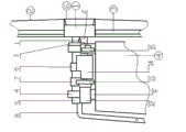
Growth trend motility machine unit front elevation is held in the reciprocal lifting of Fig. 1 door frame.
Among the figure: 1. frame top water tank (counterweight storehouse); 2. water inlet; 3. crown block; 4. door form height frame; 5. crane rope; 6. ballast box; 7. water pump; 8. water reservoir; 9. eduction valve.
The local driving mechanism forward sight of growth trend motility machine enlarged view is held in the reciprocal lifting of Fig. 2 door frame.
1 main bearing seat among the figure; 2 turbines; 3 clutches; 4 main shafts; 5 counterweights affect wheel; 6 synchronous double-action mechanisms; 7 transmission booster engines; 8 generator flywheel and clutches; 9 motors; 10 worm shaft bearings; 11 speed reducers; 12 radiators; 13 transmission shafts; 14 clutches; 15 transmission booster engine supports; 16 speed reducers; 17 motors; 18 generators; 19 worm screws.
Growth trend motility pusher side view is held in the reciprocal lifting of Fig. 3 door frame.
1.-8. same Fig. 1 among the figure; 10. rearmounted steel cable static pulley (widening the steel cable spacing).
1,2,4,5,6,7,8,9,10,11,16,17,18,19 same Fig. 2 among the figure.
Fig. 4 pylon wheel shaft send heavy formula to hold growth trend motility machine front elevation.
1. ballast box among the figure; 2. long-armed; 3. distributed water pipe; 4. pylon; 5. water reservoir; 6. wheel disc and distribution bin; 7. draining (sand) valve.
Fig. 5 pylon wheel shaft send heavy formula to hold growth trend motility machine left side view.
1. 2. 3. 4. 5. 6. 7. identical among the figure with Fig. 4.
14 water inlets among the figure; 16 water pumps.
Fig. 6 pylon wheel shaft send heavy formula to hold growth trend motility machine driving mechanism (left side) side-looking partial enlarged drawing.
Fig. 7 pylon wheel shaft send heavy formula to hold growth trend motility machine driving mechanism (right side) side-looking partial enlarged drawing.
1. 2. 3. 4. 6. identical among the figure with Fig. 4.
1 roller among the figure; 2 push rods; 3 semicircle protruding rails; 4 bearings; 5 hollow spindles; 6 main passive tooth; 7 turbines; 8 water inlets; 9 bearing supports; 10 motors; 11 speed reducers; 12 generators; 13 flywheels and clutch; 14 transmission speedup cabinets; 15 radiators.
Fig. 8 pylon wheel shaft send heavy formula to hold growth trend motility machine distribution bin partial enlarged drawing.
2. long-armed among the figure; 3. distributed water pipe; 4. pylon; 6. wheel disc.
1,2,3,4,5,9,10 same Fig. 8 among the figure.
20 distribution bin among the figure; 21 water valve shells; 22 valve rods; 23 gate valves; 24 water channel holes; 25 hollow spindle walls; The hollow water channel of 26 main shafts; 27 water-dividing chambers.
Embodiment:
The measure of the object of the invention has multiple, and following three kinds of working forms mainly are described:
Door frame back and forth " rising " weighs composition and the working forms that formula is held growth trend motility machine: it mainly is made up of door frame (or oblique frame) structure, lifting lifting gear, counterweight tracting mechanism, limiting brake mechanism and transmission speed increasing mechanism.At first power is provided when promoting counterweight by motor or motor; Behind the speed reducer deceleration force amplifier; The winch of torsion being passed to the lifting lifting gear becomes rope traction power; Power quit work when counterweight was risen to door frame eminence top dead center, and through clutch power was separated with reducing gear, successfully obtained gravitational potential energy capable of using to this.The descending power of counterweight pulls another root and finally is wrapped in the counterweight that is in ground and affects the wire rope on the wheel to form pulling force, because the wire rope pulling affects wheel to rotate along the direction of lineoutofservice signal pull, makes to affect wheel to produce rotating power.Meanwhile, be positioned at an end that affects machine and affect the rotation of wheel, therefore played affecting the effect of wheel speed limit and braking with affecting the coaxial worm decelerating machine restriction that links to each other of wheel.The handle arrangement that the end of worm screw is provided with axle mechanism is used to manually boot turbine rotation.
When the counterweight tracting mechanism sends power; Motor in the limiting brake mechanism is rotated; Drive the worm screw rotation after the drive speed reducer and make turbine rotation then; Also just loosen the restriction that (linking to each other with turbine) is affected wheel gradually, make the wire rope pulling of action edge tractive under the counterweight affect wheel to rotate.Affect when wheel is compelled to rotate, to the coaxial transmission speed increasing mechanism outputting power that is connected in the other end, the transmission speed increasing mechanism improves rotating speed in the process of transmission power step by step, and other mechanical work of the highest rotating speed rotating power input.
The characteristics that the heavy formula of door frame reciprocal " rising " is held growth trend motility machine are: (1) has independently can promote the greater weight jack machinism, and (2) counterweight quality in kind immobilizes more greatly and up and down.(3) counterweight periodic duty up and down reciprocatingly.
2 door frames back and forth " sending " heavy formula hold the composition and the working forms of growth trend motility machine: it mainly by door frame (or tiltedly frame) structure (as among Fig. 1 4.), carry weight mechanism (as among Fig. 1 7., 8., 1., 2. wait), ballast box promotes and tracting mechanism (as among Fig. 3 17,16,6,5 and 5., 9., 3., 6. wait), limiting brake mechanism (as among Fig. 32,9,10,11,19 etc.) and transmission speed increasing mechanism (as among Fig. 3 7) etc. form.When carrying weight, by water pump (as among Fig. 1 7.) (and other conveying mechanism) will (water) or other specific weight pump conveying or water channel diversion to the counterweight storehouse that is in the door frame eminence (as among Fig. 1 1.), successfully obtain gravitational potential energy capable of using to this.Promote ballast box (as among Fig. 1 6.) time; By motor or motor (as among Fig. 3 17) power is provided; Behind speed reducer (as among Fig. 3 16) deceleration force amplifier; With torsion pass to synchronous double-action mechanism (as among Fig. 3 6) drive at last promote and the counterweight of tracting mechanism affect wheel (as among Fig. 3 5) become wire rope (as among Fig. 3 5.) tractive force, power quit work when ballast box (sky) was risen to door frame eminence top dead center, at this moment ballast box suitable for reading with lower end, counterweight storehouse eduction valve (as among Fig. 1 9.) combine and back down eduction valve; Make weight earial drainage in the counterweight storehouse in ballast box, ballast box has just produced bigger gravity like this.
The descending gravity of ballast box pulls this root and is wrapped in counterweight and affects the wire rope on the wheel to form pulling force, because the wire rope pulling affects wheel to rotate along the direction of lineoutofservice signal pull, makes to affect wheel to produce rotating power.Meanwhile, be arranged in to affect and take turns the rotation that the coaxial worm decelerating machine that links (like Fig. 32,9,10,11,19) restriction affects wheel, therefore played affecting the effect of wheel speed limit and braking.
The handle arrangement that the end of worm screw is provided with axle mechanism is used to manually boot.
When counterweight affects wheel to send power; Motor in the limiting brake mechanism (as among Fig. 3 9) is rotated; Drive speed reducer (as among Fig. 3 11) back drives worm screw (as among Fig. 3 19) and rotates turbine (as among Fig. 3 2) is rotated; Also just loosen the restriction that (linking to each other with turbine) is affected wheel gradually, make the wire rope pulling of action edge tractive under the counterweight affect wheel to rotate.Affect when wheel is compelled to rotate; To the coaxial transmission speed increasing mechanism that is connected in the other end (in 7) outputting power like Fig. 2, Fig. 3; The transmission speed increasing mechanism improves rotating speed in the process of transmission power step by step, and other mechanical work of the highest rotating speed rotating power input.
Row unloaded water, husky compelled the opening of valve when ballast box running dropped to the water reservoir top on ground, unloaded to water reservoir to discharge water, and this valve is closed automatically when treating that the ballast box shuttling movement rises once more.
The characteristics that the heavy formula of door frame reciprocal " sending " is held growth trend motility machine are: (1) has conveying and storage weight mechanism, and (2) counterweight empty van weight change in uploading the flow process of unloading down is bigger, and it is same mechanism that the lifting of (3) ballast box affects with counterweight.
[0042] 3 pylon wheel shaft send heavy formula (like windmill shape, waterwheel shape or skyscraping wheel shape etc.) to hold the composition and the working forms of growth trend motility machine: it mainly by pylon structure (as among Fig. 4 4.), wheel shaft gesture actuation mechanism (as among Fig. 4 1., 2., 6., among Fig. 74,5,9), carry (weight) mechanism (as among Fig. 5, Fig. 6 5., 3., 7., 16,14), limiting brake mechanism (as among Fig. 77,10,11) and transmission speed increasing mechanism (as among Fig. 8 12,13,14,15) form.When promote carrying the counterweight weight at first by water pump (as among Fig. 5, Fig. 6 16,14,3.) or conveying mechanisies such as transport tape, screw conveyer, (or with the artificial drop of water channel diversion etc.) with the axle mechanism that counterweight medium transport such as water or sand go up (" windmill " or " ferris wheel " reaches forms such as " waterwheels ") to the pylon top long-armed (as among Fig. 5, Fig. 6 2.) ballast box of end (and as among Fig. 5, Fig. 6 1.) in.
The wheel disc distribution bin (as among Fig. 8 6., 20) working forms:
Water pump is transported to the hollow water channel of main shaft with water through water inlet (in like Fig. 5 14); Arrive water-dividing chamber in the distribution bin (as among Fig. 8 27); When a certain long-armed when running on the pylon peak; (as among Fig. 5, Fig. 6 2.), be arranged in the roller (like Fig. 7 1) of wheel disc back below this long-armed root, on the top be arranged in the semicircle protruding rail (like Fig. 7 3) of main spindle front bearing front upper part; Roller is by protruding rail jack-up; Thereby gate valve that will be through being connected with push rod (as among Fig. 7 2) (as among Fig. 8 23) backs down, make the water that is in water-dividing chamber get into this long-armed distributed water pipe (as among Fig. 8 3.), the upwards last again ballast box that arrives long-armed end (as among Fig. 5, Fig. 6 1.) in.
In addition, also can be provided for the overhead of fixedly pipeline, water pump, water tank and oil filling riser (facility of the defeated charge of oil material of fuel oil storehouse oil supply tank car) in pylon one side, oil filling riser contacts with ballast box with angle in certain height, in the short time water is filled with ballast box.
Long-armed descending power comes from the gravity of the long-armed terminal ballast box of axle mechanism; Be filled weights such as water or sand when ballast box after; Gravity increases and moves downward; Thereby drive wheel disc in the long-armed downlink drive axle mechanism (as among Fig. 4 6.) rotate, be in the hollow spindle that the axle mechanism center is connected with wheel disc (among Fig. 7 5) and also be compelled rotation.At this moment, the turbine (Fig. 7 7) that is arranged in main shaft one end and the concentric worm decelerating machine that links to each other of main shaft is by the worm screw limit rotation, thereby played the effect to the main shaft speed limit.When wheel shaft gesture actuation mechanism is sent power; After at first will making the speed reducer that motor in the limiting brake mechanism (among Fig. 7 10) rotating drive links (among Fig. 7 11); Drive the worm screw rotation and make turbine rotation then; Also just loosen restriction gradually, make the long-armed and main shaft rotation of the descending motivational drive of counterweight main shaft.When main shaft rotates to the meshing transmission speed increasing mechanism of driving tooth (among Fig. 8 6) (among Fig. 8 14) outputting power, the highest other machinery of rotating speed rotating power input (like 12 generator among Fig. 8) acting in self side.
When ballast box running drops to ground row unload water, husky valve (as among Fig. 4 7.) compelled opening, this valve is closed automatically when treating the ballast box shuttling movement to specific eminence.The characteristics that the pylon wheel shaft send heavy formula to hold growth trend motility machine are: (1) pylon axle mechanism produces potential energy-dynamic, the periodic duty of (2) long-armed (or bull wheel) rotation ballast box, and the handle arrangement that the end of (3) worm screw is provided with axle mechanism starts turbine rotation.
Advantage of the present invention is: the combination existing technology, rational in infrastructure, easy to implement, clean ability is efficient, and is of many uses.
The beneficial effect that is brought is: for society a kind of be the energy with gravitation, be the dynamic power machine of the practicality and high efficiency of power with gravitational potential energy, therefore can reduce the use that pollution power sources is arranged.
Claims (10)
1. hold growth trend motility machine, it is characterized in that the working morphology that holds growth trend motility machine has pylon type (like windmill shape, skyscraping wheel shape or waterwheel shape), door frame type and oblique frame rail type etc., working morphology has been confirmed the downstream state of counterweight.
2. the growth trend motility machine that holds as claimed in claim 1 is characterized in that obtaining of gravitational potential energy is to send with pumping, transmission, conveying, strand that (screw conveyer) and water channel diversion form artificial drop, and winch and sheave block etc. rise, the form and the technology of lifting or lifting realize.
3. the growth trend motility machine that holds as claimed in claim 2 is characterized in that it all is by (1), door frame (or oblique frame rail road or pylon structure) structure that each shape is held growth trend motility machine, (
2),Lifting (or promote) mechanism (or carrying the weight mechanism that rises), (3), counterweight affect (wheel) mechanism (or wheel shaft gesture actuation mechanism) (
4)
,Limiting brake mechanism, formations such as (5), transmission speed increasing mechanism, with these technology and contexture one cooperating, circulation up and down reciprocatingly produces lasting rotating power, holds the major character and the function of growth trend motility machine exactly.
4. the various growth trend motility machine that holds as claimed in claim 2; It is characterized in that the descending startup of counterweight, braking and speed are to control with what (main shaft of axle mechanism or counterweight affect wheel) combined with worm decelerating machine; The startup of worm decelerating machine is to control with the gear reduction unit and the motor that link to each other with the end of worm screw with speed; Gear reduction unit and motor that the worm screw of control worm decelerating machine is rotated all can carry out forward and backward; The end of worm screw is provided with the handle arrangement of axle mechanism; Turbine diameter in the worm gear box affects the diameter close (identical) of wheel (or main shaft of wheel shaft gesture actuation mechanism) with counterweight or greater than it; Each worm screw speed limiting mechanism and wheel shaft gesture actuation mechanism main shaft (or affect wheel with counterweight) are combined closely or synchronous interaction, also can worm screw speed limiting mechanism and main shaft be separated and adopt gear transmission or chain-driven to come main shaft is carried out speed limit, or integrally combine with bull wheel (or counterweight affects wheel) in the axle mechanism; The stressed reduction of turbine mechanism is reduced wear, thereby can make the turbine mechanism volume-diminished.
5. the growth trend motility machine that holds as claimed in claim 2; What it is characterized in that various forms holds growth trend motility machine; The diameter (or long-armed length) that counterweight in the axle mechanism that is had affects (greatly) wheel is all than the big several times of diameter of main shaft or tens times; Each form is held growth trend motility machine, is to affect the diameter of (greatly) wheel to strengthen potential energy-dynamic to increase long-armed length as required or to increase counterweight.
6. windmill shape as claimed in claim 2 (skyscraping wheel shape, waterwheel shape) is held growth trend motility machine; It is characterized in that holding the hoisting way of the counterweight medium (water) of growth trend motility machine, alternating pump send, and also can carry out water channel, diverting water through pipeline to certain altitude in the form height low water sources such as river, streams of selecting in base area; Form artificial drop and obtain gravitational potential energy; In the mass pumping mode, when water pump and water inlet were placed in rear-end of spindle, main shaft must be processed hollow; Make in water hollow from main shaft the distributor chamber that is arranged in the distribution bin of front-end of spindle through entering; Water pump and water supply pipeline also can be placed in this type of front portion of holding growth trend motility machine (being the front end of wheel disc and distribution bin), or are provided for the overhead of fixedly pipeline, water pump, water tank and oil filling riser (facility of the defeated charge of oil material of fuel oil storehouse oil supply tank car) in pylon one side, and oil filling riser contacts with ballast box with angle in certain height; At short notice water is filled with the ballast box that is in every long-armed end; Ballast box can be made into square empty van body, hollow ball, hollow cylinder, hollow funnel, and a side of ballast box has distributed water pipe to communicate with distributor chamber, also has drain valve or draining, the husky valve of row at the ballast box special position; Row unloaded water when the ballast box running dropped to ground, husky valve is compelled opens; This valve is closed automatically when treating that the ballast box shuttling movement rises once more, this type of holds growth trend motility machine the long-armed even number (promptly 2,4,6 that is necessary for ...) also can all long-armed linking to each other be processed a bull wheel (becoming the skyscraping wheel shape), the periphery of wheel disc and distribution bin is fixed in long-armed bottom; Distribution bin is greater than distributor chamber; Distributor chamber is positioned at the central position of distribution bin, and distributor chamber is peripheral to distribute gate valve and distributed water pipe with every long-armed corresponding setting up separately, and the distributing valve switching mechanism can be made into post rod type, rocking arm type or wheel shaft type.
7. door frame shape as claimed in claim 2 is held growth trend motility machine, and the top that it is characterized in that door frame sky beam is provided for changing the static pulley that promotes ballast box steel cable direction, and will store up loaded van and also be arranged on the both sides above day beam; Can (as required) movable pulley in the sheave block be arranged on the below of day beam, be provided for widening the static pulley of steel cable and door frame spacing on top, door frame rear portion, a door frame can be provided with a cover and hold growth trend motility mechanism; Also can door frame be widened and two covers are set simultaneously or hold growth trend motility unit more than two covers; Make the periodic duty up and down reciprocatingly of many cover counterweights, the upper end of the water inlet that door frame both sides and door pillar are existed side by side feeds frame top water tank (counterweight storehouse), and lower end and water pump join; Water pump is positioned at the water reservoir top; Water reservoir is positioned at the inboard of door frame column, the below that ballast box is vertical, or water reservoir is arranged on other places; But water channel and gutter must be set below ballast box, and gutter is communicated with one with water reservoir.
8. the growth trend motility machine that holds as claimed in claim 2; It is characterized in that door frame shape, tiltedly the frame orbit-shaped holds during growth trend motility mechanism makes; Counterweight is set affects axle mechanism, it affects wheel, central principal axis, both sides support and bearing and base to form by counterweight, and it is oblate wheel that counterweight affects wheel; Can be vertical or horizontal setting; Be positioned at the size diameter that counterweight affects the chain Moving plate (gear ring or gear) of the power synchronous interaction mechanism of taking turns a side, close with the diameter that affects wheel or big slightly, can save the power that drives the motor that affects wheel (during the steel cable of rolling in the other direction) rotation like this.
9. door frame shape as claimed in claim 2, oblique frame orbit-shaped hold growth trend motility machine; It is characterized in that it is by following parts composite construction: frame top water tank (counterweight storehouse), water inlet, crown block, door form height frame, (or tiltedly frame rail road) crane rope, ballast box, water pump, water reservoir, eduction valve, rearmounted steel cable static pulley, main bearing seat, turbine, clutch, main shaft, counterweight affect wheel, synchronous double-action mechanism, transmission booster engine, generator flywheel and clutch, motor, worm shaft bearing, speed reducer, radiator, transmission shaft, clutch, transmission booster engine support, speed reducer, motor, generator, worm screw.
10. windmill shape as claimed in claim 2 (skyscraping wheel shape, waterwheel shape) is held growth trend motility machine, it is characterized in that it is by following parts composite construction: ballast box, long-armed, distributed water pipe, pylon, water reservoir, wheel disc and distribution bin, draining (sand) valve, roller, push rod, semicircle protruding rail, bearing, hollow spindle, main passive tooth, turbine, water inlet, bearing support, motor, speed reducer, generator, flywheel and clutch, transmission speedup cabinet, radiator.
Priority Applications (1)
| Application Number | Priority Date | Filing Date | Title |
|---|---|---|---|
| CN2012100350063A CN102748251A (en) | 2012-02-16 | 2012-02-16 | Power machine for storing and increasing potential energy |
Applications Claiming Priority (1)
| Application Number | Priority Date | Filing Date | Title |
|---|---|---|---|
| CN2012100350063A CN102748251A (en) | 2012-02-16 | 2012-02-16 | Power machine for storing and increasing potential energy |
Publications (1)
| Publication Number | Publication Date |
|---|---|
| CN102748251A true CN102748251A (en) | 2012-10-24 |
Family
ID=47028677
Family Applications (1)
| Application Number | Title | Priority Date | Filing Date |
|---|---|---|---|
| CN2012100350063A Pending CN102748251A (en) | 2012-02-16 | 2012-02-16 | Power machine for storing and increasing potential energy |
Country Status (1)
| Country | Link |
|---|---|
| CN (1) | CN102748251A (en) |
Cited By (3)
| Publication number | Priority date | Publication date | Assignee | Title |
|---|---|---|---|---|
| WO2014106460A1 (en) * | 2013-01-06 | 2014-07-10 | Meng Lingsong | Closed pressure-enhancing power station, gas station, heat supply station, and engine having artificial fluid and using gravitational energy |
| WO2018196736A1 (en) * | 2017-04-28 | 2018-11-01 | 陈奕多 | Power plant which recycles gravitational potential energy and water circulation energy |
| CN110185590A (en) * | 2019-05-30 | 2019-08-30 | 贾建龙 | A kind of energy transfer power energy system |
-
2012
- 2012-02-16 CN CN2012100350063A patent/CN102748251A/en active Pending
Cited By (3)
| Publication number | Priority date | Publication date | Assignee | Title |
|---|---|---|---|---|
| WO2014106460A1 (en) * | 2013-01-06 | 2014-07-10 | Meng Lingsong | Closed pressure-enhancing power station, gas station, heat supply station, and engine having artificial fluid and using gravitational energy |
| WO2018196736A1 (en) * | 2017-04-28 | 2018-11-01 | 陈奕多 | Power plant which recycles gravitational potential energy and water circulation energy |
| CN110185590A (en) * | 2019-05-30 | 2019-08-30 | 贾建龙 | A kind of energy transfer power energy system |
Similar Documents
| Publication | Publication Date | Title |
|---|---|---|
| US8648486B2 (en) | Method and system for tidal energy storage and power generation | |
| US20130291532A1 (en) | Tidal Energy Seawater Desalination System, Power Generation System and Integral Energy Utilization System | |
| AU2006352636B2 (en) | Lifting device, power generation device and sea reverse osmosis device | |
| CN102828891B (en) | Wave power generation system with floating body, wire cables and rack flywheel group | |
| CN102748251A (en) | Power machine for storing and increasing potential energy | |
| CN202001178U (en) | Tidal power generation system and storage system and multiplying power increasing system thereof | |
| WO2015078097A1 (en) | System for preparing compressed air using weight potential energy | |
| CN102678438A (en) | Floating plumbing body and flywheel plumbing arm self-energy generator | |
| GB2551177A (en) | Raised weight gravity generator | |
| CN108150622A (en) | A kind of accumulating mechanism and its application | |
| GB2522092A (en) | Rigid body dynamics-based hydropower technology | |
| CN205779445U (en) | Array float-type wave energy generating set | |
| CN1800627A (en) | Oar wheel type automatic water pumping machine with falling water kinetic energy conversion function | |
| CN2926566Y (en) | Gantry hydraulic generator | |
| CN105003382B (en) | Wind driving hydroelectric power generation equipment | |
| CN109695552A (en) | A kind of accumulating mechanism and its application | |
| CN102966483A (en) | Hydraulically circulatory generator | |
| CN203383971U (en) | Megawatt phase reversion conveyor-type impeller hydroelectric generation system | |
| CN108547724B (en) | Hydroelectric power generation system capable of utilizing kinetic energy of residual water of hydroelectric power generation | |
| CN105003399A (en) | Power generation system utilizing rolling compaction force of wheels to pavement for power generation | |
| CN205001132U (en) | Utilize wheel to grind pressure generation's power generation system to road surface | |
| CN101639049A (en) | Power generation system and method from wind | |
| CN103982371A (en) | Vertical buoyancy lift sedimentation power output device | |
| CN1395040A (en) | Pendulum engine | |
| CN203104205U (en) | Sucker rod drive device of pumping unit |
Legal Events
| Date | Code | Title | Description |
|---|---|---|---|
| C06 | Publication | ||
| PB01 | Publication | ||
| C02 | Deemed withdrawal of patent application after publication (patent law 2001) | ||
| WD01 | Invention patent application deemed withdrawn after publication |
Application publication date: 20121024 |