CN102733885A - System and method for monitoring engine oil levels - Google Patents
System and method for monitoring engine oil levels Download PDFInfo
- Publication number
- CN102733885A CN102733885A CN2012100988981A CN201210098898A CN102733885A CN 102733885 A CN102733885 A CN 102733885A CN 2012100988981 A CN2012100988981 A CN 2012100988981A CN 201210098898 A CN201210098898 A CN 201210098898A CN 102733885 A CN102733885 A CN 102733885A
- Authority
- CN
- China
- Prior art keywords
- fluid
- oil
- fluid position
- determination module
- liquid level
- Prior art date
- Legal status (The legal status is an assumption and is not a legal conclusion. Google has not performed a legal analysis and makes no representation as to the accuracy of the status listed.)
- Granted
Links
Images


Classifications
-
- F—MECHANICAL ENGINEERING; LIGHTING; HEATING; WEAPONS; BLASTING
- F01—MACHINES OR ENGINES IN GENERAL; ENGINE PLANTS IN GENERAL; STEAM ENGINES
- F01M—LUBRICATING OF MACHINES OR ENGINES IN GENERAL; LUBRICATING INTERNAL COMBUSTION ENGINES; CRANKCASE VENTILATING
- F01M11/00—Component parts, details or accessories, not provided for in, or of interest apart from, groups F01M1/00 - F01M9/00
- F01M11/10—Indicating devices; Other safety devices
- F01M11/12—Indicating devices; Other safety devices concerning lubricant level
Landscapes
- Engineering & Computer Science (AREA)
- Mechanical Engineering (AREA)
- General Engineering & Computer Science (AREA)
- Lubrication Details And Ventilation Of Internal Combustion Engines (AREA)
Abstract
A system includes a user interface module, a level determination module, and a level storage module. The user interface module outputs an oil level request based on user input. The level determination module determines N oil levels of an engine. N is an integer greater than one. The level storage module stores the N oil levels and outputs one of the N oil levels in response to the oil level request.
Description
Technical field
The present invention relates to engine control system and method, more specifically, relate to the system and method that is used to monitor the engine oil liquid level.
Background technique
The purpose of description of background technique provided herein is generally to provide background of the present disclosure.The inventor's of current signature work, in the described degree of this background technique part, and when submitting to, possibly not constitute aspect existing technology of the present invention be not to show clearly or impliedly be accepted as existing technology of the present disclosure.
Engine oil circulates with the moving link in the lubricating engine in motor usually.Usually, oil pump is pumped into in-engine various other position with engine oil from oily storage tank.Gravity causes engine oil to be back to oily storage tank.When motor was closed, oil pump is the pumping engine oil no longer, and therefore the major part of engine oil is back to oily storage tank and is retained in the oily storage tank.
When motor moved, engine oil must remain on certain liquid level preventing engine component is caused damage.Developed such method, that is, when tail-off, the operator is through being deposited on the amount of the oil on the oil meter and manually checking the engine oil liquid level from oily storage tank taking-up oil meter and observation.Therefore yet these methods depend on the operator and check the engine oil liquid level, possibly cause not running check fluid position, low or high engine oil liquid level, and finally damage motor and/or emission control systems.
Summary of the invention
A kind of system, this system comprise Subscriber Interface Module SIM, liquid level determination module and liquid level memory module.Subscriber Interface Module SIM is exported fluid position request based on user's input.The liquid level determination module is confirmed N fluid position of motor.N is the integer greater than 1.The liquid level memory module is stored N fluid position, and exports one of N fluid position in response to the request of fluid position.
In addition, the invention still further relates to following technological scheme.
1. system comprises:
Export fluid position requesting users Interface Module based on user's input;
Confirm the liquid level determination module of N fluid position of motor; And
Liquid level memory module, said liquid level memory module are stored said N fluid position, and export one of said N fluid position in response to the position request of said fluid, and wherein, N is the integer greater than 1.
2. like technological scheme 1 described system; Also comprise the fluid level sensor, said fluid level sensor is measured the fluid position, and the fluid position signal of said N fluid position of output indication; Wherein, said liquid level determination module is confirmed said N fluid position based on said fluid position signal.
3. like technological scheme 1 described system, also comprise the temperature determination module of the oil temperature of confirming said motor, wherein, said liquid level determination module is confirmed said N fluid position based on said oily temperature.
4. like technological scheme 3 described systems, also comprise temperature transducer, said temperature sensor measurement oil temperature, and the oil temperature signal of output indication oil temperature, wherein, said temperature determination module is confirmed the oil temperature based on said oil temperature signal.
5. like technological scheme 3 described systems, wherein, when said oil temperature during greater than predetermined temperature, said liquid level determination module is confirmed said N fluid position.
6. like technological scheme 3 described systems; Also comprise the time determination module; Said time determination module is confirmed oil the releasing the time in the oil cup that gets into motor that be allowed to release; Wherein, release during the time greater than said when the tail-off time, said liquid level determination module is confirmed said N fluid position.
7. like technological scheme 6 described systems, wherein, said time determination module is confirmed said releasing the time based in oil temperature, engine type and the oil viscosity grade at least one.
8. like technological scheme 1 described system, comprise also and confirm the inclination determination module of vehicle that wherein, when the inclination of vehicle during less than predetermined angle, said liquid level determination module is confirmed said N fluid position with respect to the inclination of gravity.
9. like technological scheme 1 described system, wherein, said liquid level determination module is confirmed one of said N fluid position in response to the position request of said fluid.
10. like technological scheme 1 described system, wherein, utilize position request of the said fluid of wireless signal transfer and said fluid position.
11. a method comprises:
Export fluid position request based on user's input;
Confirm N fluid position of motor; And
In nonvolatile memory, store said N fluid position, and export one of said N fluid position in response to the position request of said fluid, wherein, N is the integer greater than 1.
12., also comprise like technological scheme 11 described methods:
Measure the fluid position, and the fluid position signal of said N fluid position of output indication; And
Confirm said N fluid position based on said fluid position signal.
13., also comprise like technological scheme 11 described methods:
Confirm the oil temperature of said motor; And
Confirm said N fluid position based on said oil temperature.
14., also comprise like technological scheme 13 described methods:
The oil temperature signal of output indication oil temperature; And
Confirm said oil temperature based on said oil temperature signal.
15., also comprise:, confirm said N fluid position when said oil temperature during greater than predetermined temperature like technological scheme 13 described methods.
16., also comprise like technological scheme 13 described methods:
Definite oil releasing the time of the oil cup that gets into said motor that be allowed to release; And
Release during the time greater than said when the tail-off time, confirm said N fluid position.
17., also comprise: confirm said releasing the time based in oil temperature, engine type and the oil viscosity grade at least one like technological scheme 16 described methods.
18., also comprise like technological scheme 11 described methods:
Confirm the inclination of vehicle with respect to gravity; And
When the inclination of vehicle is confirmed said N fluid position during less than predetermined angle.
19., also comprise: confirm one of said N fluid position in response to the position request of said fluid like technological scheme 11 described methods.
20., wherein, utilize position request of the said fluid of wireless signal transfer and said fluid position like technological scheme 11 described methods.
Applicable other field of the present disclosure will become clear from detailed description provided below.Should be appreciated that detailed description and instantiation only are to be used for illustrative purposes, and do not limit the scope of the present disclosure.
Description of drawings
From specifying and accompanying drawing, the disclosure will more fully be understood, in the accompanying drawing:
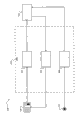
Fig. 1 is the functional block diagram of exemplary engine system in accordance with the principles of the present invention;
Fig. 2 is the functional block diagram of example user interface module in accordance with the principles of the present invention;
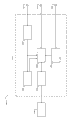
Fig. 3 is the functional block diagram of exemplary engine control module in accordance with the principles of the present invention; With
Fig. 4 and Fig. 5 are the flow charts that the exemplary method of monitoring engine oil in accordance with the principles of the present invention is shown.
Embodiment
Below being described in only is illustrative in essence, and never intention limits the disclosure, its application or purposes.For clear, use identical label to represent similar element in the accompanying drawings.As used herein, phrase A, at least one among B and the C should be understood that presentation logic (A or B or C), the logic OR that the right and wrong of use are exclusive.Should understand that the step in the method can be carried out with different orders, and does not change principle of the present disclosure.
As used herein, term module can refer to a part for or comprise: ASIC (ASIC); Circuit; Combinational logic circuit; Field programmable gate array (FPGA); The processor of run time version (shared, special-purpose or in groups); Other suitable member of required function is provided; Perhaps more above-described combination is such as SOC(system on a chip).Term module can comprise the storage (shared, special-purpose or in groups) of the code that storage is carried out by processor.
The term code like above usefulness, can comprise software, firmware and/or microcode, and can refer to program, routine, function, class and/or object.Term is shared, and is as above used, and the some or all of codes that refer to from a plurality of modules can utilize single (sharing) processor to carry out.In addition, can store by single (sharing) storage from the some or all of codes of a plurality of modules.Term in groups, as above used, the some or all of codes that refer to from individual module can utilize one group of processor to carry out.In addition, the some or all of codes from individual module can utilize storage stack to store.
Apparatus and method as herein described can be implemented by the performed one or more computer programs of one or more processors.Computer program comprises the processor executable that is stored on the tangible computer-readable medium of nonvolatile property.Computer program can also comprise the data of storage.The non-limiting example of the tangible computer-readable medium of nonvolatile property is nonvolatile memory, magnetic memory apparatus and optical storage.
Engine oil level monitoring system and the method fluid position of detection of engine automatically makes the user can ask the inspection of fluid position, and shows the fluid position in response to user's request in accordance with the principles of the present invention.The fluid position can use the fluid level sensor to measure.The user can the instrumentation plate, the fluid position is asked in shifter and/or internet.In response to user's request, can confirm the fluid position based on oil monitoring situation.
Oil monitoring situation can comprise oil temperature, tail-off time and/or vehicle tilt.When oil temperature during less than predetermined angle, can be confirmed the fluid position greater than the time of releasing and/or vehicle tilt greater than predetermined temperature, tail-off time.Can revise the fluid position based on oily temperature, oily temperature can utilize temperature transducer to measure.At the time durations of releasing, allow oil to release in the oil cup, the time of releasing can be confirmed based on oil temperature, engine type and/or oil viscosity grade.
With reference now to Fig. 1,, shows the functional block diagram of exemplary engine system 100.Motor 102 produces the driving torque that is used for vehicle.Though motor 102 is illustrated and will discusses as spark ignition type, motor 102 can be the motor of another suitable type, for example compression ignition engine.
Air is inhaled into motor 102 through intake manifold 104.Can use throttler valve 106 to change the air-flow that gets into motor 102.One or more fuel injectors, for example fuel injector 108, make fuel and air mixing to form air/fuel mixture.Air/fuel mixture is in cylinder (the for example cylinder 110) internal combustion of motor 102.Although motor 102 is described to comprise a cylinder, motor 102 can comprise the cylinder more than.
During combustion phase, from the spark ignition air/fuel mixture of spark plug 114.The combustion driven piston of air/fuel mixture is backward towards position, the end, and the rotation of piston actuated bent axle 112.The exhaust that produces is discharged to accomplish exhaust phase and burn cycle through gas exhaust manifold 116 from cylinder 110.Motor 102 is exported to the speed changer (not shown) via bent axle 112 with moment of torsion.
The oil of the moving element in oil cup 118 (such as oily storage tank) the storage lubricating engine 102, and can be positioned near the bottom or bottom of motor 102.When motor 102 operations, oily storage tank (not shown) can be pumped into other position in the motor 102 from oil cup 118 with oil.Gravity possibly cause oil to turn back to oil cup 118.When motor 102 was closed, oil pump can stop pump oil, and the major part of oil can be back to oil cup 118 and be retained in the oil cup 118.
Engine control module (ECM) 120 is controlled throttler valve 106, fuel injector 108 and spark plug 114 based on the input that receives from one or more sensors, and the fluid position of definite tilt angle, oily gentle motor 102.ECM120 can control throttler valve 106, fuel injector 108 and spark plug 114 based on the fluid position of motor 102.For example, when the fluid position is low, the speed that ECM120 can limiting engine 102.
Sensor can comprise temperature transducer 122, fluid level sensor 124 and inclination sensor 126.Temperature transducer 122 is measured the temperature of the oil in the motor 102, and the oil temperature signal of output indication oil temperature.The fluid position that fluid level sensor 124 is measured in the motor 102, and the fluid position signal of output indication fluid position.Inclination sensor 126 measuring vehicle are with respect to the inclination of gravity, and the vehicle tilt signal of output indication vehicle tilt.
Subscriber Interface Module SIM (UIM) 128 makes the user can ask the inspection of fluid position and utilizes display unit 130 (such as touch screen) that the fluid position is shown to the user.UIM128 and/or display unit 130 can be included in instrument panel, shifter, laptop computer or the desktop computer.UIM128 utilizes wired or wireless signal and ECM120 is exported in user's request, and ECM120 utilizes wired or wireless signal that UIM128 is exported in the fluid position in response to user's request.
Ignition key or button 132 can start and shutting engine down 102 user.Ignition key or button 132 can be exported to UIM128 with engine start/stop signal, and it can pass to ECM120 with engine start/stop signal.Perhaps, ignition key or button 132 can directly be exported to ECM120 with engine start/stop signal.ECM120 starts in response to engine start/stop signal and shutting engine down 102.
With reference now to Fig. 2,, engine oil level monitoring system 200 comprises ECM120, UIM128 and display unit 130.UIM128 comprises request generation module 202, shows determination module 204 and tail-off timer module 206.Request generation module 202 receives user's input from display unit 130, and imports the fluid position request that produces based on the user.
Show that determination module 204 control display unit 130 are to show from the fluid position that ECM120 receives.When the current oil liquid level was asked, ECM120 can notify and show that determination module 204ECM120 has received current liquid level request.Thereby, show that determination module 204 can control display unit 130 and inform with demonstration and receive current liquid level requesting users message.For example, user message can indicate the user that vehicle is parked on the level ground, and notifies the user that next chance after motor 102 cuts out is carried out the inspection of fluid position.
Tail-off timer module 206 is confirmed the tail-off time, and this time begins when motor 102 is closed and can when motor 102 is activated, finish.Tail-off timer module 206 can be confirmed the tail-off time based on the input that receives from ignition key or button 132.For example, when ignition key or button 132 are pressed to kill engine 102 the time, tail-off timer module 206 can begin to increase the tail-off time.Tail-off timer module 206 can be exported to ECM120 with the tail-off time.
With reference now to Fig. 3,, engine oil level monitoring system 300 comprises ECM120, temperature transducer 122, fluid level sensor 124, inclination sensor 126 and UIM128.System 200,300 can be integrated into single system and can comprise the element of arbitrary system.ECM120 comprises temperature determination module 302, inclination determination module 304, the time determination module 306 of releasing, liquid level determination module 308 and liquid level memory module 310.
The time determination module 306 of releasing is confirmed the time of releasing.The time of releasing is that oil is allowed to release time (for example, between 2 minutes and 30 minutes) of oil return storage 118 when motor 102 cuts out.The time determination module 306 of releasing can be confirmed the time of releasing based on oil temperature, engine type and/or oil viscosity grade.The time determination module 306 of releasing can utilize equality and/or question blank that one or more these factors and the time of releasing are connected to confirm the time of releasing.Time determination module 306 outputs of releasing are released the time.
The oil viscosity grade is the oil viscosity in reference temperature.The oil viscosity grade can influence the time of releasing, and has and releases slowly than the oil of low viscosity grade because have the oil ratio of viscosity higher grade.The oil temperature can influence the time of releasing, because oil viscosity is directly related with the oil temperature.Therefore, when oil was heated, oil viscosity reduced, and oil is released sooner.On the contrary, when oil was cooled, oil viscosity increased, and oil is released slowlyer.Engine type can influence the time of releasing, because different engine types can have different oily passway structures, such as different oily passage diameters, it can influence oily flow.
Liquid level determination module 308 is confirmed the fluid position of motor 102.Liquid level determination module 308 can be confirmed the fluid position based on the relation that limits in advance between fluid position signal and fluid position signal and the fluid position.Perhaps, liquid level determination module 308 can be confirmed the fluid position based on the relation that limits in advance between fluid position signal, oil temperature and fluid position signal, oil temperature and the fluid position.These relations can be implemented as equation and/or question blank.Liquid level determination module 308 output fluid positions.
Liquid level determination module 308 can be confirmed the fluid position and/or when by 310 instructions of liquid level memory module, confirm the fluid position in the predetermined time.Hour number (for example, per 10 hours) and/or motor 102 pent number of times (for example, per 5 times) that the predetermined time can use vehicle mileage (for example, per 500 miles), motor 102 to operate are stipulated.
In addition, when oil monitoring condition satisfied some criterion, such as closing when motor 102 and vehicle when being level, liquid level determination module 308 can be confirmed the fluid position.For example, when oil temperature greater than predetermined temperature, tail-off time greater than the time of releasing and/or vehicle tilt during less than predetermined angle (for example, 30 degree), liquid level determination module 308 can be confirmed the fluid position.Liquid level determination module 308 can receive the tail-off time from UIM128 through liquid level memory module 310, and perhaps liquid level determination module 308 can directly receive the tail-off time from UIM128.
Liquid level memory module 310 is stored the fluid positions, and based on the request of fluid position UIM128 is exported in the fluid position.When the request of fluid position was the request of previous fluid position, liquid level memory module 310 can be exported to UIM128 with previous fluid position.Previous fluid position can be the fluid position of measuring recently.When the request of fluid position was the request of current oil liquid level, liquid level memory module 310 can notify UIM128ECM120 to receive current liquid level request.In addition, liquid level memory module 310 can instruct liquid level determination module 308 to confirm the current oil liquid level.As response, liquid level determination module 308 can be confirmed the current oil liquid level and can the current oil liquid level be exported to liquid level memory module 310.Liquid level memory module 310 can be exported to UIM128 with the current oil liquid level then.
With reference now to Fig. 4,, engine oil monitoring method 400 starts from 402.Method 400 can be carried out by UIM128.404, method 400 confirms whether the user has asked previous fluid position.Previous fluid position can be the fluid position of measuring recently.If 404 is true, then this method 400 proceeds to 406.Otherwise method 400 proceeds to 408.
406, method 400 utilizes wired or wireless signal that vehicle modules is exported in previous liquid level request, such as ECM.410, method 400 determines whether to receive previous fluid position from vehicle modules.If 410 is true, then this method 400 proceeds to 412.412, method 400 shows previous fluid position.Method 400 also can show date, time and the vehicle mileage corresponding to previous fluid position.
408, method 400 confirms whether the user has asked the current oil liquid level.If 408 is true, then this method 400 proceeds to 414.Otherwise method 400 finishes 416.414, method 400 is exported to vehicle modules with current liquid level request.Method 400 can utilize wired or wireless signal to export current liquid level request.418, method 400 confirms whether vehicle modules receives current liquid level request.If 418 is true, method 400 proceeds to 420, and display message, and this message can instruct the user stopping on the level ground and notify the user that next chance after closing is carried out the inspection of fluid position.
422, method 400 determines whether to receive the current oil liquid level from vehicle modules.If 422 is true, then this method 400 proceeds to 424.424, method 400 shows the current oil liquid level.Method 400 also can show date, time and the vehicle mileage corresponding to the current oil liquid level.
With reference now to Fig. 5,, engine oil monitoring method 500 starts from 502.Method 400,500 can be integrated into single method and can comprise the step of arbitrary method.Method 500 can be carried out by ECM120.504, method 500 determines whether to have asked previous fluid position.Previous fluid position can be the fluid position of measuring recently.If 504 is true, then this method 500 proceeds to 506.Otherwise method 500 proceeds to 508.
506, the previous fluid of method 500 outputs position.Method 500 can utilize wired or wireless signal vehicle modules to be exported in previous fluid position and/or away from the module of vehicle.Vehicle modules can be included in the instrument panel.Far module can be included in shifter, laptop computer and/or the desktop computer.Method 500 also exportable date, time and vehicle mileage corresponding to previous fluid position.
508, method 500 determines whether to have asked the current oil liquid level.If 508 is true, then this method 500 proceeds to 510.Otherwise method 500 finishes 512.510, method 500 outputs are informed and are received current liquid level requesting users message.Method 500 can be exported to vehicle modules and/or far module with user message.User message may be displayed on instrument panel, shifter, laptop computer and/or the desktop computer.
514, method 500 confirms whether motor is closed.If 514 is true, then this method 500 proceeds to 516.516, method 500 confirms that whether vehicle tilt is less than predetermined angle (for example, 30 degree).If 516 is true, then this method 500 proceeds to 518.Otherwise method 500 finishes 512.
518, method 500 is confirmed the oil temperature.Method 500 can utilize temperature transducer to confirm the oil temperature.520, method 500 confirms that whether oily temperature is greater than predetermined temperature.Predetermined temperature can be the temperature (for example, zero degrees celsius) of fluid level sensor cisco unity malfunction when being lower than this temperature.If 520 is true, then this method 500 proceeds to 522.
522, method 500 is confirmed the time of releasing.The time of releasing is that oil is allowed to release time of oil return storage when tail-off.Method 500 can be confirmed the time of releasing based on oil temperature, engine type and/or oil viscosity grade.524, method 500 confirms that whether the tail-off time is greater than the time of releasing.If 524 is true, then this method 500 proceeds to 526.
526, method 500 is confirmed the current oil liquid level and is exported the current oil liquid level.Method 500 can utilize the fluid level sensor to confirm the current oil liquid level.In addition, method 500 can be confirmed the current oil liquid level based on the oil temperature.Method 500 can be stored the current oil liquid level in nonvolatile memory.
In the predetermined time, if 508 be false, then method can proceed to 514 rather than finish 512.The predetermined time can stipulate with the hour number and/or the pent number of times of motor of vehicle mileage, power operation.If 514,516,520 and 524 is true, then this method 500 can proceed to 526.526, method 500 can be confirmed the fluid position and the fluid position is stored in the nonvolatile memory.506, if the fluid position is the fluid position that is stored in recently in the nonvolatile memory, then method 500 can be output as previous fluid position with the fluid position.
Wide in range instruction of the present disclosure can be implemented in a variety of forms.Therefore, although the disclosure comprises concrete instance, true scope of the present disclosure should not receive this restriction, because after having studied accompanying drawing, specification and claim, those skilled in the art will know other remodeling.
Claims (10)
1. system comprises:
Export fluid position requesting users Interface Module based on user's input;
Confirm the liquid level determination module of N fluid position of motor; And
Liquid level memory module, said liquid level memory module are stored said N fluid position, and export one of said N fluid position in response to the position request of said fluid, and wherein, N is the integer greater than 1.
2. the system of claim 1; Also comprise the fluid level sensor, said fluid level sensor is measured the fluid position, and the fluid position signal of said N fluid position of output indication; Wherein, said liquid level determination module is confirmed said N fluid position based on said fluid position signal.
3. the system of claim 1 also comprises the warm temperature determination module of oil of confirming said motor, and wherein, said liquid level determination module is confirmed said N fluid position based on said oily temperature.
4. system as claimed in claim 3 also comprises temperature transducer, said temperature sensor measurement oil temperature, and the oil temperature signal of output indication oil temperature, and wherein, said temperature determination module is confirmed the oil temperature based on said oil temperature signal.
5. system as claimed in claim 3, wherein, when said oil temperature during greater than predetermined temperature, said liquid level determination module is confirmed said N fluid position.
6. system as claimed in claim 3; Also comprise the time determination module; Said time determination module is confirmed oil the releasing the time in the oil cup that gets into motor that be allowed to release; Wherein, release during the time greater than said when the tail-off time, said liquid level determination module is confirmed said N fluid position.
7. system as claimed in claim 6, wherein, said time determination module is confirmed said releasing the time based in oil temperature, engine type and the oil viscosity grade at least one.
8. the system of claim 1 also comprises and confirms the inclination determination module of vehicle with respect to the inclination of gravity, and wherein, when the inclination of vehicle during less than predetermined angle, said liquid level determination module is confirmed said N fluid position.
9. the system of claim 1, wherein, said liquid level determination module is confirmed one of said N fluid position in response to the position request of said fluid.
10. method comprises:
Export fluid position request based on user's input;
Confirm N fluid position of motor; And
In nonvolatile memory, store said N fluid position, and export one of said N fluid position in response to the position request of said fluid, wherein, N is the integer greater than 1.
Applications Claiming Priority (2)
| Application Number | Priority Date | Filing Date | Title |
|---|---|---|---|
| US13/082,798 | 2011-04-08 | ||
| US13/082,798 US9316132B2 (en) | 2011-04-08 | 2011-04-08 | System and method for monitoring engine oil levels |
Publications (2)
| Publication Number | Publication Date |
|---|---|
| CN102733885A true CN102733885A (en) | 2012-10-17 |
| CN102733885B CN102733885B (en) | 2015-02-25 |
Family
ID=46875353
Family Applications (1)
| Application Number | Title | Priority Date | Filing Date |
|---|---|---|---|
| CN201210098898.1A Active CN102733885B (en) | 2011-04-08 | 2012-04-06 | System and method for monitoring engine oil levels |
Country Status (3)
| Country | Link |
|---|---|
| US (1) | US9316132B2 (en) |
| CN (1) | CN102733885B (en) |
| DE (1) | DE102012205542B4 (en) |
Cited By (3)
| Publication number | Priority date | Publication date | Assignee | Title |
|---|---|---|---|---|
| CN107542584A (en) * | 2016-06-28 | 2018-01-05 | 通用汽车环球科技运作有限责任公司 | Liquid level for vehicle reservoir indicates |
| CN109667641A (en) * | 2017-10-13 | 2019-04-23 | 大众汽车有限公司 | For monitoring the method and driving assembly of the characteristic of engine oil |
| CN116085089A (en) * | 2023-03-21 | 2023-05-09 | 重庆长安汽车股份有限公司 | Engine oil amount detection method, engine oil amount detection device, electronic equipment, vehicle and storage medium |
Families Citing this family (7)
| Publication number | Priority date | Publication date | Assignee | Title |
|---|---|---|---|---|
| US9404403B2 (en) * | 2011-04-08 | 2016-08-02 | GM Global Technology Operations LLC | Engine oil level monitoring systems and methods |
| US9316132B2 (en) | 2011-04-08 | 2016-04-19 | GM Global Technology Operations LLC | System and method for monitoring engine oil levels |
| US20130226392A1 (en) * | 2012-02-29 | 2013-08-29 | GM Global Technology Operations LLC | Systems and methods for advising customers regarding vehicle operation and maintenance |
| CN104481632A (en) * | 2014-11-25 | 2015-04-01 | 浙江吉利汽车研究院有限公司 | Oil pressure detecting device for engine |
| US9982580B2 (en) | 2015-03-30 | 2018-05-29 | GM Global Technology Operations LLC | Adaptation of a wireless oil level sensor to an oil pan drain plug |
| US10527523B2 (en) | 2015-12-18 | 2020-01-07 | Ge Global Sourcing Llc | Vehicle sensor assembly having an RF sensor disposed in the sensor assembly to wirelessly communicate data to outside the sensor assembly |
| KR102420666B1 (en) * | 2017-12-21 | 2022-07-14 | 현대자동차주식회사 | Vehicle and engine off timer diagnosis method thereof |
Citations (4)
| Publication number | Priority date | Publication date | Assignee | Title |
|---|---|---|---|---|
| US4367462A (en) * | 1981-01-05 | 1983-01-04 | Minnesota Mining And Manufacturing Company | Liquid level sensing circuitry |
| US5019800A (en) * | 1988-10-01 | 1991-05-28 | Gustav Gallert | System for measuring the oil level of an oil pan of the crankcase of an internal combustion engine |
| US6301947B1 (en) * | 1999-03-19 | 2001-10-16 | Daimlerchrysler Corporation | Fluid level indicator that compensates for fluid temperature |
| US7129715B2 (en) * | 2001-09-28 | 2006-10-31 | Ngk Spark Plug Co., Ltd. | Oil deterioration sensor |
Family Cites Families (29)
| Publication number | Priority date | Publication date | Assignee | Title |
|---|---|---|---|---|
| US1432346A (en) * | 1922-10-17 | Electrical indicator | ||
| JPS5216528B2 (en) * | 1973-08-11 | 1977-05-10 | ||
| US4023137A (en) * | 1975-07-28 | 1977-05-10 | Ab Volvo Penta | Device for indicating the oil level in a combustion engine crankcase |
| US4503419A (en) * | 1983-01-17 | 1985-03-05 | General Motors Corporation | Oil level detection circuit |
| US5006829A (en) | 1987-03-31 | 1991-04-09 | Honda Giken Kogyo K.K. | Information display system for a vehicle |
| US5159313A (en) * | 1989-06-19 | 1992-10-27 | Toyota Jidosha Kabushiki Kaisha | Oil supply system in an internal combustion engine for a vehicle |
| JPH03210068A (en) | 1990-01-12 | 1991-09-13 | Mitsubishi Electric Corp | Engine control unit |
| US5369396A (en) * | 1992-05-14 | 1994-11-29 | Toyota Jidosha Kabushiki Kaisha | Apparatus for detecting a level of liquid |
| US5730026A (en) * | 1995-03-31 | 1998-03-24 | Josef Maatuk | Microprocessor-based liquid sensor and ice detector |
| DE19602599C2 (en) * | 1996-01-25 | 2002-07-11 | Daimler Chrysler Ag | Method for determining a quantity of liquid, in particular the quantity of engine oil, in a motor vehicle |
| US6694285B1 (en) | 1999-03-13 | 2004-02-17 | Textron System Corporation | Method and apparatus for monitoring rotating machinery |
| US6429773B1 (en) * | 2000-10-31 | 2002-08-06 | Hewlett-Packard Company | System for remotely communicating with a vehicle |
| US20020177960A1 (en) * | 2001-05-24 | 2002-11-28 | Berndorfer Axel H. | System and method for measuring vehicle engine oil level |
| US6587767B2 (en) * | 2001-09-21 | 2003-07-01 | Detroit Diesel Corporation | Maintenance alert system for heavy-duty trucks |
| US6768938B2 (en) | 2001-11-16 | 2004-07-27 | Goodrich Pump & Engine Control Systems, Inc. | Vibration monitoring system for gas turbine engines |
| US6634113B1 (en) | 2002-05-17 | 2003-10-21 | Delphi Technologies, Inc. | Tilt sensor and method of forming such device |
| US6914524B2 (en) * | 2003-02-27 | 2005-07-05 | Delphi Technologies, Inc. | Apparatus and method for detecting ignition and engine conditions |
| JP4409927B2 (en) | 2003-12-09 | 2010-02-03 | 本田技研工業株式会社 | Hydraulic oil change display for automatic transmission |
| US20050126282A1 (en) * | 2003-12-16 | 2005-06-16 | Josef Maatuk | Liquid sensor and ice detector |
| DE102004039836B4 (en) | 2004-08-17 | 2016-06-23 | Continental Automotive Gmbh | Method and device for detecting a fuel input into the lubricating oil of an internal combustion engine |
| CN100567711C (en) | 2005-06-23 | 2009-12-09 | 本田技研工业株式会社 | Engine oil level detection system |
| US20070169549A1 (en) * | 2006-01-23 | 2007-07-26 | Southwest Research Institute | Method and apparatus for sensing fuel levels in tanks |
| US7904229B2 (en) | 2007-09-18 | 2011-03-08 | Hamilton Sundstrand Corporation | Method for determination of engine lubrication oil consumption |
| US8127597B2 (en) | 2008-01-28 | 2012-03-06 | GM Global Technology Operations LLC | Oil condition sensing methods and systems |
| US8401760B2 (en) | 2009-07-07 | 2013-03-19 | Honeywell International Inc. | Gas turbine engine oil consumption monitoring system and method |
| US8659413B2 (en) * | 2010-11-23 | 2014-02-25 | Caterpillar Inc. | Fluid level monitoring system and method |
| US9404403B2 (en) | 2011-04-08 | 2016-08-02 | GM Global Technology Operations LLC | Engine oil level monitoring systems and methods |
| US9316132B2 (en) | 2011-04-08 | 2016-04-19 | GM Global Technology Operations LLC | System and method for monitoring engine oil levels |
| US8887509B2 (en) | 2012-03-02 | 2014-11-18 | Hamilton Sundstrand Corporation | Liquid level monitoring and reporting system |
-
2011
- 2011-04-08 US US13/082,798 patent/US9316132B2/en not_active Expired - Fee Related
-
2012
- 2012-04-04 DE DE102012205542.8A patent/DE102012205542B4/en active Active
- 2012-04-06 CN CN201210098898.1A patent/CN102733885B/en active Active
Patent Citations (4)
| Publication number | Priority date | Publication date | Assignee | Title |
|---|---|---|---|---|
| US4367462A (en) * | 1981-01-05 | 1983-01-04 | Minnesota Mining And Manufacturing Company | Liquid level sensing circuitry |
| US5019800A (en) * | 1988-10-01 | 1991-05-28 | Gustav Gallert | System for measuring the oil level of an oil pan of the crankcase of an internal combustion engine |
| US6301947B1 (en) * | 1999-03-19 | 2001-10-16 | Daimlerchrysler Corporation | Fluid level indicator that compensates for fluid temperature |
| US7129715B2 (en) * | 2001-09-28 | 2006-10-31 | Ngk Spark Plug Co., Ltd. | Oil deterioration sensor |
Cited By (4)
| Publication number | Priority date | Publication date | Assignee | Title |
|---|---|---|---|---|
| CN107542584A (en) * | 2016-06-28 | 2018-01-05 | 通用汽车环球科技运作有限责任公司 | Liquid level for vehicle reservoir indicates |
| CN109667641A (en) * | 2017-10-13 | 2019-04-23 | 大众汽车有限公司 | For monitoring the method and driving assembly of the characteristic of engine oil |
| CN116085089A (en) * | 2023-03-21 | 2023-05-09 | 重庆长安汽车股份有限公司 | Engine oil amount detection method, engine oil amount detection device, electronic equipment, vehicle and storage medium |
| CN116085089B (en) * | 2023-03-21 | 2024-04-16 | 重庆长安汽车股份有限公司 | Engine oil amount detection method, engine oil amount detection device, electronic equipment, vehicle and storage medium |
Also Published As
| Publication number | Publication date |
|---|---|
| DE102012205542B4 (en) | 2020-07-02 |
| US20120259501A1 (en) | 2012-10-11 |
| CN102733885B (en) | 2015-02-25 |
| US9316132B2 (en) | 2016-04-19 |
| DE102012205542A1 (en) | 2012-10-11 |
Similar Documents
| Publication | Publication Date | Title |
|---|---|---|
| CN102733885A (en) | System and method for monitoring engine oil levels | |
| CN103016098A (en) | Engine oil level monitoring systems and methods | |
| CN103422986B (en) | The system and method misfired is detected based on engine fired mode and Engine torque | |
| CN103018051B (en) | Simulate various engine operating conditions and assess the method and system of emission testing equipment | |
| CN103726955B (en) | Control to check the system and method for the vacuum pump of the leakage of EVAP evaporative emission system | |
| CN104089684B (en) | Automobile fuel gauge calibration method | |
| US9394845B2 (en) | Fuel rail pressure sensor diagnostic techniques | |
| CN105386872A (en) | Diagnosis double-path cleaning system and carbureted hydrogen sensor system and method | |
| CN103670743A (en) | Air mass determination for cylinder activation and deactivation control systems | |
| CN103674419A (en) | System and method for detecting fault in pressure sensor for measuring pressure in hydraulic valve actuation system | |
| RU2007121657A (en) | CONTROL DEVICE FOR INTERNAL COMBUSTION ENGINE | |
| CN102644504B (en) | System and method for performing engine material temperature sensor diagnostics | |
| CN104033311A (en) | System And Method For Controlling Engine In Bi-fuel Vehicle To Prevent Damage To Catalyst Due To Engine Misfire | |
| CN104791118B (en) | liquefied petroleum gas storage tank leak detection system and method | |
| CN103470380A (en) | System and method for calibrating a valve lift sensor and evaluating a valve lift sensor and a hydraulic valve actuator | |
| CN103867319A (en) | Method and apparatus for determining fault in air supply system of internal combustion engine | |
| CN105386918A (en) | System and method for diagnosing a fault in a camshaft position sensor and/or a crankshaft position sensor | |
| ES2374109T3 (en) | PROCEDURE AND PROVISION FOR TOTALLY AUTOMATIC OPERATING TESTS OF INTERNAL COMBUSTION MOTORS. | |
| CN108869076B (en) | Fuel injection delivery measurement | |
| KR102266003B1 (en) | Method and device for determining the injection amount or injection rate of a fluid injected into a reaction space by an injector | |
| CN101598072B (en) | Electric fuel transfer pump diagnostic | |
| CN103670844A (en) | Fuel pump prime activated by door sensor | |
| CN104131929A (en) | Internal combustion engine automatic stop/restart device and an internal combustion engine automatic stop/restart method | |
| RU2015101278A (en) | STARTING SYSTEM DIAGNOSTICS | |
| US8272257B2 (en) | Engine control experimenting apparatus |
Legal Events
| Date | Code | Title | Description |
|---|---|---|---|
| C06 | Publication | ||
| PB01 | Publication | ||
| C10 | Entry into substantive examination | ||
| SE01 | Entry into force of request for substantive examination | ||
| C14 | Grant of patent or utility model | ||
| GR01 | Patent grant |