CN102714231A - Solar cell array and thin-film solar module and production method therefor - Google Patents
Solar cell array and thin-film solar module and production method therefor Download PDFInfo
- Publication number
- CN102714231A CN102714231A CN2011800076202A CN201180007620A CN102714231A CN 102714231 A CN102714231 A CN 102714231A CN 2011800076202 A CN2011800076202 A CN 2011800076202A CN 201180007620 A CN201180007620 A CN 201180007620A CN 102714231 A CN102714231 A CN 102714231A
- Authority
- CN
- China
- Prior art keywords
- layer
- solar cell
- contact
- structuring
- solar
- Prior art date
- Legal status (The legal status is an assumption and is not a legal conclusion. Google has not performed a legal analysis and makes no representation as to the accuracy of the status listed.)
- Pending
Links
- 238000004519 manufacturing process Methods 0.000 title abstract description 11
- 239000010409 thin film Substances 0.000 title abstract 2
- 239000000758 substrate Substances 0.000 claims abstract description 39
- 239000004065 semiconductor Substances 0.000 claims abstract description 27
- 239000012634 fragment Substances 0.000 claims description 32
- 238000006073 displacement reaction Methods 0.000 claims description 29
- 238000000034 method Methods 0.000 claims description 29
- 210000001142 back Anatomy 0.000 claims description 20
- 230000005611 electricity Effects 0.000 claims description 17
- 238000009413 insulation Methods 0.000 claims description 9
- 230000015572 biosynthetic process Effects 0.000 claims description 8
- 229910052951 chalcopyrite Inorganic materials 0.000 claims description 7
- -1 chalcopyrite compound Chemical class 0.000 claims description 4
- 239000000463 material Substances 0.000 claims description 3
- MARUHZGHZWCEQU-UHFFFAOYSA-N 5-phenyl-2h-tetrazole Chemical compound C1=CC=CC=C1C1=NNN=N1 MARUHZGHZWCEQU-UHFFFAOYSA-N 0.000 claims description 2
- 229910052710 silicon Inorganic materials 0.000 claims description 2
- 239000010703 silicon Substances 0.000 claims description 2
- 239000010410 layer Substances 0.000 description 240
- 238000000576 coating method Methods 0.000 description 17
- 238000000151 deposition Methods 0.000 description 14
- 239000011248 coating agent Substances 0.000 description 13
- 238000012986 modification Methods 0.000 description 11
- 230000004048 modification Effects 0.000 description 11
- XLOMVQKBTHCTTD-UHFFFAOYSA-N Zinc monoxide Chemical compound [Zn]=O XLOMVQKBTHCTTD-UHFFFAOYSA-N 0.000 description 10
- 230000002349 favourable effect Effects 0.000 description 10
- 229910052751 metal Inorganic materials 0.000 description 8
- 239000002184 metal Substances 0.000 description 8
- 238000013461 design Methods 0.000 description 7
- 229920003023 plastic Polymers 0.000 description 7
- 239000004033 plastic Substances 0.000 description 7
- 230000008021 deposition Effects 0.000 description 6
- WUPHOULIZUERAE-UHFFFAOYSA-N 3-(oxolan-2-yl)propanoic acid Chemical compound OC(=O)CCC1CCCO1 WUPHOULIZUERAE-UHFFFAOYSA-N 0.000 description 5
- 229910052980 cadmium sulfide Inorganic materials 0.000 description 5
- 239000011669 selenium Substances 0.000 description 5
- 239000011734 sodium Substances 0.000 description 5
- 239000011787 zinc oxide Substances 0.000 description 5
- ZOKXTWBITQBERF-UHFFFAOYSA-N Molybdenum Chemical compound [Mo] ZOKXTWBITQBERF-UHFFFAOYSA-N 0.000 description 4
- 229910052782 aluminium Inorganic materials 0.000 description 4
- 230000008901 benefit Effects 0.000 description 4
- 229910052750 molybdenum Inorganic materials 0.000 description 4
- 239000011733 molybdenum Substances 0.000 description 4
- XAGFODPZIPBFFR-UHFFFAOYSA-N aluminium Chemical compound [Al] XAGFODPZIPBFFR-UHFFFAOYSA-N 0.000 description 3
- DVRDHUBQLOKMHZ-UHFFFAOYSA-N chalcopyrite Chemical compound [S-2].[S-2].[Fe+2].[Cu+2] DVRDHUBQLOKMHZ-UHFFFAOYSA-N 0.000 description 3
- 239000010949 copper Substances 0.000 description 3
- 238000010586 diagram Methods 0.000 description 3
- 239000002019 doping agent Substances 0.000 description 3
- 230000000694 effects Effects 0.000 description 3
- 238000009434 installation Methods 0.000 description 3
- 238000003475 lamination Methods 0.000 description 3
- 240000002329 Inga feuillei Species 0.000 description 2
- 238000013459 approach Methods 0.000 description 2
- 238000006243 chemical reaction Methods 0.000 description 2
- 150000001875 compounds Chemical class 0.000 description 2
- UIPVMGDJUWUZEI-UHFFFAOYSA-N copper;selanylideneindium Chemical compound [Cu].[In]=[Se] UIPVMGDJUWUZEI-UHFFFAOYSA-N 0.000 description 2
- 238000005516 engineering process Methods 0.000 description 2
- 230000004907 flux Effects 0.000 description 2
- 229910052733 gallium Inorganic materials 0.000 description 2
- 239000011521 glass Substances 0.000 description 2
- 239000011810 insulating material Substances 0.000 description 2
- 230000005693 optoelectronics Effects 0.000 description 2
- 230000005622 photoelectricity Effects 0.000 description 2
- 229920002037 poly(vinyl butyral) polymer Polymers 0.000 description 2
- 229910052711 selenium Inorganic materials 0.000 description 2
- 229910000679 solder Inorganic materials 0.000 description 2
- 230000003595 spectral effect Effects 0.000 description 2
- 238000003466 welding Methods 0.000 description 2
- GYHNNYVSQQEPJS-UHFFFAOYSA-N Gallium Chemical compound [Ga] GYHNNYVSQQEPJS-UHFFFAOYSA-N 0.000 description 1
- DGAQECJNVWCQMB-PUAWFVPOSA-M Ilexoside XXIX Chemical compound C[C@@H]1CC[C@@]2(CC[C@@]3(C(=CC[C@H]4[C@]3(CC[C@@H]5[C@@]4(CC[C@@H](C5(C)C)OS(=O)(=O)[O-])C)C)[C@@H]2[C@]1(C)O)C)C(=O)O[C@H]6[C@@H]([C@H]([C@@H]([C@H](O6)CO)O)O)O.[Na+] DGAQECJNVWCQMB-PUAWFVPOSA-M 0.000 description 1
- BUGBHKTXTAQXES-UHFFFAOYSA-N Selenium Chemical compound [Se] BUGBHKTXTAQXES-UHFFFAOYSA-N 0.000 description 1
- NINIDFKCEFEMDL-UHFFFAOYSA-N Sulfur Chemical compound [S] NINIDFKCEFEMDL-UHFFFAOYSA-N 0.000 description 1
- 239000005864 Sulphur Substances 0.000 description 1
- KTSFMFGEAAANTF-UHFFFAOYSA-N [Cu].[Se].[Se].[In] Chemical compound [Cu].[Se].[Se].[In] KTSFMFGEAAANTF-UHFFFAOYSA-N 0.000 description 1
- 238000010521 absorption reaction Methods 0.000 description 1
- 239000004411 aluminium Substances 0.000 description 1
- 230000015556 catabolic process Effects 0.000 description 1
- 239000004020 conductor Substances 0.000 description 1
- 229910052802 copper Inorganic materials 0.000 description 1
- HVMJUDPAXRRVQO-UHFFFAOYSA-N copper indium Chemical compound [Cu].[In] HVMJUDPAXRRVQO-UHFFFAOYSA-N 0.000 description 1
- 238000005260 corrosion Methods 0.000 description 1
- 230000001419 dependent effect Effects 0.000 description 1
- 230000007613 environmental effect Effects 0.000 description 1
- 239000005038 ethylene vinyl acetate Substances 0.000 description 1
- 229910052738 indium Inorganic materials 0.000 description 1
- 230000009545 invasion Effects 0.000 description 1
- 238000005259 measurement Methods 0.000 description 1
- 229910044991 metal oxide Inorganic materials 0.000 description 1
- 150000004706 metal oxides Chemical class 0.000 description 1
- 238000000465 moulding Methods 0.000 description 1
- 238000012545 processing Methods 0.000 description 1
- 239000002516 radical scavenger Substances 0.000 description 1
- 229920005989 resin Polymers 0.000 description 1
- 239000011347 resin Substances 0.000 description 1
- 239000002356 single layer Substances 0.000 description 1
- 229910052708 sodium Inorganic materials 0.000 description 1
- 238000004544 sputter deposition Methods 0.000 description 1
- 229910052717 sulfur Inorganic materials 0.000 description 1
- 229910052714 tellurium Inorganic materials 0.000 description 1
- 229910052718 tin Inorganic materials 0.000 description 1
- 238000002834 transmittance Methods 0.000 description 1
- 238000007740 vapor deposition Methods 0.000 description 1
- 229910052725 zinc Inorganic materials 0.000 description 1
- 239000011701 zinc Substances 0.000 description 1
Images


Classifications
-
- H—ELECTRICITY
- H01—ELECTRIC ELEMENTS
- H01L—SEMICONDUCTOR DEVICES NOT COVERED BY CLASS H10
- H01L31/00—Semiconductor devices sensitive to infrared radiation, light, electromagnetic radiation of shorter wavelength or corpuscular radiation and specially adapted either for the conversion of the energy of such radiation into electrical energy or for the control of electrical energy by such radiation; Processes or apparatus specially adapted for the manufacture or treatment thereof or of parts thereof; Details thereof
- H01L31/04—Semiconductor devices sensitive to infrared radiation, light, electromagnetic radiation of shorter wavelength or corpuscular radiation and specially adapted either for the conversion of the energy of such radiation into electrical energy or for the control of electrical energy by such radiation; Processes or apparatus specially adapted for the manufacture or treatment thereof or of parts thereof; Details thereof adapted as photovoltaic [PV] conversion devices
- H01L31/042—PV modules or arrays of single PV cells
- H01L31/0445—PV modules or arrays of single PV cells including thin film solar cells, e.g. single thin film a-Si, CIS or CdTe solar cells
-
- H—ELECTRICITY
- H01—ELECTRIC ELEMENTS
- H01L—SEMICONDUCTOR DEVICES NOT COVERED BY CLASS H10
- H01L31/00—Semiconductor devices sensitive to infrared radiation, light, electromagnetic radiation of shorter wavelength or corpuscular radiation and specially adapted either for the conversion of the energy of such radiation into electrical energy or for the control of electrical energy by such radiation; Processes or apparatus specially adapted for the manufacture or treatment thereof or of parts thereof; Details thereof
- H01L31/18—Processes or apparatus specially adapted for the manufacture or treatment of these devices or of parts thereof
-
- H—ELECTRICITY
- H01—ELECTRIC ELEMENTS
- H01L—SEMICONDUCTOR DEVICES NOT COVERED BY CLASS H10
- H01L31/00—Semiconductor devices sensitive to infrared radiation, light, electromagnetic radiation of shorter wavelength or corpuscular radiation and specially adapted either for the conversion of the energy of such radiation into electrical energy or for the control of electrical energy by such radiation; Processes or apparatus specially adapted for the manufacture or treatment thereof or of parts thereof; Details thereof
- H01L31/04—Semiconductor devices sensitive to infrared radiation, light, electromagnetic radiation of shorter wavelength or corpuscular radiation and specially adapted either for the conversion of the energy of such radiation into electrical energy or for the control of electrical energy by such radiation; Processes or apparatus specially adapted for the manufacture or treatment thereof or of parts thereof; Details thereof adapted as photovoltaic [PV] conversion devices
- H01L31/042—PV modules or arrays of single PV cells
- H01L31/0445—PV modules or arrays of single PV cells including thin film solar cells, e.g. single thin film a-Si, CIS or CdTe solar cells
- H01L31/046—PV modules composed of a plurality of thin film solar cells deposited on the same substrate
-
- H—ELECTRICITY
- H01—ELECTRIC ELEMENTS
- H01L—SEMICONDUCTOR DEVICES NOT COVERED BY CLASS H10
- H01L31/00—Semiconductor devices sensitive to infrared radiation, light, electromagnetic radiation of shorter wavelength or corpuscular radiation and specially adapted either for the conversion of the energy of such radiation into electrical energy or for the control of electrical energy by such radiation; Processes or apparatus specially adapted for the manufacture or treatment thereof or of parts thereof; Details thereof
- H01L31/04—Semiconductor devices sensitive to infrared radiation, light, electromagnetic radiation of shorter wavelength or corpuscular radiation and specially adapted either for the conversion of the energy of such radiation into electrical energy or for the control of electrical energy by such radiation; Processes or apparatus specially adapted for the manufacture or treatment thereof or of parts thereof; Details thereof adapted as photovoltaic [PV] conversion devices
- H01L31/042—PV modules or arrays of single PV cells
- H01L31/05—Electrical interconnection means between PV cells inside the PV module, e.g. series connection of PV cells
-
- H—ELECTRICITY
- H01—ELECTRIC ELEMENTS
- H01L—SEMICONDUCTOR DEVICES NOT COVERED BY CLASS H10
- H01L31/00—Semiconductor devices sensitive to infrared radiation, light, electromagnetic radiation of shorter wavelength or corpuscular radiation and specially adapted either for the conversion of the energy of such radiation into electrical energy or for the control of electrical energy by such radiation; Processes or apparatus specially adapted for the manufacture or treatment thereof or of parts thereof; Details thereof
- H01L31/04—Semiconductor devices sensitive to infrared radiation, light, electromagnetic radiation of shorter wavelength or corpuscular radiation and specially adapted either for the conversion of the energy of such radiation into electrical energy or for the control of electrical energy by such radiation; Processes or apparatus specially adapted for the manufacture or treatment thereof or of parts thereof; Details thereof adapted as photovoltaic [PV] conversion devices
- H01L31/06—Semiconductor devices sensitive to infrared radiation, light, electromagnetic radiation of shorter wavelength or corpuscular radiation and specially adapted either for the conversion of the energy of such radiation into electrical energy or for the control of electrical energy by such radiation; Processes or apparatus specially adapted for the manufacture or treatment thereof or of parts thereof; Details thereof adapted as photovoltaic [PV] conversion devices characterised by at least one potential-jump barrier or surface barrier
- H01L31/072—Semiconductor devices sensitive to infrared radiation, light, electromagnetic radiation of shorter wavelength or corpuscular radiation and specially adapted either for the conversion of the energy of such radiation into electrical energy or for the control of electrical energy by such radiation; Processes or apparatus specially adapted for the manufacture or treatment thereof or of parts thereof; Details thereof adapted as photovoltaic [PV] conversion devices characterised by at least one potential-jump barrier or surface barrier the potential barriers being only of the PN heterojunction type
- H01L31/0749—Semiconductor devices sensitive to infrared radiation, light, electromagnetic radiation of shorter wavelength or corpuscular radiation and specially adapted either for the conversion of the energy of such radiation into electrical energy or for the control of electrical energy by such radiation; Processes or apparatus specially adapted for the manufacture or treatment thereof or of parts thereof; Details thereof adapted as photovoltaic [PV] conversion devices characterised by at least one potential-jump barrier or surface barrier the potential barriers being only of the PN heterojunction type including a AIBIIICVI compound, e.g. CdS/CulnSe2 [CIS] heterojunction solar cells
-
- Y—GENERAL TAGGING OF NEW TECHNOLOGICAL DEVELOPMENTS; GENERAL TAGGING OF CROSS-SECTIONAL TECHNOLOGIES SPANNING OVER SEVERAL SECTIONS OF THE IPC; TECHNICAL SUBJECTS COVERED BY FORMER USPC CROSS-REFERENCE ART COLLECTIONS [XRACs] AND DIGESTS
- Y02—TECHNOLOGIES OR APPLICATIONS FOR MITIGATION OR ADAPTATION AGAINST CLIMATE CHANGE
- Y02E—REDUCTION OF GREENHOUSE GAS [GHG] EMISSIONS, RELATED TO ENERGY GENERATION, TRANSMISSION OR DISTRIBUTION
- Y02E10/00—Energy generation through renewable energy sources
- Y02E10/50—Photovoltaic [PV] energy
- Y02E10/541—CuInSe2 material PV cells
Abstract
The invention relates to a solar cell array, which can be designed in particular in the manner of a thin-film solar module, comprising: a substrate to which a layer composition having a plurality of layers is applied, wherein the layer composition comprises a first electrode layer, a second electrode layer and a semiconductor layer disposed between the two electrode layers, the semiconductor layer forming a pn-junction, wherein the layer composition is divided into a plurality of different regions which are electrically separated from each other by one or more region trenches, wherein a solar cell strand consisting of one or more series-connected, rectified solar cells is designed in each region, a first connecting contact and a second connecting contact, which are electrically connected to each other by the solar cell strands, wherein the solar cell strands can be series-connected by one or more intermediate contacts, and at least one connection housing, to which both connecting contacts are connected. A production method therefor comprises a structuring of the layer composition by means of three structuring lines, wherein one structuring line has a linear progression over at least two regions that are electrically disconnected from each other, while the two remaining structuring lines are offset from said structuring line such that a sequence of the structuring lines is reversed.
Description
Technical field
The present invention relates to a kind of solar battery apparatus,, and relate to a kind of method that is used to make this thin-layer solar module in particular for thin-layer solar module with solar cell integrated, that be connected in series.
Background technology
Be used for sunlight photoelectricity convert electric energy into solar energy module be used for produce power more and more.Aspect efficient, be proved to be favourable based on the thin-layer solar module of polycrystalline chalcopyrite semiconductor, wherein two copper indium diselenide (CuInSe especially
2Or CIS) because it is celebrated with extra high absorption coefficient with the band gap of the Spectral matching of sunlight.Because utilize single solar cell can only be less than 1 volt voltage level, therefore a lot of solar cells are connected in series in a solar energy module, to obtain technical available output voltage.At this, thin-layer solar module provides special advantage, and promptly solar cell just can be connected in series with integrated form during making layer.Integrated like this being connected in series of single solar cell repeatedly described in patent documentation.Only exemplarily with reference to patent documentation DE 4324318C1.
Usually carry out thin-layer solar module to the connection of electric loading by terminal box, said terminal box is arranged on the back side of solar energy module and for example is used for the connection contact that generally constitutes with the form of metal tape of thin-layer solar module with the contact binding post.But also known thin-layer solar module with two terminal boxes is to reduce the cable in thin-layer solar module.
Summary of the invention
Therefore task of the present invention is, expansion has the conventional thin-layer solar module of integrated solar cell in an advantageous manner, wherein especially should improve long-time stability and the durability of this module and reduce the manufacturing cost of this module.A kind of solar battery apparatus of the characteristic of this task and other task suggestion according to the present invention through having claim arranged side by side or through a kind of thin-layer solar module that embodies such solar battery apparatus, and solve through a kind of method that is used to make this thin-layer solar module.Favourable design of the present invention is through the feature description of dependent claims.
According to an aspect of the present invention, show a kind of solar battery apparatus with solar cell integrated, that be connected in series.
Solar battery apparatus of the present invention comprises substrate, on this substrate, applies the layer structure with a plurality of layers, and this layer structure comprises first electrode layer, the second electrode lay and be arranged on two semiconductor layers between the electrode layer.Should be appreciated that this counting never is complete, but this layer structure can comprise other layer.Each layer can comprise one or more individual layers.Form the pn knot through this layer structure, promptly have the sequence of layer of different conduction types.In special execution mode, the pn knot forms through heterojunction.
In solar battery apparatus of the present invention, layer structure is divided into a plurality of zones, and the one or more regional ditches of these zone passages electricity each other separate.At this, these the zone each in all constitute the solar cell branch road of forming by one or more solar cells that connect into the same orientation of series circuit.Each solar cell has first and second electrodes that are formed in first and second electrode layers, and has the semi-conducting material between two electrodes, and this semi-conducting material forms through semiconductor layer.Advantageously can be that solar cell branch road that adjoin each other or direct neighbor has antiparallel direction of passage.
Solar battery apparatus of the present invention comprises that also the first connection contact that is electrically connected each other through the solar cell branch road is connected contact with second.The solar cell branch road is connected in series through contact in the middle of one or more for this purpose.
In addition, solar battery apparatus of the present invention comprises that at least one connects shell (for example terminal box), and two connect the contact electrical connection in connecting shell.Connect shell and be equipped with at least one equipment that is suitable for this (for example binding post equipment) for this purpose.Connecting shell can be used for solar battery apparatus is connected to other electric equipment.
In the special technically favourable design that realizes simply of solar battery apparatus of the present invention, layer structure is divided into two through unique mutual electric separate areas of a regional ditch, in these zones, constitutes the solar cell branch road respectively.Advantageously, two solar cell branch roads have antiparallel direction of passage.At this, the first connection contact is connected contact and is electrically connected each other through two solar cell branch roads with second, and wherein two solar cell branch roads are connected in series through a unique middle contact.Two connection contacts are electrically connected in common connection shell in addition.
In special technically another favourable design that realizes simply of solar battery apparatus of the present invention, layer structure is divided into four through three mutual electric separate areas of regional ditch, in these zones, constitutes the solar cell branch road respectively.Advantageously adjacent solar cell branch road has antiparallel direction of passage.At this, the first connection contact is connected contact and is electrically connected each other through 4 solar cell branch roads with second, and wherein 4 solar cell branch roads are connected in series through 3 middle contacts.Two connection contacts are connected respectively to independent connection shell in addition.
At solar battery apparatus of the present invention, especially in above-mentioned design, compare being connected shell and can advantageously saving manufacturing cost of smallest number more with conventional solar battery apparatus through using.Can improve the long-time stability and the durability of solar battery apparatus in addition thus.Other advantage of the present invention obtains from accompanying drawing is described.
In another favourable design of solar battery apparatus of the present invention, the zones of different that wherein constitutes the solar cell branch road respectively of layer structure in series is arranged side by side, and wherein two connection contacts are provided with at least one middle contact relatively.Particularly advantageous can be that solar cell constitutes stripe-shaped respectively, wherein can have the configuration that is approximately U-shaped at least through the mutual solar cell branch road that is electrically connected of centre contact.Same favourable can be to connect contact and the middle form formation that contacts respectively with contact zones.Through these measures, solar battery apparatus of the present invention can be realized according to simple especially mode technically.
According to a further aspect in the invention; Show a kind of thin-layer solar module with solar cell integrated, that be connected in series; Said thin-layer solar module has aforesaid solar battery apparatus, and wherein each solar cell is the form formation of the solar cell of electrical power to be suitable for the sunlight opto-electronic conversion.
In the favourable design of solar energy module of the present invention, thin-layer solar cell is deposited on the carrier substrates.Carrier substrates can be also referred to as the top layer configuration towards light incident, and perhaps light incident dorsad is also referred to as substrate arrangement.In substrate arrangement, first electrode layer constitutes with the form of transparent preceding electrode layer, and the second electrode lay constitutes dorsum electrode layer, and wherein semiconductor layer is arranged on the side towards preceding electrode layer of dorsum electrode layer.Under the situation of substrate arrangement, can connect contact through two according to particularly advantageous mode and for example be connected being electrically connected of shell and fetch and avoid covering of photoelectric activity zone with common.But it is also conceivable that for thin-layer solar module of the present invention is provided with the top layer configuration, light incident is carried out with passing transparent carrier substrates under the situation of top layer configuration.
In another favourable design of thin-layer solar module of the present invention, comprise the semiconductor layer of processing by chalcopyrite compound, especially (Cu (InGa) is (SSe) from copper indium/gallium sulphur/two selenium for chalcopyrite compound
2), two selenium copper indium (CuInSe for example
2The I-III-VI family semiconductor of group or CIS) or homogeneity compound.One or more of chalcopyrite compound containing element Cu, In, Ga, Al, Zn, Sn, S, Se or Te.If semiconductor layer is based on chalcopyrite, then substrate arrangement is particularly advantageous.But semiconductor layer also can comprise the thin-layer silicon of cadmium telluride, unbodied, little form, crystallite and/or polycrystalline according to the present invention.
According to another aspect of the present invention; Show that a kind of being used for carry out structurized method to the layer structure of thin-layer solar module; This layer structure comprises first electrode layer, the second electrode lay and is arranged on two semiconductor layers between the electrode layer that this method may further comprise the steps:
-in the second electrode lay, producing the first structuring line, the second electrode lay is divided into the second layer fragment that mutual electricity separates thus,
-in this layer structure, produce the second structuring line, be used for first electrode layer and the second electrode lay electrical connection are connected in series solar cell being used for,
-in first electrode layer, producing the 3rd structuring line, first electrode layer is divided into the ground floor fragment that mutual electricity separates thus,
A structuring line of wherein selecting from first to the 3rd structuring line is directed to; Make this structuring line have the straight-line extension that surpasses at least two mutual electric separate areas; And all the other two structuring lines and this structuring line have displacement and preferred the intersection, make the reversed in order of these structuring lines.
According to another aspect of the present invention, show a kind of method that is used to make thin-layer solar module, this method may further comprise the steps:
-layer structure is applied on the substrate, wherein this layer structure has at least the first electrode layer, the second electrode lay and is arranged on two semiconductor layers between the electrode layer, forms the pn knot through these layers,
-method of the layer architectureization of thin-layer solar module is carried out structuring to said layer structure through above-mentioned being used for; Wherein produce a plurality of solar cell branch roads of forming by one or more solar cells that be connected in series, same orientation respectively; Solar cell branch road wherein adjacent one another are preferably has antiparallel direction of passage
-one or more regional ditches are set in layer structure, make the mutual electricity in disparate modules zone that comprises independent solar cell branch road respectively separate,
-through forming one or more middle contacts the solar cell branch road is connected in series,
-formation first connects contact and is connected contact with second, and the said first connection contact is connected with second to contact with solar cell branch road conduction ground and is connected,
-connect two connection contacts of connection in the shell at least one.
In a kind of favourable enforcement of method of the present invention, two connect contact and in connecting shell, connect, thus can abandon taking a lot of trouble, be used for connecting the cable that contact is electrically connected with common terminal box and lay two.
Description of drawings
Set forth the present invention in detail by embodiment now, wherein with reference to accompanying drawing.
Fig. 1 illustrates the sketch map of first embodiment of thin-layer solar module of the present invention with vertical view;
Fig. 2 illustrates the schematic sectional view of thin-layer solar module in zone line (figure in left side) and fringe region (figure on right side) of Fig. 1;
Fig. 3 illustrates the structurized sketch map of the layer structure of the thin-layer solar module of the present invention that is used for key diagram 1;
Fig. 4 A-4B illustrates the sketch map of structurized structuring line of the layer structure of the thin-layer solar module of the present invention that is used for key diagram 1;
Fig. 5 A-5B illustrates the different sketch mapes of structuring line of structurized flexible program of the layer structure of the thin-layer solar module of the present invention that is used for key diagram 1;
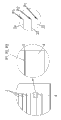
Fig. 6 illustrates the perspective schematic view of second embodiment of thin-layer solar module of the present invention.
Embodiment
At first see figures.1.and.2, at this thin-layer solar module of representing by sketch map and different sectional view explanation entirety by reference numeral 1.Being used for the sunlight opto-electronic conversion is that the thin-layer solar module 1 of electric energy is the embodiment of solar battery apparatus of the present invention.At this, thin-layer solar module 1 comprises a plurality of that be connected in series, integrated solar cells 2, and said solar cell 2 is embodiments of the solar cell of solar battery apparatus of the present invention.
Thin-layer solar module 1 has the structure corresponding to substrate arrangement, and promptly thin-layer solar module 1 has the substrate 4 of electric insulation and is applied to the layer structure 5 on this substrate by what thin layer was processed, and its middle level structure 5 is arranged on the first type surface 6 of light incident side of substrate 4.Substrate 4 for example is made up of the glass with relatively little light transmittance at this, wherein can adopt equably to have sufficient intensity and with respect to other insulating material of the inert nature of performed process steps.
Layer structure 5 comprises the dorsum electrode layer 7 on the first type surface 6 that is arranged on substrate 4, and this dorsum electrode layer can for example be made up of lighttight metal such as molybdenum (Mo) and for example be applied on the substrate 4 through cathodic sputtering.Dorsum electrode layer 7 for example has the bed thickness of about 1 μ m.In another embodiment, dorsum electrode layer also can be piled up by the layer of different single layers and form.The photoelectric activity absorbed layer 8 that deposition is made up of the semiconductor that mixes on dorsum electrode layer 7, this semi-conductive band gap preferably can the possible sunlights of component greatly of dampen out.Absorbed layer 8 for example is made up of the chalcopyrite semiconductor of p conducting, for example from Cu (InGa) (SSe)
2, the mixed two selenium copper indium (CuInSe of sodium (Na) especially
2) compound of the group that constitutes.Absorbed layer 8 for example has scope that is arranged in 1-5 μ m and the bed thickness that for example is approximately 2 μ m.Deposition resilient coating 9 on absorbed layer 8, this resilient coating 9 for example is made up of the cadmium sulfide (CdS) of individual layer and the intrinsic zinc oxide (i-ZnO) of individual layer at this, and this is not shown specifically in the accompanying drawings.Resilient coating 9 for example has the bed thickness littler than absorbed layer 8.Electrode layer 10 before on resilient coating 9, for example applying through vapor deposition.Before 10 pairs of the electrode layers ray in the spectral region sensitive for absorbed layer 8 be transparent (" Window layer "), have only very little decay with the sunlight that guarantees incident.The transparent preceding electrode layer 10 that generally can be called tco layer (TCO=Transparent Conductive Electrode, transparency conductive electrode) is based on the metal oxide that mixes, zinc oxide (AZO) for example the n conducting, that be doped with aluminium (Al).Through preceding electrode layer 10, form pn heterojunction (sequence that promptly has the different layers of opposite conducting type) with resilient coating 9 and absorbed layer 8.The bed thickness of preceding electrode layer 10 for example is about 800nm.
In order to protect environmental impact, on preceding electrode layer 10, apply the plastic layer of for example forming 11 by polyvinyl butyral resin (PVB) or ethylene vinyl acetate (EVA).In addition, use covering plate transparent concerning sunlight 12 confining bed structures 5, said covering plate for example is made up of the extremely white glass with little iron-holder.
In order to improve total module stress, the module faces of thin-layer solar module 1 is divided into a plurality of single solar cells 2, and these solar cells are connected to series circuit respectively in the first solar cell branch road 28 and the second solar cell branch road 29.For this purpose, adopting suitable structured techniques that writes such as laser and the for example mechanical treatment through molding or delineation to come to 5 structurings of layer structure.At this importantly, the as much as possible little and structured techniques that adopted of the loss of photoelectricity area is optionally for material to be removed.Such structuring all comprises 3 structuring steps with typical mode to each solar cell 3, and these structuring steps are used initialism P1, P2, P3 abbreviation.This will set forth under with reference to the situation of the left side view of Fig. 2 below in detail.
In the first structuring step P1, interrupt dorsum electrode layers 7 through producing ground floor ditch 13, wherein form the first back electrode fragment 14 and with respect to the second back electrode fragment 15 of its insulation.Ground floor ditch 13 preferably writes (for example by PRK or neodymium-YAG laser) through laser at this and perhaps forms through the mechanical treatment to dorsum electrode layer 7.Ground floor ditch 13 formed before applying absorbed layer 8 and when applying absorbed layer 8, is filled by the semi-conducting material of this layer.
In the second structuring step P2, two semiconductor layers, just absorbed layer 8 and resilient coating 9 interrupt through producing second layer ditch 16, wherein form first semiconductor fragment 17 and with respect to second semiconductor fragment 18 of its insulation.Second layer ditch 16 preferably writes (for example by PRK or neodymium-YAG laser) through laser at this and forms.Second layer ditch 16 forms before the electrode layer 10 before applying and before applying, is filled by the electric conducting material of this layer during electrode layer 10.
In the 3rd structuring step P3; Before electrode layer 10, resilient coating 9 and absorbed layer 8 interrupt through producing the 3rd layer of ditch 19, wherein except the fragment of the interruption of semiconductor layer, also form electrode fragment 20 before first and with respect to its insulation second before electrode fragment 21.The 3rd layer of ditch 19 preferably forms through mechanical treatment at this.The 3rd layer of ditch 19 before applying plastic layer 11, form and when applying plastic layer 11 by the filling insulating material of this layer.Can considering of replacement, the 3rd layer of ditch 19 only interrupts preceding electrode layer 10.
Thus; Through three structuring step P1; P2; P3 forms two solar cells that are connected in series 2, and wherein the first preceding electrode fragment 20 and the first back electrode fragment 14 form the preceding electrode and the back electrode of a solar cell 2, and the preceding electrode and the back electrode of the second preceding electrode fragment 21 and the second back electrode fragment, 15 another solar cells 2 of formation.At this, the preceding electrode of a solar cell 2 is connected with the back electrode of another solar cell 2 conduction.
At structuring step P1, P2, among the P3, layer ditch 13,16,19 forms along the structuring line, and said structuring line is corresponding to structuring step P1, P2, the title of P3 and be called as first, second and the 3rd structuring line 22-24.In Fig. 3, schematically show three structuring line 22-24; The vertical view in the cross section that illustrates thin-layer solar module 1 wherein; Middle illustrates corresponding to detailed fragment discernible zone, thin-layer solar module 1, and the vertical view that illustrates the single solar cell 2 that is used for description architecture line 22-24 on right side.
As shown in Figure 1; Thin-layer solar module 1 has structure rectangular in vertical view, wherein is divided into first module region 26 and second module region 27 of separating with first module region, 26 electricity with the layer structure 5 of corresponding manner rectangle through the regional ditch 25 that wherein layer structure 5 is scavenged into the centre of substrate 4 fully.Two module region 26,27 are of similar shape with size and on the first direction (x) that the long size through thin-layer solar module 1 or substrate 4 limits and are arranged side by side.At this, first direction (x) is with the plane of second direction (y) tensioning perpendicular to first direction, and this plane is parallel with the first type surface 6 of substrate 4.Can find out that regional ditch 25 extends along second direction (y) point-blank.
Two module region 26,27 have independent solar cell branch road respectively, wherein in first module region 26, constitute the first solar cell branch road 28 and in second module region 27, constitute the second solar cell branch road 29.At two solar cell branch roads 28; In 29, solar cell 2 is connected in series to same orientation respectively, and wherein each solar cell 2 can pass through the solar cell Symbol recognition; And solar cell branch road 28,29 can be through the solar cell Symbol recognition of logic connection.In Fig. 1, each solar cell branch road 28,29 for example comprises 11 solar cells 2, should be appreciated that wherein these solar cells can comprise the solar cell 2 of greater or lesser quantity respectively.Each solar cell branch road 28,29 can for example have for example 40 to 150, preferred 50 to 110, preferred especially 100 to 110 and preferred fully especially 104 and connect into solar cell 2 series circuit, same orientation.
Stripe-shaped solar cell 2 extends along first direction (x); And be provided with along second direction (y); Wherein adjacent solar cell 2 is separated from each other through (imagination) defiber 3 that extends along first direction (x), and said defiber 3 provides through the position of the 3rd layer of affiliated ditch 19.The structuring of passing through first to the 3rd structuring line 22-24 of solar cell 2 is carried out along first direction (x).Correspondingly, solar cell branch road 28,29 is connected in series along second direction (y) respectively, and the short size of said second direction and thin-layer solar module 1 or substrate 4 is corresponding.
Two solar cell branch roads 28,29 have antiparallel direction of passage, and wherein the first solar cell branch road 28 (y) pass through, and the second solar cell branch road 29 passes through along positive second direction (y) along negative second direction.Antiparallel solar cell branch road 28,29 is through three structuring step P1, and P2 sets forth below being manufactured on of P3 in detail.
In thin-layer solar module 1, constitute narrow fringe region 30,31 respectively in both sides along first direction (x) at least, said fringe region especially as the contact zone of solar cell branch road 28,29, wherein appears the corresponding electrode layer for this purpose.Connect contact 32 and in second module region 27, form the 3rd and connect contact 34 thereby in first module region 26 of first fringe region 30, form first, these two connect contact each other electricity separate.In contrast, in second fringe region 31, exceed two module region 26,27 ground formation indirect and touch 33.At this, contact 32-34 for example constitutes with the form of metal tape that especially can be made of aluminum.
At this; First connects contact 32 is connected with middle contact 34 conductions through the first solar cell branch road 28; Wherein corresponding with being electrically connected of the back electrode of the preceding electrode of the solar cell 2 of front and the solar cell 2 of back; First connects contact 32 is connected with the preceding electrode electricity of first solar cell 2, and the centre contacts 34 and is electrically connected with the back electrode of last solar cell 2.
In addition; Middle contact 34 is connected contact 33 conductions through the second solar cell branch road 29 and connects with second; Wherein with first module region 26 in be connected corresponding; Contact 34 is connected with the preceding electrodes conduct of first solar cell 2 in the middle of second, and second connect and contact 33 and conduct electricity with the back electrode of last solar cell 2 of the second solar cell branch road 29 and to be connected.
Electrically contacting 32-34 and for example can weld through welding, bonding or solder flux and make in two fringe regions 31,32 is preferably through the ultrasonic bonding manufacturing.According to the present invention, be set that the electrode layer separately and the metal tape that are used to connect weld according to the present invention, the welding of bonding or solder flux, and make continual and steady electrical connection.
The first connection contact 32 is connected contact 33 conduction connections through two solar cell branch roads 28,29 with second in thin-layer solar module 1 thus, and said solar cell branch road 28,29 is connected in series through centre contact 34.All solar cells 2 same orientation all in the solar cell branch road 28,29 that is connected in series.
In addition, the terminal box 35 common to two solar cell branch roads 28,29 is set in first fringe region 30, this terminal box is arranged on the back side of first type surface dorsad 6 of substrate 4 and is equipped with and is used to connect two equipment that connect contact 32,33.For example, two connect contact 32,33 through getting loose or stationary device is connected with terminal box 35.Terminal box 35 is used for thin-layer solar module 1 is connected with electric loading, the current transformer that does not for example illustrate in the drawings.
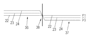
Set forth a kind of being used for when making thin-layer solar module 1 referring now to Fig. 4 A and 4B to layer structure 5 structurized methods.
In view of the above, the first structuring line 22 of the first structuring step P1 exceeds complete layer structure 5 ground and guides point-blank along first direction (x).Different therewith, two structuring lines 23,24 of all the other of structuring step P2, P3 have respectively along the lateral displacement of second direction (y) in two zones 36,37 corresponding to module region 26,27.Thereby; The second structuring line 23 layer structure 5 with first module region, 26 corresponding first areas 36 in go up to have with displacement in positive second direction (y) and be provided with the first structuring line 22; On the contrary, the second structuring line 23 layer structure 5 with second module region, 27 corresponding second areas 37 in (y) go up to have with displacement and be provided with in negative second direction with the first structuring line 22.On the other hand; The 3rd structuring line 24 upward has setting with displacement with the second structuring line 23 in positive second direction (y) in first area 36; On the contrary, the 3rd structuring line 24 (y) upward has setting with displacement with the second structuring line 23 in negative second direction in the second area 37 of layer structure 5.Preferably; The second and the 3rd structuring line 23 for this purpose; 24 is crossing with the first structuring line 22 in the 3rd zone 38 that is provided with in order to form regional ditch 25 respectively, wherein in first area 36, has the 3rd structuring line 24 that is provided with displacement in second area 37, along the negative second direction (y) and the second structuring line 23 setting with displacement to be arranged along the positive second direction (y) and the second structuring line 23.Thus; The spatial order of three structuring line 22-24 in first area 36 is opposite with the spatial order of three structuring line 22-24 in the second area 37 of layer structure 5; Wherein first, second is arranged side by side along positive second direction (y) with the 3rd structuring line in first area 36, and the 3rd, the second and first structuring line is arranged side by side along positive second direction (y) in second area 37 on the contrary.
In another step, regional ditch 25 constitutes in the 3rd zone 38, wherein for this purpose scavenger layer structure 5 up to substrate 4.Through forming regional ditch 25, form two mutual electric separate modules zones 26,27.Zone ditch 25 only forms in the 3rd zone 38 of layer structure 5, wherein has structuring line 23,24 and fragment first direction (x) diagonally extending.As already mentioned; Can pass through the second and the 3rd structuring line 23; 24 along the lateral displacement of second direction (y) with the putting upside down of the order of simple mode implementation structure line, this causes the direction of passage of solar cell 2 in two module region 25,26 on the contrary or antiparallel ground orientation.
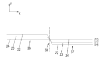
The modification to layer structure 5 structurized methods that is used in Fig. 5 A explanation replaces the first structuring line, 22 ground, and the second structuring line 23 of structuring step P2 exceeds complete layer structure 5 ground and guides point-blank along first direction (x).Different therewith, all the other two structuring lines 22,24 have respectively along the lateral displacement of second direction (y) in first and second zones 36,37.At this; The first structuring line 22 (y) has setting with displacement with the second structuring line 23 along negative second direction in the first area 36 of layer structure 5; On the contrary, the first structuring line 22 upward has setting with displacement with the second structuring line 23 in positive second direction (y) in the second area 37 of layer structure 5.On the other hand; The 3rd structuring line 24 has setting with displacement along the positive second direction (y) and the second structuring line 23 in first area 36; On the contrary, the 3rd structuring line 24 (y) upward has setting with displacement with the second structuring line 23 in negative second direction in the second area 37 of layer structure 5.Preferably, the first and the 3rd structuring line 22,24 intersects with the second structuring line 22 in the 3rd zone 38 respectively for this purpose.Thus; The spatial order of three structuring line 22-24 in first area 36 is opposite with the spatial order of three structuring line 22-24 in the second area 37 of layer structure 5; Wherein first, second is arranged side by side along positive second direction (y) with the 3rd structuring line in first area 36, and the 3rd, the second and first structuring line is arranged side by side along positive second direction (y) in second area 37 on the contrary.
In the modification to layer structure 5 structurized methods that is used for of Fig. 5 B explanation, the 3rd structuring line 24 exceeds complete layer structure 5 ground and guides point-blank along first direction (x).Different therewith, all the other two structuring lines 22,23 have respectively along the lateral displacement of second direction (y) in two zones 36,37.At this; The second structuring line 23 has setting with displacement along positive second direction (y) and the 3rd structuring line 24 in first area 36; On the contrary, the second structuring line 23 (y) upward has setting with displacement with the 3rd structuring line 24 in negative second direction in second area 37.On the other hand; The first structuring line 22 upward has setting with displacement with the second structuring line 23 in positive second direction (y) in first area 36; On the contrary, the first structuring line 22 (y) upward has setting with displacement with the second structuring line 23 in negative second direction in second area 37.Preferably, the first and second structuring lines 22,23 intersect with the 3rd structuring line 24 in the 3rd zone 38 respectively for this purpose.Thus; The spatial order of three structuring line 22-24 in first area 36 is opposite with the spatial order of three structuring line 22-24 in the second area 37 of layer structure 5; Wherein first, second is arranged side by side along positive second direction (y) with the 3rd structuring line in first area 36, and the 3rd, the second and first structuring line is arranged side by side along positive second direction (y) in second area 37 on the contrary.
Be used for different modification to layer structure 5 structurized methods and can be being used to making the part of the method for thin-layer solar module 1.
In first modification of the illustrative methods that is used for making thin-layer solar module 1, adopt Fig. 4 A to be used for layer structure 5 structurized first modification with 4B explains.Carry out following steps continuously at this:
-utilize dorsum electrode layer 7 (molybdenum) to substrate 4 coatings;
-be used to make the structuring step P1 of back electrode fragment 14,15 of the insulation of dorsum electrode layer 7, wherein the first structuring line 22 has the extension of straight line;
Absorbed layer 8 (the Cu-Ga-In-(Se/S): Na) that-deposition or formation are mixed;
The ground floor (CdS) of-deposition resilient coating 9; The second layer (i-ZnO) of deposition resilient coating 9;
-be used between the preceding electrode fragment of adjacent solar cell and back electrode fragment, making the structuring step P2 that is electrically connected, wherein the second structuring line 23 has lateral displacement corresponding to Fig. 4 A;
The preceding electrode layer 10 (ZnO:A) of-dopant deposition
-be used for adjacent solar cell 2 structurized structuring step P3, wherein the 3rd structuring line 24 has lateral displacement corresponding to Fig. 4 A, and till layer structure 5 be removed to the back side, is used in two fringe regions 30,31, constituting contact zones;
-except the contact zone, remove two fringe regions 30,31, and also remove other fringe region that is not shown specifically in case of necessity along substrate 4, and till regional ditch 25 is removed to substrate 4;
-contact contacts 32-34 (Al metal stripe) with being connected in the middle of making;
-layer structure 5 and plastic layer 11 are carried out lamination;
-installation connection box 35, and terminal box 35 is connected contact 32,33 connects with two.
In second modification of the illustrative methods that is used for making thin-layer solar module 1, adopt second modification of explaining among Fig. 5 A that is used for to layer structure 5 structurized methods.Carry out following steps continuously at this:
-utilize dorsum electrode layer 7 (molybdenum) to substrate 4 coatings;
-be used to make the structuring step P1 of back electrode fragment 14,15 of the insulation of dorsum electrode layer 7, wherein the first structuring line 22 has lateral displacement corresponding to Fig. 5 A ground;
Absorbed layer 8 (the Cu-Ga-In-(Se/S): Na) that-deposition or formation are mixed;
The ground floor (CdS) of-deposition resilient coating 9;
The second layer (i-ZnO) of-deposition resilient coating 9;
-be used between the preceding electrode fragment of adjacent solar cell and back electrode fragment, making the structuring step P2 that is electrically connected, wherein the second structuring line 23 has straight-line extension;
The preceding electrode layer 10 (ZnO:A) of-dopant deposition
-be used for adjacent solar cell 2 structurized structuring step P3, wherein the 3rd structuring line 24 has lateral displacement corresponding to Fig. 5 A;
-remove two fringe regions 30,31, and also remove in case of necessity along other fringe region that is not shown specifically of the shorter size of substrate (4), and remove regional ditch 25;
-contact contacts 32-34 (Al metal stripe) with being connected in the middle of making;
-layer structure 5 and plastic layer 11 are carried out lamination;
-installation connection box 35, and terminal box 35 is connected contact 32,33 connects with two.
In the 3rd modification of the illustrative methods that is used for making thin-layer solar module 1, adopt second modification of explaining among Fig. 5 B that is used for to layer structure 5 structurized methods.Carry out following steps continuously at this:
-utilize dorsum electrode layer 7 (molybdenum) to substrate 4 coatings;
-be used to make the structuring step P1 of back electrode fragment 14,15 of the insulation of dorsum electrode layer 7, wherein the first structuring line 22 has lateral displacement corresponding to Fig. 5 B ground;
Absorbed layer 8 (the Cu-Ga-In-(Se/S): Na) that-deposition or formation are mixed;
The ground floor (CdS) of-deposition resilient coating 9;
The second layer (i-ZnO) of-deposition resilient coating 9;
-be used between the preceding electrode fragment of adjacent solar cell and back electrode fragment, making the structuring step P2 that is electrically connected, wherein the second structuring line 23 has lateral displacement corresponding to Fig. 5 B ground;
The preceding electrode layer 10 (ZnO:A) of-dopant deposition
-be used for adjacent solar cell 2 structurized structuring step P3, wherein the 3rd structuring line 24 has straight-line extension, and till layer structure 5 be removed to the back side, is used in two fringe regions 30,31, constituting contact zones;
-except the contact zone, remove two fringe regions 30,31, and also remove other fringe region that is not shown specifically in case of necessity along substrate 4, and till regional ditch 25 is removed to substrate 4 always;
-contact contacts 32-34 (Al metal stripe) with being connected in the middle of making;
-layer structure 5 and plastic layer 11 are carried out lamination;
-installation connection box 35 is connected contact 32,33 with terminal box 35 and connects with two.
The different modification that are used to make thin-layer solar module 1 make can through to 5 structurings of layer structure the time suitably guide structure line 22-24 come to produce simply antiparallel solar cell branch road 28,29.Advantageously, except the contact zone, regional ditch 25 and two fringe regions 30,31 are jointly, preferably side by side be removed to till the substrate.
The special benefits of thin-layer solar module 1 is; Only need a unique terminal box 35 to connect contact 32 with two; 33 connect, can reduce thus manufacturing cost and since especially the susceptibility-to-corrosion of the terminal box 35 that causes of the invasion through moisture improve the long-time stability and the reliability of thin-layer solar module 1.Solar cell branch road 28 through two antiparallel orientations; 29; Two connect contact 32,33 and are arranged on the same side of thin-layer solar module 1, thus can abandon taking a lot of trouble in an advantageous manner, be used for connecting contact 32 with two; 33 cables that are electrically connected with common terminal box 35 lay, and this cable is laid in and also possibly causes the photoelectric activity zone desirably not hidden in the substrate arrangement.Connecting contact 32,33 being connected in series through two by two solar cell branch roads 28,29---said solar cell branch road 28,29 itself has been realized the configuration of U-shaped through centre contact 34 connection that is one another in series.
The width of zone ditch 25 especially depends on the puncture voltage of two module region 26,27 and for example is in from 1 to 10mm scope.Zone ditch 25 can use the material of electric insulation to fill, to improve breakdown strength.On manufacturing technology, the width of regional ditch 25 depends on the writing speed of structuring line 22-24.The module region 26,27 that thin-layer solar module 1 is divided into two same size causes doubling of reducing by half of solar cell electric current and solar array voltage.Thus; The solar cell electric current is the function along the width of the solar cell 2 of first direction (x) measurement; This width for example is in 1 to 11mm the scope; Preferably be in 2 to 8mm the scope, and especially equal about 5.5mm, to obtain current/voltage characteristic favourable concerning technical application.
With reference to Fig. 6, second embodiment of the thin-layer solar module of the present invention 1 of entirety by reference numeral 101 expression is described now, wherein the difference with first embodiment is only described for fear of unnecessary repeating, other part with reference to above the enforcement carried out.
In view of the above; The module faces of thin-layer solar module 101 is divided into a plurality of single solar cells 102, and these solar cells are interconnected to series circuit respectively in the first solar cell branch road 103, the second solar cell branch road 104, the 3rd solar cell branch road 105 and the 4th solar cell branch road 106.At this; The thin-layer solar module 101 that in vertical view, has a rectangular configuration is divided into first module region 110, second module region 111, three module zone 112 and four module zone 113; Wherein first module region 110 is separated through first area ditch 107 is electric each other with second module region 111; Second module region 111 is separated through second area ditch 108 is electric each other with three module regional 112, and separate through the 3rd regional ditch 109 mutual electricity with four module zone 113 in three module zone 112.Module region 110-113 is of similar shape and size, and on the first direction (x) that the long size through thin-layer solar module 101 limits, in series is arranged side by side.Zone ditch 107-109 extends along the second direction vertical with first direction (y) respectively point-blank.
Each module region 110-113 has independent solar cell branch road, wherein in first module region 110, constitutes the first solar cell branch road 103, in second module region 111, constitutes the second solar cell branch road 104, in three module zone 112, constitutes the 3rd solar cell branch road 105 and in four module zone 113, constitute the 4th solar cell branch road 106.In each solar cell branch road 103-106, solar cell 102 is connected in series to same orientation respectively.The solar cell 102 of stripe-shaped extends along first direction (x), and is provided with along second direction (y), and wherein adjacent solar cell 103 is separated from each other through (imagination) defiber 114 that extends along first direction (x).Solar cell 102 carries out along first direction (x) through the structuring of first to the 3rd structuring step P1-P3.Correspondingly, solar cell branch road 103-106 is connected in series along second direction (y) respectively, and the short size of this second direction and thin-layer solar module 101 is corresponding.In thin-layer solar module 101; Adjacent solar cell branch road 103-106 has antiparallel direction of passage respectively; Wherein the first solar cell branch road 103 (y) passes through along negative second direction; The second solar cell branch road 29 passes through along positive second direction (y), and the 3rd solar cell branch road 105 (y) pass through, and the 4th solar cell branch road 106 passes through along positive second direction (y) along negative second direction.
In thin-layer solar module 101, constitute narrow fringe region 115,116 respectively along first direction (x) both sides, they especially as the contact zone of solar cell branch road 103-106, wherein appear electrode layer separately for this purpose.Thereby in first module region 110 of first fringe region 115, form first connect contact 117 (promptly exceed second with three module regional 111; 112 second in the middle of contact 119) and in four module zone 113, form second and connect contact 121, these two connect contact respectively each other electricity separate.In contrast, in second fringe region 116, exceed first and second module region 110; Contact 118 in the middle of 111 ground form first; And exceed third and fourth module region, 112,113 ground and form that contact is electric each other in the middle of the contact 120, said first and the 3rd in the middle of the 3rd separates.117-121 for example constitutes with the form of metal tape that especially can be made of aluminum in this contact.At this; First connects contact 117 is connected through 118 conductions of contact in the middle of the first solar cell branch road 103 and first; Contact 118 is connected through 119 conductions of contact in the middle of the second solar cell branch road 104 and second in the middle of first; Contact 119 is connected through 120 conductions of contact in the middle of the 3rd solar cell branch road 105 and the 3rd in the middle of second, and contact 120 is connected with second through the 4th solar cell branch road 106 and contacts 121 and conduct electricity connection in the middle of the 3rd.
In thin-layer solar module 101, first connects contact 117 is connected contact 121 conduction connections through four solar cell branch road 103-106 that are connected in series with second thus.In the solar cell branch road 103-106 that is connected in series, all solar cell 102 same orientation.
First terminal box 122 that is connected contact 117 connections with first is set in first module region 110 of this external first fringe region 115, and this first terminal box is arranged on the back side of thin-layer solar module 101 and is equipped with the equipment that is used to connect the first connection contact 117.In addition; In the four module of first fringe region 115 zone 113, be provided with and be connected second terminal box 123 that contact 121 connects with second, this second terminal box is arranged on the back side of thin-layer solar module 101 equally and is equipped with and is used to connect second connection and contacts 121 equipment.Two terminal boxes 122,123 are used for thin-layer solar module 101 is electrically connected with electric loading (for example current transformer).
Replacement, can also in this configuration, will connect contact 117 and 121 and also in terminal box 122,123, connect.
The manufacturing of antiparallel solar cell branch road 103-106 can be corresponding to by Fig. 4 A; 4B; The lateral displacement of the structuring line that 5A and 5B set forth carries out in three structuring step P1-P3; Wherein (y) the solar cell branch road direction put upside down to along positive second direction (y) orientation of the solar cell branch road direction of orientation realizes through the straight-line extension of structuring line and the lateral displacement of two other structuring lines illustrated in the accompanying drawings, and is put upside down to (y) the solar cell branch road direction of orientation realizes through the lateral displacement of mirror-inverted with respect to the structuring line of straight line of two other structuring lines along negative second direction along the solar cell branch road direction of positive second direction (y) orientation along negative second direction.Thin-layer solar module 101 shown in Figure 6 can be accomplished through the modification of the top manufacturing approach that illustrates, and wherein uses such structural method, makes through this structural method to produce antiparallel solar cell branch road 103-106 simply.Advantageously, regional ditch 107-109 and two fringe regions 115,116 are jointly, preferably side by side be removed.
The special benefits of thin-layer solar module 101 is; Each unique terminal box 122 of needs concerning solar cell branch road 103-106 to antiparallel orientations; 123 connect contact 117; 121, manufacturing cost be can reduce thus and the long-time stability and the reliability of thin-layer solar module 101 improved.Be connected in series through connecting contact 117,121 by 4 solar cell branch road 103-106 that itself are connected in series each other through centre contact 118-120 with two, realize the configuration that the U by a plurality of connections forms, the feasible cable that can abandon taking a lot of trouble of this configuration lays.Through quantity and the size that module region 110-113 is set, the quantity of the U that especially is connected in series can influence the current/voltage characteristic of thin-layer solar module 101 targetedly.Though, should be appreciated that the module region that greater or lesser quantity can be set at the thin-layer solar module that has four module region 110-113 shown in Fig. 6 101.At this preferably, have the module region of even number, wherein adjacent solar cell branch road has antiparallel direction of passage.
The invention provides a kind of thin-layer solar module, it can in industry is produced continuously, make with low costly and its long-time stability and fastness with respect to conventional thin-layer solar module is improved.Can influence the current/voltage characteristic of thin-layer solar module according to the mode of expectation targetedly.
Reference numerals list
1 thin-layer solar module
2 solar cells
3 defibers
4 substrates
5 layers of structure
6 first type surfaces
7 dorsum electrode layers
8 absorbed layers
9 resilient coatings
Electrode layer before 10
11 plastic layers
12 overlays
13 ground floor ditches
14 first back electrode fragments
15 second back electrode fragments
16 second layer ditches
17 first semiconductor fragment
18 second semiconductor fragment
19 the 3rd layers of ditch
Electrode fragment before 20 first
Electrode fragment before 21 second
22 first structuring lines
23 second structuring lines
24 the 3rd structuring lines
25 regional ditches
26 first module region
27 second module region
28 first solar cell branch roads
29 second solar cell branch roads
30 first fringe regions
31 second fringe regions
32 first connect contact
33 second connect contact
Contact in the middle of 34
35 terminal boxes
36 first areas
37 second areas
38 the 3rd zones
101 thin-layer solar modules
102 solar cells
103 first solar cell branch roads
104 second solar cell branch roads
105 the 3rd solar cell branch roads
106 the 4th solar cell branch roads
107 first area ditches
108 second area ditches
109 the 3rd regional ditches
110 first module region
111 second module region
112 three modules zone
113 four modules zone
114 defibers
115 first fringe regions
116 second fringe regions
117 first connect contact
Contact in the middle of 118 first
Contact in the middle of 119 second
Contact in the middle of 120 the 3rd
121 second connect contact
122 first terminal boxes
123 second terminal boxes
Claims (15)
1. solar battery apparatus (1,101), in particular for thin-layer solar module, this solar battery apparatus comprises substrate (4); On this substrate, apply the layer structure (5) with a plurality of layers (7-10), wherein this layer structure (5) is divided into a plurality of different zones (26,27; 110-113), (25,107-109) electricity separates the one or more regional ditches of these zone passages each other; Wherein in each zone (26,27, all constitute the solar cell (2 that comprises a plurality of same orientation that are connected in series in 110-113); Solar cell branch road 102) (28,29,103-106).
2. solar battery apparatus according to claim 1 (1,101), wherein the solar cell branch road (28,29,103-106) through contact in the middle of one or more (34,118-120) be connected in series.
3. according to the described solar battery apparatus (1 in one of claim 1 or 2; 101); Its middle level structure (5) has first electrode layer (10), the second electrode lay (7) and is arranged on two electrode layers (7; 10) semiconductor layer between (8) forms the pn knot through these layers, and wherein semiconductor layer (8) is formed by chalcopyrite compound, cadmium telluride and/or silicon.
4. according to the described solar battery apparatus of one of claim 1 to 3 (1,101), have the first connection contact (32,117) and be connected contact (33 with second; 121), said first connect contact is connected with second contact through the solar cell branch road (28,29,103-106) mutual electrical connection; Wherein the solar cell branch road (28,29,103-106) through contact in the middle of one or more (34,118-120) be connected in series; Have at least one and connect shell (35,122,123), two connect contact (32; 33,117,121) connect at least one connection shell at this.
5. solar battery apparatus according to claim 4 (1,101), wherein:
-layer structure is divided into two through the mutual electric separate areas of regional ditch (25) (26,27),
-the first connects contact (32) is connected contact (33) through two solar cell branch roads (28,29) electrical connection each other with second, wherein two solar cell branch roads (28,29) are connected in series through middle contact (34),
-two connect contact (32,33) and are connected to common connection shell (35).
6. solar battery apparatus according to claim 4 (101), wherein:
-layer structure is divided into four zones (110-113), and these three regional ditches of four zone passages (107-109) electricity each other separate,
-the first connection contact (117) is connected contact (121) and is electrically connected each other through 4 solar cell branch roads (103-106) with second, wherein 4 solar cell branch roads (103-106) are connected in series through 3 middle contacts (118-120),
-two connect contact (117,121) and are connected respectively to independent connection shell (122,123).
7. according to the described solar battery apparatus of one of claim 1 to 6 (1,101), wherein solar cell (2,102) constitutes stripe-shaped respectively.
8. according to the described solar battery apparatus of one of claim 1 to 7 (1,101), (32-34 is 117-121) respectively with the form formation of contact zones wherein to connect contact and middle the contact.
9. according to the described solar battery apparatus of one of claim 1 to 8 (1,101), wherein at least one regional ditch (25,107-109) have with its extension vertical survey, be in 0.5 to the 10mm scope, the width in 1 to the 3mm scope especially.
10. according to the described solar battery apparatus of one of claim 1 to 9 (1,101), wherein at least one regional ditch (25,107-109) filled by the material of electric insulation.
11. thin-layer solar module (1,101), it constitutes with the form according to the solar battery apparatus of one of claim 1 to 10.
12. thin-layer solar module (1 according to claim 11; 101); Wherein first electrode layer (10) is that transparent preceding electrode layer and the second electrode lay (7) is dorsum electrode layer, and wherein substrate (4) is arranged on a side of preceding electrode layer dorsad of dorsum electrode layer.
13. be used for to thin-layer solar module (1; 101) layer structure (5) carried out structurized method; This layer structure (5) comprises first electrode layer (10), the second electrode lay (7) and is arranged on the semiconductor layer (8) between two electrode layers (7,10) that this method may further comprise the steps:
-in the second electrode lay (7), producing the first structuring line (22), the second electrode lay (7) is divided into the second layer fragment (14,15) that mutual electricity separates thus,
-produce the second structuring line (23), be used for first electrode layer (10) and the second electrode lay (7) electrical connection are connected in series solar cell being used for,
-in first electrode layer (10), producing the 3rd structuring line (24), first electrode layer (10) is divided into the ground floor fragment (20,21) that mutual electricity separates thus,
A structuring line of wherein selecting from first to the 3rd structuring line (22-24) is directed to; Make this structuring line have at least two mutual electric separate areas (26 of surpassing; 27; Straight-line extension 110-113), and all the other two structuring lines and this structuring line have displacement each other makes the reversed in order of these structuring lines (22-24).
14. method according to claim 13; A structuring line of wherein selecting from first to the 3rd structuring line (22-24) is directed to; Make this structuring line have at least two mutual electric separate areas (26 of surpassing; 27, straight-line extension 110-113), and all the other two structuring lines and this structuring line intersect for making the reversed in order of these structuring lines (22-24).
15. be used to make the method for thin-layer solar module (1,101), this method may further comprise the steps:
-layer structure (5) is applied on the substrate (4), wherein this layer structure (5) has at least the first electrode layer (10), the second electrode lay (7) and is arranged on the semiconductor layer (8) between two electrode layers (7,10), forms the pn knot through these layers,
-through method said layer structure (5) carried out structuring according to claim 14; Make to produce a plurality of respectively by the solar cell (2 of a plurality of that be connected in series, same orientation; The solar cell branch road of 102) forming (28,29,103-106); Solar cell branch road wherein adjacent one another are especially can have antiparallel direction of passage
-with one or more regional ditches (25,107-109) be set in layer structure (5), make the disparate modules zone comprise independent solar cell branch road respectively (26,27,110-113) electricity separates each other,
-through form one or more in the middle of contact (34,118-120) with the solar cell branch road (28,29,103-106) be connected in series,
-form first and connect contact (32,117) and is connected contact (33,121) with second, said first connect contact is connected with second contact and the solar cell branch road (28,29,103-106) conduct electricity connection,
-connect two connection contacts of connection (32,33,117,121) in the shell (35,122,123) at least one.
Applications Claiming Priority (3)
| Application Number | Priority Date | Filing Date | Title |
|---|---|---|---|
| EP10152086.4 | 2010-01-29 | ||
| EP10152086A EP2352171A1 (en) | 2010-01-29 | 2010-01-29 | Solar cell configuration and thin film solar module and method for producing same |
| PCT/EP2011/051133 WO2011092239A1 (en) | 2010-01-29 | 2011-01-27 | Solar cell array and thin-film solar module and production method therefor |
Publications (1)
| Publication Number | Publication Date |
|---|---|
| CN102714231A true CN102714231A (en) | 2012-10-03 |
Family
ID=43332661
Family Applications (1)
| Application Number | Title | Priority Date | Filing Date |
|---|---|---|---|
| CN2011800076202A Pending CN102714231A (en) | 2010-01-29 | 2011-01-27 | Solar cell array and thin-film solar module and production method therefor |
Country Status (8)
| Country | Link |
|---|---|
| US (1) | US20120285512A1 (en) |
| EP (2) | EP2352171A1 (en) |
| JP (1) | JP2013518424A (en) |
| KR (1) | KR101502208B1 (en) |
| CN (1) | CN102714231A (en) |
| EA (1) | EA201290719A1 (en) |
| WO (1) | WO2011092239A1 (en) |
| ZA (1) | ZA201205387B (en) |
Cited By (1)
| Publication number | Priority date | Publication date | Assignee | Title |
|---|---|---|---|---|
| CN105103293A (en) * | 2013-03-15 | 2015-11-25 | 尼斯迪格瑞科技环球公司 | Photovoltaic module having printed PV cells connected in series by printed conductors |
Families Citing this family (2)
| Publication number | Priority date | Publication date | Assignee | Title |
|---|---|---|---|---|
| CN110335902A (en) * | 2017-03-09 | 2019-10-15 | 伟创力有限公司 | Stacked tile type array solar cells and manufacture include the method for the solar components of stacked tile type array solar cells |
| KR101842393B1 (en) * | 2017-05-10 | 2018-03-26 | 한양대학교 산학협력단 | PN junction light modulator and method of fabrication of the same |
Citations (5)
| Publication number | Priority date | Publication date | Assignee | Title |
|---|---|---|---|---|
| DE19934560A1 (en) * | 1999-07-22 | 2001-02-01 | Zsw | Photovoltaic module has integrated, series cells, protective trench in lateral region between rear contacts of two adjacent cells before formation of structuring lines, filled with contact material |
| US6870087B1 (en) * | 2001-09-14 | 2005-03-22 | Patrick Gallagher | Assembly method and apparatus for photovoltaic module |
| CN101421846A (en) * | 2006-04-13 | 2009-04-29 | 壳牌可再生能源有限公司 | Solar module |
| US20090126773A1 (en) * | 2005-02-16 | 2009-05-21 | Akira Shimizu | Solar Cell and Fabrication Method Thereof |
| CN102549762A (en) * | 2009-09-30 | 2012-07-04 | Lg伊诺特有限公司 | Photovoltaic power generating apparatus |
Family Cites Families (16)
| Publication number | Priority date | Publication date | Assignee | Title |
|---|---|---|---|---|
| JPH0660155U (en) * | 1993-01-12 | 1994-08-19 | 鐘淵化学工業株式会社 | Integrated solar cell module |
| DE4324318C1 (en) | 1993-07-20 | 1995-01-12 | Siemens Ag | Method for series connection of an integrated thin-film solar cell arrangement |
| JP2001036105A (en) * | 1999-07-16 | 2001-02-09 | Sanyo Electric Co Ltd | Solar battery module |
| EP1069624A3 (en) * | 1999-07-16 | 2007-03-07 | SANYO ELECTRIC Co., Ltd. | Solar cell module |
| JP2001036104A (en) * | 1999-07-16 | 2001-02-09 | Sanyo Electric Co Ltd | Solar battery module |
| JP2005277113A (en) * | 2004-03-25 | 2005-10-06 | Sanyo Electric Co Ltd | Stacked solar cell module |
| JP2005277187A (en) * | 2004-03-25 | 2005-10-06 | Sharp Corp | Solar battery module |
| JP2006332353A (en) * | 2005-05-26 | 2006-12-07 | Fuji Electric Holdings Co Ltd | Solar cell module |
| WO2007118814A2 (en) * | 2006-04-13 | 2007-10-25 | Shell Erneuerbare Energien Gmbh | Solar module |
| JP4290747B2 (en) * | 2006-06-23 | 2009-07-08 | シャープ株式会社 | Photoelectric conversion element and photoelectric conversion element with interconnector |
| DE102006057454A1 (en) * | 2006-12-06 | 2008-06-26 | Schott Solar Gmbh | Photovoltaic module |
| JP4819004B2 (en) * | 2007-08-10 | 2011-11-16 | シャープ株式会社 | Solar cell array and solar cell module |
| JP2009088175A (en) * | 2007-09-28 | 2009-04-23 | Sharp Corp | Thin film solar battery module and its manufacturing method |
| US20100126559A1 (en) * | 2008-11-26 | 2010-05-27 | Applied Materials, Inc. | Semi-Transparent Thin-Film Photovoltaic Modules and Methods of Manufacture |
| JP4758496B2 (en) * | 2009-05-15 | 2011-08-31 | シャープ株式会社 | Thin film solar cell module |
| AU2010273709B2 (en) * | 2009-06-29 | 2015-08-20 | Nanoh2O, Inc. | Improved hybrid TFC RO membranes with nitrogen additives |
-
2010
- 2010-01-29 EP EP10152086A patent/EP2352171A1/en not_active Withdrawn
-
2011
- 2011-01-27 EA EA201290719A patent/EA201290719A1/en unknown
- 2011-01-27 CN CN2011800076202A patent/CN102714231A/en active Pending
- 2011-01-27 EP EP11701138A patent/EP2529407A1/en not_active Withdrawn
- 2011-01-27 WO PCT/EP2011/051133 patent/WO2011092239A1/en active Application Filing
- 2011-01-27 US US13/519,578 patent/US20120285512A1/en not_active Abandoned
- 2011-01-27 KR KR1020127019905A patent/KR101502208B1/en not_active IP Right Cessation
- 2011-01-27 JP JP2012550440A patent/JP2013518424A/en active Pending
-
2012
- 2012-07-18 ZA ZA2012/05387A patent/ZA201205387B/en unknown
Patent Citations (5)
| Publication number | Priority date | Publication date | Assignee | Title |
|---|---|---|---|---|
| DE19934560A1 (en) * | 1999-07-22 | 2001-02-01 | Zsw | Photovoltaic module has integrated, series cells, protective trench in lateral region between rear contacts of two adjacent cells before formation of structuring lines, filled with contact material |
| US6870087B1 (en) * | 2001-09-14 | 2005-03-22 | Patrick Gallagher | Assembly method and apparatus for photovoltaic module |
| US20090126773A1 (en) * | 2005-02-16 | 2009-05-21 | Akira Shimizu | Solar Cell and Fabrication Method Thereof |
| CN101421846A (en) * | 2006-04-13 | 2009-04-29 | 壳牌可再生能源有限公司 | Solar module |
| CN102549762A (en) * | 2009-09-30 | 2012-07-04 | Lg伊诺特有限公司 | Photovoltaic power generating apparatus |
Cited By (2)
| Publication number | Priority date | Publication date | Assignee | Title |
|---|---|---|---|---|
| CN105103293A (en) * | 2013-03-15 | 2015-11-25 | 尼斯迪格瑞科技环球公司 | Photovoltaic module having printed PV cells connected in series by printed conductors |
| US10020417B2 (en) | 2013-03-15 | 2018-07-10 | Printed Energy Pty Ltd | Photovoltaic module having printed PV cells connected in series by printed conductors |
Also Published As
| Publication number | Publication date |
|---|---|
| WO2011092239A1 (en) | 2011-08-04 |
| KR101502208B1 (en) | 2015-03-12 |
| EP2352171A1 (en) | 2011-08-03 |
| KR20120128616A (en) | 2012-11-27 |
| JP2013518424A (en) | 2013-05-20 |
| EA201290719A1 (en) | 2013-01-30 |
| US20120285512A1 (en) | 2012-11-15 |
| EP2529407A1 (en) | 2012-12-05 |
| ZA201205387B (en) | 2013-03-27 |
Similar Documents
| Publication | Publication Date | Title |
|---|---|---|
| US20120325282A1 (en) | Solar cells with grid wire interconnections | |
| KR20140003691A (en) | Solar cell module and ribbon assembly | |
| US11538950B2 (en) | Solar cell panel | |
| CN110313072B (en) | Partially translucent photovoltaic module and method for manufacturing | |
| US20110108107A1 (en) | Thin-Film Solar Battery Module and Method of Manufacturing the Same | |
| KR101440896B1 (en) | Thin film solar cell module and manufacturing method thereof | |
| CN109494266A (en) | Solar panel | |
| US20120031458A1 (en) | Solar cell module provided with an edge space | |
| KR20140095658A (en) | Solar cell | |
| CN102194900A (en) | Solar cell and method for manufacturing the same | |
| CN102714231A (en) | Solar cell array and thin-film solar module and production method therefor | |
| CN111247643B (en) | Photoelectric conversion module and method for manufacturing photoelectric conversion module | |
| KR101550927B1 (en) | Solar cell and method of fabircating the same | |
| KR101338610B1 (en) | Solar cell apparatus and method of fabricating the same | |
| CN103890959A (en) | Solar module with ribbon cable, and a method for the manufacture of same | |
| KR101154663B1 (en) | Solar cell apparatus | |
| EP2528106A1 (en) | Photovoltaic power generation device and manufacturing method thereof | |
| KR102084854B1 (en) | solar cell string and manufacturing method thereof | |
| KR102000063B1 (en) | Solar cell module | |
| CN111247642B (en) | Photoelectric conversion module and method for manufacturing photoelectric conversion module | |
| KR101349429B1 (en) | Photovoltaic apparatus | |
| KR102298447B1 (en) | Solar cell module | |
| EP2450968B1 (en) | Solar photovoltaic device | |
| US20130312821A1 (en) | Solar cell | |
| EP3803985B1 (en) | Solar modul with an enlarged aperture area |
Legal Events
| Date | Code | Title | Description |
|---|---|---|---|
| C06 | Publication | ||
| PB01 | Publication | ||
| C10 | Entry into substantive examination | ||
| SE01 | Entry into force of request for substantive examination | ||
| C02 | Deemed withdrawal of patent application after publication (patent law 2001) | ||
| WD01 | Invention patent application deemed withdrawn after publication |
Application publication date: 20121003 |