CN102712455B - Kit of parts for a module having a nozzle boot and a fuel dispensing unit having a nozzle module assembled with such a kit of parts - Google Patents
Kit of parts for a module having a nozzle boot and a fuel dispensing unit having a nozzle module assembled with such a kit of parts Download PDFInfo
- Publication number
- CN102712455B CN102712455B CN200980162968.1A CN200980162968A CN102712455B CN 102712455 B CN102712455 B CN 102712455B CN 200980162968 A CN200980162968 A CN 200980162968A CN 102712455 B CN102712455 B CN 102712455B
- Authority
- CN
- China
- Prior art keywords
- nozzle
- module
- chevron
- external member
- nozzle module
- Prior art date
- Legal status (The legal status is an assumption and is not a legal conclusion. Google has not performed a legal analysis and makes no representation as to the accuracy of the status listed.)
- Expired - Fee Related
Links
Images
Classifications
-
- B—PERFORMING OPERATIONS; TRANSPORTING
- B67—OPENING, CLOSING OR CLEANING BOTTLES, JARS OR SIMILAR CONTAINERS; LIQUID HANDLING
- B67D—DISPENSING, DELIVERING OR TRANSFERRING LIQUIDS, NOT OTHERWISE PROVIDED FOR
- B67D7/00—Apparatus or devices for transferring liquids from bulk storage containers or reservoirs into vehicles or into portable containers, e.g. for retail sale purposes
- B67D7/06—Details or accessories
- B67D7/84—Casings, cabinets or frameworks; Trolleys or like movable supports
-
- B—PERFORMING OPERATIONS; TRANSPORTING
- B67—OPENING, CLOSING OR CLEANING BOTTLES, JARS OR SIMILAR CONTAINERS; LIQUID HANDLING
- B67D—DISPENSING, DELIVERING OR TRANSFERRING LIQUIDS, NOT OTHERWISE PROVIDED FOR
- B67D7/00—Apparatus or devices for transferring liquids from bulk storage containers or reservoirs into vehicles or into portable containers, e.g. for retail sale purposes
- B67D7/04—Apparatus or devices for transferring liquids from bulk storage containers or reservoirs into vehicles or into portable containers, e.g. for retail sale purposes for transferring fuels, lubricants or mixed fuels and lubricants
-
- B—PERFORMING OPERATIONS; TRANSPORTING
- B67—OPENING, CLOSING OR CLEANING BOTTLES, JARS OR SIMILAR CONTAINERS; LIQUID HANDLING
- B67D—DISPENSING, DELIVERING OR TRANSFERRING LIQUIDS, NOT OTHERWISE PROVIDED FOR
- B67D7/00—Apparatus or devices for transferring liquids from bulk storage containers or reservoirs into vehicles or into portable containers, e.g. for retail sale purposes
- B67D7/06—Details or accessories
- B67D7/42—Filling nozzles
Abstract
This invention relates to a kit of parts (1) of a fuel dispenser, comprising top plates (2), gable cover plates (3), gable structures each comprising a nozzle boot, side cover plates, and side structures (4) each comprising a nozzle boot (5), which kit of parts (1) is suitable for assembling a nozzle module (8) according to any one of three configurations. The invention also relates to a fuel dispensing unit for refueling vehicles.
Description
Technical field
The present invention relates to external member, it is suitable for being combined with the fuel allocation units that are used to means of delivery fuel up utilization.The invention still further relates to the fuel allocation units that are used to means of delivery fuel up that utilize this external member assembling.
Background technology
Are complex devices for the fuel allocation units that utilize fuelling machine to move the Fuel Tank of means of delivery, it comprises a large amount of member connected to one another.The member of fuel allocation units can be divided into two classifications: the sightless INT COMP of user and the external member around INT COMP.INT COMP typically comprises for the hydraulic part from fossil fuel container allocation fuel and duct arrangement together with the electronic component of controlling fuel allocation units.The basic structure of the fuel allocation units of external member representative protection and support important INT COMP like this.Consider that the quantity of the member in traditional fuel allocation units is very high above.Due to desired this large amount of member in fuel allocation units, thus for the production of with assembling cost be lasting problem in the sector.
Traditionally, in the process of exploitation fuel allocation units, and therefore in the time of a difficult problem for process for producing and assembly cost, there is the huge concern to INT COMP.Therefore, the exploitation of the external member of fuel allocation units lags behind the exploitation of INT COMP.The prior art of this fact from this technical field is apparent.
Therefore, now about a difficult problem for fuel allocation units be for the production of with the cost of a large amount of members of assembling, particularly aspect so-called external member, because the exploitation of external member keeps lower speed.
Summary of the invention
The object of this invention is to provide the improvement of prior art.More particularly, the assembling that the object of the invention is to be reduced in the quantity of the member in fuel allocation units and be reduced at the member in fuel allocation units.
By apparent these and other objects and advantage from the following description of the present invention by according to of the present invention, for assemble the external member of nozzle module and have this nozzle module fuel allocation units realize.
Therefore, external member is provided, the side structure that it comprises top board, chevron (gable) cover plate, the chevron structure that respectively comprises nozzle casing, side cover plate and respectively comprises nozzle casing, this external member is suitable for assembling nozzle module, and it has two opposition chevron sections, two opposite side sections and top section according to any of following three kinds of configurations:
A) top section forms by one in described top board; Each in two opposition chevron sections forms by one in described chevron cover plate; At least one in two opposite side sections be by respectively comprising that one in the described side structure of nozzle casing forms,
B) top section forms by one in described top board; Each in two opposition chevron sections forms by one in described chevron cover plate; And at least one in two opposite side sections comprises at least one in the described side structure that respectively comprises nozzle casing,
C) top section forms by one in described top board; One in two opposition chevron sections forms by one in described chevron cover plate; Another in two opposition chevron sections is by respectively comprising that one in the described chevron structure of nozzle casing forms; And each in two opposite side sections forms by one in described side cover plate.
This is favourable, because can assemble by described external member for a large amount of different spray nozzles module of fuel allocation units.In the time of assembling nozzle module, only by utilizing a plate to replace another, the shape of nozzle module and user interface can change.Because a small amount of parts are for some dissimilar nozzle modules, so be lowered for the manufacture of the total number of member of company of the fuel allocation units that carry nozzle module.
Two opposition chevron sections of described nozzle module can parallel and respectively extend to described top section in taper mode from the bottom section of described nozzle module, and this is the shape of the suitable and aesthetic pleasant of nozzle module.
Two opposite side sections can extend to described top section from the bottom section of described nozzle module in the mode of mutually converging.The placement of nozzle casing in angled section is favourable, because nozzle is more convenient from removing of described nozzle casing.
The nozzle casing of each chevron structure can be therewith entirety form, this is favourable to manufacture viewpoint, because reduced in nozzle module and the therefore another member in fuel allocation units.
The nozzle casing of each side structure can be therewith entirety form, this is favourable to manufacture viewpoint, because reduced in nozzle module and the therefore another member in fuel allocation units.
Each in described chevron structure also can comprise that pipe outlet is to be convenient to the extension of pipe and make thus fuel allocation units more user friendly generally.
Each chevron structure can be therewith entirety form, this is favourable to manufacture viewpoint, because reduced in nozzle module and the therefore another member in fuel allocation units.
External member also can comprise the reinforcing element for stabilized nozzle module, and each in described reinforcing element is assembled in the nozzle module with each of described three kinds of configurations.This is favourable, because make nozzle module firmer and firm.And reinforcing element can be used for guiding possible fuel pipeline device to pass through nozzle module.Therefore, reinforcing element can comprise the combination of reinforcing element, and each reinforcing element comprises the supporting construction that is suitable for supporting the duct arrangement that extends through described nozzle module therein.
Top board can comprise the combination of top board, and each top board provides at least one opening therein, and it is suitable for being formed for the lead-through (lead-through) of the duct arrangement that extends through described nozzle module.Nozzle module can utilize this structure in duct arrangement, to pass in an easy manner at the assembly process of fuel allocation units, and therefore surrounds as follows duct arrangement, makes it hide and protect it to avoid environmental concerns.
According to a second aspect of the invention, the present invention relates to fuel allocation units, it comprises the nozzle module utilizing according to the external member assembling of above-mentioned feature.
Substantially, the whole terms that utilize are in the claims understood according to their general sense in technical field, unless limited clearly in addition in this article.All to " one/mono-/should [element, device, member, device etc. ] " quote and be interpreted as openly quoting of at least one example to described element, device, member, device etc., unless shown clearly in addition.
Accompanying drawing explanation
Above-mentioned and other object, feature and advantage of the present invention will be by understanding below with reference to illustrative and unrestriced detailed description accompanying drawing, to the preferred embodiments of the present invention better, same reference numerals will be used for like in the accompanying drawings, wherein:
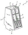
Fig. 1 be according to the first embodiment of the present invention for assembling the transparent view of external member of nozzle module,
Fig. 2 is the transparent view that utilizes the nozzle module of the external member assembling shown in Fig. 1,
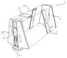
Fig. 3 is according to a second embodiment of the present invention for assembling the transparent view of external member of nozzle module,
Fig. 4 is the transparent view that utilizes the nozzle module of the external member assembling shown in Fig. 3,
Fig. 5 is a third embodiment in accordance with the invention for assembling the transparent view of external member of nozzle module,
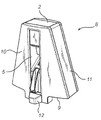
Fig. 6 is the transparent view that utilizes the nozzle module of the external member assembling shown in Fig. 5,
Fig. 7 is the transparent view of nozzle module in the time being assembled in fuel allocation units that utilizes the assembling of external member shown in Fig. 1.
The specific embodiment
Fig. 1 illustrates according to the first embodiment of the present invention for assembling the external member 1 of nozzle module.This external member 1 comprises top board 2, two chevron cover plates 3, respectively comprises two side structures 4 of nozzle casing 5 and the reinforcing element 6 for stabilized nozzle module.Top board 2 has opening 7, and it is suitable for being formed for the lead-through of the duct arrangement that extends through nozzle module.
In Fig. 2, nozzle module 8 is shown, this nozzle module 8 utilizes according to the external member 1 of the first embodiment of the present invention and assembles.Two opposition chevron cover plates 3 are parallel and respectively extend to top board 2 in taper mode from the bottom section 9 of nozzle module 8.Two opposite side structures 4 that respectively comprise nozzle casing 5 extend to top board 2 in the mode of mutually converging from the bottom section 9 of nozzle module 8.Two opposition chevron cover plates 3 and two opposite side structures 4 are all attached to top board 2.The nozzle casing 5 of each side structure 4 therewith entirety forms.Nozzle module 8 also can comprise reinforcing element 6 (not shown) of the inside that is configured in described nozzle module 8.One of lateral areas section who is to be understood that nozzle module can seal, that is, this lateral areas section can be formed by side cover plate.
Fig. 3 illustrates according to a second embodiment of the present invention for assembling the external member 1 of nozzle module 8.External member 1 comprises top board 2, two chevron cover plates 3, respectively comprises four side structures 4 of nozzle casing 5 and the reinforcing element 6 for stabilized nozzle module 8.Top board 2 has opening 7, and it is suitable for being formed for the lead-through of the duct arrangement that extends through nozzle module 8.
Fig. 5 illustrates that a third embodiment in accordance with the invention is for assembling the external member 1 of nozzle module 8.External member 1 comprises top board 2, chevron cover plate 3, comprise the chevron structure 10 of nozzle casing 5, two opposite side cover plates 11 and the reinforcing element 6 for stabilized nozzle module.
The external member of inventing can comprise that member (with following number and modification, chevron cover plate 3, chevron structure 10, side cover plate 11, side structure 4, top board 2 and reinforcing element 6),, make to assemble any the nozzle module according to three kinds of configurations mentioned above.Therefore, top board 2 can comprise combination, and top board is closed and be suitable for assembling according to the nozzle module 8 of the embodiment shown in Fig. 6 therein.Top board 2 also can comprise combination, and top board has opening 7 and is suitable for assembling according to the nozzle module 8 of the embodiment shown in Fig. 2 or Fig. 4 therein, and opening 7 is suitable for being formed for the lead-through of duct arrangement.And reinforcing element 6 can comprise combination, reinforcing element comprises the supporting construction that is suitable for supporting the duct arrangement that extends through nozzle module 8 therein.
Fig. 7 illustrates the fuel allocation units 22 with two nozzle modules 8, and each nozzle module 8 utilizes according to the external member 1 of the first embodiment of the present invention and assembles.Fuel allocation units 22 comprise six dissimilar modules 13,14,8,15,16,17.Module 13,14,8,15,16,17 is made up of base module 13, electronic module 14, two nozzle modules 8, two column modules 15, top module 16 and display modules 17.
Electronic module 14 is configured in the top of base module 13, and nozzle module 8 is configured in the top of base module 13, and column module 15 is configured in the top of nozzle module 8 and top module 16 and is configured in the top of column module 17.
Block configuration is above another module or be configured in the connection between module that the top of another module causes extending in the horizontal direction.
The hydraulic part (not shown) that base module 13 comprises fuel allocation units 22, such as fuel metering device, valve, pump, vapor-recovery system etc.The outside of base module 13 comprises the display surface for printing.Electronic module 14 comprises the device for controlling fuel allocation units 22 and is included in the user interface 18 on its one of outside face.User interface 18 is suitable for that Pump data is shown and is equipped to the payment of processing the fuel after fuel up.Each of nozzle module 8 is fixed two nozzle casings 5, in each side of nozzle module 8, has one, and this nozzle casing 5 is intended to carry separately nozzle 19.Column module 15 is configured in the top of nozzle module 8 or is configured in the top of nozzle module 8, to raise and support, top module 16 in the time of assembling.The display surface that top module 16 self comprises for printing.But top module 16 is also suitable for receiving display module 17, it also comprises the display surface for printing.
In the time of assembling fuel allocation units 22, base module 13 is located on the ground in the appropriate location for fuel allocation units 22.Electronic module 14 is configured in the top of base module 13, and user interface 18 will be positioned at the suitable height of the user to fuel allocation units 22 thus.Pass through openings is provided as by described user interface 18 from base module 13 separately in electronic module 14.Two nozzle modules 8 are configured in the top of base module 13, in each side of electronic module 14, have one.Each nozzle module 8 carries two nozzle casings 5, and it is arranged to toward each other and is suitable for fanging noz(zle) 19 separately.Column module 15 is configured in each top of nozzle module 8.Two column modules 15 are carried again top module 16, and it is configured in the top of two column modules 15.Display module 17 is configured on top module 16, and display module 17 parts are around top module 16.Display module 17 comprises the display surface for printing.
Fuel allocation units 22 have the duct arrangement 20 and the pipe 21 that are connected thereto, for from fossil fuel container (not shown) transfer the fuel to nozzle 19.Duct arrangement 20 extends to nozzle module 8 and passes through nozzle module 8 from fossil fuel container.Above nozzle module 8, duct arrangement 20 is connected to the pipe 21 of this special side that belongs to fuel allocation units 22.The identical nozzle module 8 that is connected to the opposite side that is arranged in fuel allocation units 22 between duct arrangement 20 and pipe 21 forms.Then pipe 21 extends to nozzle 19 separately from nozzle module 8 via column module 15 and top module 16 again.By this way, duct arrangement 20 is surrounded by base module 13, nozzle module 8, and pipe 21 is surrounded by column module 15 and top module 16 parts.But duct arrangement 20 can extend to column module 15 and be connected to the pipe 21 column module 15 from described base module 13.Then pipe 21 extends to nozzle 19 from column module 15 via top module 16.Another possibility is that duct arrangement 20 extends to top module 16 from base module 13.Utilize this scheme, then pipe 21 directly extends to nozzle 19 from top module 16.
Each reinforcing element 6 can comprise the supporting construction that is suitable for supporting the duct arrangement 20 that extends through nozzle module 8.
According to a second aspect of the invention, fuel allocation units are provided as and comprise the nozzle module utilizing according to the external member assembling of above-mentioned feature.
The present invention is main above to be described with reference to some embodiment.But, one of ordinary skill in the art will readily recognize that, in as the scope of the present invention of claims definition, other embodiment except above disclosed embodiment equally may.
Claims (11)
1. an external member (1), comprises
Top board (2),
Chevron cover plate (3),
Respectively comprise the chevron structure (10) of nozzle casing (5),
Side cover plate (11), and
Respectively comprise the side structure (4) of nozzle casing (5),
This external member (1) is suitable for assembling nozzle module (8), and it has two opposition chevron sections, two opposite side sections and top section according to any in following three kinds of configurations:
A) described top section forms by one in described top board (2); Each in described two opposition chevron sections forms by one in described chevron cover plate (3); At least one in described two opposite side sections be by respectively comprising that one in the described side structure (4) of nozzle casing (5) forms,
B) described top section forms by one in described top board (2); Each in described two opposition chevron sections forms by one in described chevron cover plate (3); And at least one in described two opposite side sections comprises at least one in the described side structure (4) that respectively comprises nozzle casing (5),
C) described top section forms by one in described top board (2); One in described two opposition chevron sections forms by one in described chevron cover plate (3); Another in described two opposition chevron sections is by respectively comprising that one in the described chevron structure (10) of nozzle casing (5) forms; And each in described two opposite side sections forms by one in described side cover plate (11).
2. external member according to claim 1 (1), it is characterized in that, described two opposition chevron sections of described nozzle module (8) are parallel and respectively extend to described top section in taper mode from the bottom section (9) of described nozzle module (8).
3. external member according to claim 1 and 2 (1), is characterized in that, described two opposite side sections extend to described top section in the mode of mutually converging from the bottom section (9) of described nozzle module (8).
4. external member according to claim 1 and 2 (1), is characterized in that, the described nozzle casing (5) of each chevron structure (10) therewith entirety forms.
5. external member according to claim 1 and 2 (1), is characterized in that, the described nozzle casing (5) of each side structure (4) therewith entirety forms.
6. external member according to claim 1 and 2 (1), is characterized in that, each in described chevron structure (10) also comprises pipe outlet (12).
7. external member according to claim 6 (1), is characterized in that, the described pipe outlet of each chevron structure (10) therewith entirety forms.
8. external member according to claim 1 and 2 (1), it is characterized in that, also comprise the reinforcing element (6) for stabilized nozzle module (8), each in described reinforcing element (6) is assembled in the nozzle module (8) with each of described three kinds of configurations.
9. external member according to claim 8 (1), it is characterized in that, described reinforcing element (6) comprises the combination of reinforcing element, wherein, each reinforcing element comprises the supporting construction that is suitable for supporting the duct arrangement (20) that extends through described nozzle module (8).
10. external member according to claim 1 and 2 (1), it is characterized in that, described top board (2) comprises the combination of top board, wherein, each top board has at least one opening (7), and it is suitable for being formed for extending through the lead-through of the duct arrangement (20) of described nozzle module (8).
11. 1 kinds are used to the fuel allocation units (12) of means of delivery fuel up, comprise the nozzle module (8) utilizing according to external member (1) assembling described in any one in claim 1 to 10.
Applications Claiming Priority (1)
| Application Number | Priority Date | Filing Date | Title |
|---|---|---|---|
| PCT/EP2009/063624 WO2011044956A1 (en) | 2009-10-16 | 2009-10-16 | Kit of parts for a module having a nozzle boot and a fuel dispensing unit having a nozzle module assembled with such a kit of parts |
Publications (2)
| Publication Number | Publication Date |
|---|---|
| CN102712455A CN102712455A (en) | 2012-10-03 |
| CN102712455B true CN102712455B (en) | 2014-06-11 |
Family
ID=42335078
Family Applications (1)
| Application Number | Title | Priority Date | Filing Date |
|---|---|---|---|
| CN200980162968.1A Expired - Fee Related CN102712455B (en) | 2009-10-16 | 2009-10-16 | Kit of parts for a module having a nozzle boot and a fuel dispensing unit having a nozzle module assembled with such a kit of parts |
Country Status (9)
| Country | Link |
|---|---|
| US (3) | US8662348B2 (en) |
| EP (1) | EP2488442B1 (en) |
| CN (1) | CN102712455B (en) |
| BR (1) | BR112012008906A2 (en) |
| EG (1) | EG26824A (en) |
| ES (1) | ES2445696T3 (en) |
| IN (1) | IN2012DN03286A (en) |
| PT (1) | PT2488442E (en) |
| WO (1) | WO2011044956A1 (en) |
Families Citing this family (3)
| Publication number | Priority date | Publication date | Assignee | Title |
|---|---|---|---|---|
| IN2012DN03286A (en) * | 2009-10-16 | 2015-10-23 | Dresser Wayne Ab | |
| IN2012DN03287A (en) | 2009-10-16 | 2015-10-23 | Dresser Wayne Ab | |
| USD988371S1 (en) * | 2021-10-27 | 2023-06-06 | ECOTANK s. r. o. | Windshield washer fluid dispensing machine for service station |
Citations (6)
| Publication number | Priority date | Publication date | Assignee | Title |
|---|---|---|---|---|
| US3027211A (en) * | 1959-05-27 | 1962-03-27 | Tokheim Corp | Dispenser frame and housing construction |
| US3342537A (en) * | 1965-04-07 | 1967-09-19 | John Wood Company | Liquid dispensing apparatus |
| CN2055820U (en) * | 1989-09-02 | 1990-04-11 | 魏延基 | Electric fuelling device with doublegun electronic counter |
| US6167922B1 (en) * | 1999-05-05 | 2001-01-02 | Tokheim Corporation | Water deflection system for use in fuel dispenser cabinets |
| US6328060B1 (en) * | 2000-01-26 | 2001-12-11 | Dresser, Inc. | Gasoline dispensing unit and method with improved hose handling |
| CN101045523A (en) * | 2006-03-28 | 2007-10-03 | 株式会社龙野 | Oil supplying apparatus |
Family Cites Families (15)
| Publication number | Priority date | Publication date | Assignee | Title |
|---|---|---|---|---|
| US1955712A (en) * | 1930-05-14 | 1934-04-17 | John Wood Mfg Co | Liquid dispensing apparatus |
| US2150025A (en) * | 1936-09-21 | 1939-03-07 | Sf Bowser & Co Inc | Dispensing apparatus |
| US3178057A (en) * | 1964-03-11 | 1965-04-13 | John Wood Company | Pump operating mechanism |
| US3375050A (en) * | 1964-11-30 | 1968-03-26 | Bolling H. Sasnett Jr. | Gasoline pump casing |
| US4195674A (en) * | 1978-02-15 | 1980-04-01 | Pacific Oil Marketing Equipment Company | Protective hood for a vapor recovery nozzle |
| DE2807976B2 (en) * | 1978-02-24 | 1980-01-10 | Dresser Europe S.A. Niederlassung Einbeck, 3352 Einbeck | Protection device for a fuel dispenser |
| US4186850A (en) * | 1978-05-01 | 1980-02-05 | Mahar & Parsons | Gasoline pump assembly and lock arrangement especially suitable for use therewith |
| US4611729A (en) * | 1984-08-28 | 1986-09-16 | Dresser Industries, Inc. | Universal nozzle boot for fuel dispenser |
| US5083846A (en) * | 1990-04-10 | 1992-01-28 | Gilbarco, Inc. | Door panel for multiple product fuel dispensers |
| EP0675074A1 (en) * | 1994-03-08 | 1995-10-04 | Equipement Industriel Normand France | Fuel dispensing apparatus able to be transformed from an apparatus dispensing a single product to an apparatus dispensing multiple products |
| US20050144859A1 (en) * | 2001-10-25 | 2005-07-07 | Keter Plastic Ltd. | Construction kit |
| US6843025B2 (en) * | 2001-10-25 | 2005-01-18 | Keter Plastic Ltd. | Construction kit |
| ES2402052T3 (en) * | 2006-05-24 | 2013-04-26 | Dresser Wayne Ab | Nozzle housing protruding for fuel dispenser |
| US20100258587A1 (en) * | 2009-04-13 | 2010-10-14 | Wheeler Loyde A | Windshield Washer Fluid Dispenser |
| IN2012DN03286A (en) * | 2009-10-16 | 2015-10-23 | Dresser Wayne Ab |
-
2009
- 2009-10-16 IN IN3286DEN2012 patent/IN2012DN03286A/en unknown
- 2009-10-16 EP EP09740879.3A patent/EP2488442B1/en active Active
- 2009-10-16 WO PCT/EP2009/063624 patent/WO2011044956A1/en active Application Filing
- 2009-10-16 CN CN200980162968.1A patent/CN102712455B/en not_active Expired - Fee Related
- 2009-10-16 US US13/502,288 patent/US8662348B2/en active Active
- 2009-10-16 BR BR112012008906A patent/BR112012008906A2/en not_active IP Right Cessation
- 2009-10-16 PT PT97408793T patent/PT2488442E/en unknown
- 2009-10-16 ES ES09740879.3T patent/ES2445696T3/en active Active
-
2012
- 2012-04-17 EG EG2012040709A patent/EG26824A/en active
-
2014
- 2014-01-21 US US14/159,999 patent/US9126819B2/en active Active
-
2015
- 2015-08-21 US US14/832,519 patent/US9802812B2/en active Active
Patent Citations (6)
| Publication number | Priority date | Publication date | Assignee | Title |
|---|---|---|---|---|
| US3027211A (en) * | 1959-05-27 | 1962-03-27 | Tokheim Corp | Dispenser frame and housing construction |
| US3342537A (en) * | 1965-04-07 | 1967-09-19 | John Wood Company | Liquid dispensing apparatus |
| CN2055820U (en) * | 1989-09-02 | 1990-04-11 | 魏延基 | Electric fuelling device with doublegun electronic counter |
| US6167922B1 (en) * | 1999-05-05 | 2001-01-02 | Tokheim Corporation | Water deflection system for use in fuel dispenser cabinets |
| US6328060B1 (en) * | 2000-01-26 | 2001-12-11 | Dresser, Inc. | Gasoline dispensing unit and method with improved hose handling |
| CN101045523A (en) * | 2006-03-28 | 2007-10-03 | 株式会社龙野 | Oil supplying apparatus |
Also Published As
| Publication number | Publication date |
|---|---|
| IN2012DN03286A (en) | 2015-10-23 |
| US8662348B2 (en) | 2014-03-04 |
| EP2488442A1 (en) | 2012-08-22 |
| EP2488442B1 (en) | 2013-12-11 |
| US20120199242A1 (en) | 2012-08-09 |
| BR112012008906A2 (en) | 2019-09-24 |
| US20140174601A1 (en) | 2014-06-26 |
| US9802812B2 (en) | 2017-10-31 |
| US20150353341A1 (en) | 2015-12-10 |
| ES2445696T3 (en) | 2014-03-04 |
| WO2011044956A1 (en) | 2011-04-21 |
| EG26824A (en) | 2014-10-08 |
| US9126819B2 (en) | 2015-09-08 |
| CN102712455A (en) | 2012-10-03 |
| PT2488442E (en) | 2014-02-20 |
Similar Documents
| Publication | Publication Date | Title |
|---|---|---|
| CN102712455B (en) | Kit of parts for a module having a nozzle boot and a fuel dispensing unit having a nozzle module assembled with such a kit of parts | |
| JP5789048B2 (en) | Mobile fuel supply station | |
| CN102712457B (en) | Fuel dispensing unit for refuelling vehicles and a method for assembling such a fuel dispensing unit | |
| WO1999025644A1 (en) | Fuel dispensing system | |
| CN104584964A (en) | Artificial rainfall system | |
| CN102712458A (en) | Module with nozzle boot for a fuel dispensing unit | |
| CN101439327A (en) | Backpack high-pressure electric sprayer | |
| CN203737508U (en) | Dispensed-adhesive weighing and vacuum cleaning structure of high-speed injection valve | |
| US20120186666A1 (en) | Below ground fuel dispenser system and method | |
| CN204900143U (en) | Get ready and hit vertical high -efficient hydroelectric set to one side | |
| CN207089030U (en) | A kind of multi-functional charging pile | |
| CN102791614A (en) | Fuel dispensing unit with hinged door | |
| CN206909319U (en) | Automatic atomising spray system | |
| CN207848096U (en) | A kind of electronic control hydraulic station | |
| CN205840461U (en) | A kind of communication tower integration charging pile | |
| CN203184143U (en) | Multifunctional automatic-control vehicle-mounted remote fog-jetting device | |
| CN207060003U (en) | Equipment work station assembly for vehicle cleaning equipment | |
| CN202362864U (en) | Oil product delivery fuelling vehicle | |
| CN202754302U (en) | Medicine dispensing machine | |
| CN210577243U (en) | Module-assembled waterproof power metering box | |
| AU711595B2 (en) | Fuel dispensing system | |
| CN206262713U (en) | A kind of transparent top spray | |
| Payne | Wall Street”“Financing…”“Banking…” What Happened to Technology? | |
| CN203235615U (en) | Bionic numerical control air bursting fountain | |
| CN102161465A (en) | Refueling device |
Legal Events
| Date | Code | Title | Description |
|---|---|---|---|
| C06 | Publication | ||
| PB01 | Publication | ||
| C10 | Entry into substantive examination | ||
| SE01 | Entry into force of request for substantive examination | ||
| C14 | Grant of patent or utility model | ||
| GR01 | Patent grant | ||
| CF01 | Termination of patent right due to non-payment of annual fee | ||
| CF01 | Termination of patent right due to non-payment of annual fee |
Granted publication date: 20140611 Termination date: 20161016 |