CN102705856A - Coal flow splitters and distributor devices - Google Patents
Coal flow splitters and distributor devices Download PDFInfo
- Publication number
- CN102705856A CN102705856A CN2012100374246A CN201210037424A CN102705856A CN 102705856 A CN102705856 A CN 102705856A CN 2012100374246 A CN2012100374246 A CN 2012100374246A CN 201210037424 A CN201210037424 A CN 201210037424A CN 102705856 A CN102705856 A CN 102705856A
- Authority
- CN
- China
- Prior art keywords
- distributor
- current divider
- inlet
- outlet
- coal
- Prior art date
- Legal status (The legal status is an assumption and is not a legal conclusion. Google has not performed a legal analysis and makes no representation as to the accuracy of the status listed.)
- Granted
Links
Images


Classifications
-
- F—MECHANICAL ENGINEERING; LIGHTING; HEATING; WEAPONS; BLASTING
- F23—COMBUSTION APPARATUS; COMBUSTION PROCESSES
- F23K—FEEDING FUEL TO COMBUSTION APPARATUS
- F23K3/00—Feeding or distributing of lump or pulverulent fuel to combustion apparatus
-
- F—MECHANICAL ENGINEERING; LIGHTING; HEATING; WEAPONS; BLASTING
- F23—COMBUSTION APPARATUS; COMBUSTION PROCESSES
- F23K—FEEDING FUEL TO COMBUSTION APPARATUS
- F23K3/00—Feeding or distributing of lump or pulverulent fuel to combustion apparatus
- F23K3/02—Pneumatic feeding arrangements, i.e. by air blast
-
- F—MECHANICAL ENGINEERING; LIGHTING; HEATING; WEAPONS; BLASTING
- F23—COMBUSTION APPARATUS; COMBUSTION PROCESSES
- F23K—FEEDING FUEL TO COMBUSTION APPARATUS
- F23K2203/00—Feeding arrangements
- F23K2203/10—Supply line fittings
- F23K2203/105—Flow splitting devices to feed a plurality of burners
Abstract
A flow splitter for distributing solid particles flowing in a fluid through a piping system includes a divider housing. The divider housing has an inlet configured to connect to an upstream pipe and has a plurality of outlets, each outlet being configured to connect to a respective downstream pipe. A divider body is mounted within the divider housing. A plurality of divider vanes are included, each extending from the divider body to the divider housing. The divider housing, divider body, and divider vanes are configured and adapted to reduce non-uniformity in particle concentration from the inlet and to supply a substantially equal particle flow to each outlet.
Description
Technical field
The present invention relates to the distribution of solid particles flowing in fluid, and the coal particle that more specifically relates in the air stream that passes the coal pipeline system distributes.
Background technology
The device and method that the various coals that are used for powdered are transported to the coal combustion machine is known in this technology.Many in these a little devices to improving distribution of particles being used for transporting the coal pipeline system that coal goes to burn.
The coal power plant need be supplied coal and act as a fuel to produce thermoelectric effective ways.Raw coal usually in coal pulverizer or grinding machine by powdered to produce little coal particle or coal dust.The coal of powdered then must be transported to combustion chamber or combustor, and it can be used for burning herein.This utilizes the coal pipeline system to accomplish usually, and the coal particle that said coal pipeline system uses air to flow powdered is transported to nozzle from said grinding machine or pulverizer, and coal particle is injected in coal combustion machine or the combustion chamber at said nozzle place.Along with coal particle is advanced in passing the air stream of pipe-line system, in general the knee in pipeline and the geometric pipeline shape usually causes that uneven coal particle distributes.The dense accumulation zone that extends through the coal particle of pipe-line system is called coal " rope ".
The coal wiring causes various technical matters for the operation and the maintenance of coal measures system.The relatively poor distribution of coal particle may extend in the combustion zone, herein the local uneven discharging that usually causes NOX, CO and other pollutant of inefficient combustion and raising in the fuel/air mixture.It also can cause improve the standard in the coal ash unburned carbon contained, and this will reduce efficiency of combustion.And the high abrasion of the coal wiring of the assembly of bump and friction coal pipeline and combustion system causes pipeline and a large amount of erosions of other assembly in the said system, needing to cause running check, maintenance and replacement part.If do not check, keep in repair and replace, then exist abrasion from the coal wiring will cause the possibility of raising of costliness or the risk of disturbance of key component with mode timely.
A debatable especially dispensing head that assembly is the junction for the coal wiring, said connection are between single upstream line and two or more downstream branch pipelines, and (for example) is as be shown in the upper reaches of directed flame combustion machine-made egg-shaped or honey-comb coal briquets nozzle usually.In this dispensing head; If have the said dispensing head that flows into of coal rope; Then one in the tributary, downstream will usually receive the coal rope section of said stream, this means that one in the downstream nozzle will receive significantly more coal than other nozzle or the nozzle that is connected to the same allocated head.
Usually thought that these a little conventional methods and system are gratifying for its set purpose.Yet, for example, still have the needs of the system and method for the dispensing head downstream distribution of particles that permission is improved in this technology.Also still there are needs in this technology to this type of system and method that is easy to make and uses.The present invention provides the solution of these problems.
Summary of the invention
The present invention is directed to the new and useful current divider that is used for being distributed in the fluid solid particles flowing of passing pipe-line system.For example, said current divider can be and is used for being distributed in the coal current divider that the air that passes the coal pipeline system flows mobile coal dust.Current divider comprises dispenser housing, and it has through being configured to and is connected to the inlet of upstream line and has a plurality of outlets, and each exports through being configured to be connected to corresponding downstream line.Distributor body is installed in the said dispenser housing.Comprise a plurality of distributor blades, its each extend to said dispenser housing since said distributor body.Said dispenser housing, distributor body and the configuration of distributor vanes and be fed to each outlet through adjusting to reduce from the inhomogeneities in the granule density of said inlet and the grain flow that will equate substantially.
According to some embodiment, said distributor body is conical and coaxial being installed in the dispenser housing.Distributor body can diverge in the direction from the inlet of dispenser housing to its outlet, and can be substantially extends to its outlet from the inlet of dispenser housing.The expection inlet can be profile of tooth through the outer tusk at interval of placing that extends internally.Inlet and outlet can respectively be done for oneself circular or any other suitable shape.
In certain embodiments, a plurality of distributor blades comprise around the longitudinal axis isolated four the distributor blades on circumference that extend to outlet from the inlet of distributor body.The circle spacing of distributor blade can 90 ° be spaced apart uniformly.The distributor blade can be substantially extends to said outlet and can be separately and said longitudinal axis parallel alignment from said inlet.
The expection dispenser housing can comprise the vertical exit plate of the longitudinal axis that extends to outlet with the inlet of dispenser housing relatively and substantially with the inlet from distributor body.The outlet of dispenser head can be four round exits that define via said exit plate.Each distributor blade can four round exits mutually between the reply equably at interval.Exit plate can have rectangular periphery, and wherein one in the distributor blade is installed in the midpoint of its each side.Also expection each corner of side of connecting the rectangular periphery of exit plate can be circle, and can be substantially with outlet in corresponding one coaxial.
According to some aspect, inlet defines inlet area, and outlet defines open area, and the ratio of said inlet area and said discharge area can be about 1.0.Dispenser housing, distributor body and distributor blade can be through configurations and through adjusting to have less than about 3.2inH from the outlet that enters the mouth
2The pressure of O falls.
From below in conjunction with graphic detailed description of the preferred embodiment, the those skilled in the art will more easily understand these and other characteristic of system and method for the present invention.
Description of drawings
Hereinafter will graphicly be described in detail with reference to some to the preferred embodiments of the present invention, so that the technical staff in the field under the present invention will more easily understand and how make and use device and method of the present invention and need not carry out too much experiment, wherein:
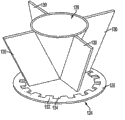
Fig. 1 is the perspective view of part of the example embodiment of coal pipeline system constructed according to the invention, and its displaying is used for the flow point from single upstream coal pipe is fitted on the diverter unit of four downstream coal pipes;
Fig. 2 is the decomposition diagram of part of the coal pipeline system of Fig. 1, and it shows from the upper reaches and the enlarged drawing of the current divider that downstream line is separated, and wherein exit plate is separated from current divider;
Fig. 3 is the decomposition diagram of the current divider of Fig. 2, and it shows the tusk of distributor body, distributor blade and profile of tooth inlet;
Fig. 4 is the sectional perspective view of part of the current divider of Fig. 2, the distributor body that its presentation group is fitted together, distributor blade and exit plate; And
Fig. 5 is the sectional perspective view of part of the current divider of Fig. 4, and it is illustrated in profile of tooth inlet, distributor body and distributor blade under the situation of the outer wall that removes dispenser housing and exit plate.
The specific embodiment
Referring now to graphic, wherein identical reference number identifies similar structures characteristic of the present invention or aspect.From explanation and explanation and unrestricted purpose, will be illustrated among Fig. 1 according to the partial view of the example embodiment of coal pipeline of the present invention system and usually with reference symbol 100 signs.As will describe, will be provided among Fig. 2 to 5 according to other embodiment or its aspect of coal pipeline of the present invention system.System and method of the present invention is used in the distribution of particles of improving pipeline division downstream in (for example) coal pipeline system and the analog.
With reference now to Fig. 2,, current divider 104 is installed between upstream line 102 and the downstream line 110 through being configured to.The round flange 112 of pipeline 102 can be tightened to the round flange 116 of current divider 104 by (for example) bolt (for example bolt 114) bolt.Four pipelines 110 are connected to current divider 104 through welding (or any other suitable interconnection technique).Expection (for example) is through being assemblied between the existing pipeline flanges, and current divider 104 can be installed between existing upstream coal pipe and four downstream line as the repacking to existing system, and said repacking needs few change or do not need change.Expect that also current divider (for example current divider 104) can be installed in the coal pipeline system of neotectonics.
With reference now to Fig. 3,, the intraware of current divider 104 is included in the dispenser housing 124, and as stated, it comprises the round entrance 126 that is installed to upstream coal pipe 102 through flange 116.Inlet 126 is profile of tooth through placing tusk 132 at interval outward; Said tusk 132 is placed outside between the breach 134 at interval and is extended radially inwardly (in Fig. 3; Start from clearly purpose, only mark some in tusk 132 and the breach 134) with reference symbol.Always have 16 tusks 132 and 16 breach 134, yet tusk/breach that the those skilled in the art will easily understand any suitable number can be used for different application and without departing from the spirit or scope of the invention.The port of export 127 of dispenser housing 124 is rectangle normally.Dispenser housing 124 comprises exit plate 108, its assembling the time be mounted to enter the mouth 126 relatively, vertical with longitudinal axis A.Exit plate 108 is rectangle normally, and the corner of the periphery of exit plate 108 and the port of export 127 have a circular corner.
The outside of dispenser housing 124 and inner surface define a shape usually, and it is for exporting the continuous mixture of the square cross section at 127 places to rectangle from the circular cross section of round entrance 126.Though the rectangle of dispenser housing 124 outlet 127 shows and be described as to be foursquare, rectangle or any other suitable substantially shape that the those skilled in the art will easily understand any other proper ratio all can be used for said outlet and without departing from the spirit or scope of the invention.
Still with reference to figure 3, exit plate 108 comprises five circular ports that define via it, and it comprises four outlet openings 140, and four downstream line 110 can be connected to current divider 104 herein.Remaining hole is a medium pore 142, and it is connected to the hollow port of export of distributor body 128 when assembling, so the center of current divider 104 is cones open, hollow.In the circular corner of exit plate 108 each is coaxial with the outlet opening 140 of corresponding vicinity.
Still be included in the dispenser housing 124 with reference to 3, four distributor blades 130 of figure, its therefrom intracardiac separately distributor body 128 radially extends to the lengthwise outer wall 106 of dispenser housing 124.Dispenser housing 124, distributor body 128 and distributor blade 130 is welded together, but also can use any other appropriate technology to connect and without departing from the spirit or scope of the invention.
Fig. 4 is illustrated in current divider 104 under the situation that removes outer wall 106 to show the layout of distributor body 128 and distributor blade 130.Four distributor blades 130 separate around longitudinal axis compartment with 90 ° on circumference of distributor body 128.On said direction of principal axis, four distributor blades 130 extend to the port of export from the arrival end of dispenser housing 124, and near the port of export of distributor body 128, stop.Such as among Fig. 5 displaying, the port of export of distributor body 128 is a hollow, as stated, its downstream is open and when assembling, is connected to medium pore 142.
Because the stream in current divider 104 balance line systems 100, so evenly distributing of coal particle in each downstream line 110 and air produces uniformly, than the combustor that flows to its downstream, nozzle or the analog of balance.The concrete shape of current divider 104 around the tilting zone of the circumference of device (is for example used; The surface of distributor body 128), sectional area (for example; Inlet 126 tooth-like part of anything) and the combination of volumetric (for example, the surface of blade 130) produce and intersect the zone of mixing.It is directed and be important for the optimum fuel balance that the accurate placement of current divider 104 is based on coal pipeline.The placement of showing and describing among this paper is exemplary, and the those skilled in the art will understand easily that any other suitable location can be used for given application and without departing from the spirit or scope of the invention.
Though preceding text are described under the exemplary background of four downstream line 110, the those skilled in the art will easily understand the downstream line that can use any suitable number and without departing from the spirit or scope of the invention.For example, the equilateral triangle configuration can replace square configuration to be used to have only the application of three downstream line.And; Though this paper describes under the exemplary background of coal pipeline system, the those skilled in the art will understand easily that method described herein and device can use with the stream that has in fluid the particle that flows of any other suitable type and without departing from the spirit or scope of the invention.
Method and system of the present invention (such as described above and graphic in institute's displayings) be provided for the system of distribution of particles, it has characteristic preferably, comprises that uniform dispenser head downstream flow.Though showed with reference to preferred embodiment and described Apparatus and method for of the present invention, the those skilled in the art will easily understand and can make a change and/or change and without departing from the spirit or scope of the invention it.
Claims (20)
1. current divider that is used for being distributed in the fluid solid particles flowing of passing pipe-line system, said current divider comprises:
A) dispenser housing, it has through being configured to and is connected to the inlet of upstream line and has a plurality of outlets, and each exports through being configured to be connected to corresponding downstream line;
B) distributor body, it is installed in the said dispenser housing; And
C) a plurality of distributor blades; Its each extend to said dispenser housing since said distributor body, wherein said dispenser housing, distributor body and the configuration of distributor vanes and be fed to each outlet through adjusting to reduce from the inhomogeneities in the granule density of said inlet and the grain flow that will equate substantially.
2. current divider according to claim 1, wherein said distributor body are conical and coaxial being installed in the said dispenser housing.
3. current divider according to claim 2, wherein said distributor body diverges in the direction from said its said outlet that enters the mouth of said dispenser housing.
4. current divider according to claim 3, wherein said distributor body extend to its said outlet from the said inlet of said dispenser housing substantially.
5. current divider according to claim 1, wherein said inlet is profile of tooth through the outer tusk at interval of placing that extends internally.
6. current divider according to claim 1, wherein said inlet and the outlet circle of respectively doing for oneself.
7. current divider according to claim 1, wherein said a plurality of distributor blades comprise the longitudinal axis around said distributor body on circumference with isolated four the distributor blades in 90 ° interval.
8. current divider according to claim 1, wherein said distributor blade extends to said outlet from said inlet substantially.
9. current divider according to claim 1, wherein said distributor blade separately with the longitudinal axis parallel alignment that extends to said outlet from said inlet.
10. current divider according to claim 1; Wherein said dispenser housing comprises the vertical exit plate of the longitudinal axis that extends to said outlet with the said inlet of said dispenser housing relatively and substantially with the said inlet from said distributor body; Four round exits of the said outlet of wherein said dispenser head for defining via said exit plate; Wherein said a plurality of distributor blade comprises around the said longitudinal axis isolated four distributor blades on circumference, wherein each distributor blade between said four round exits corresponding a pair of equably at interval.
11. current divider according to claim 10, wherein said exit plate has rectangular periphery, and one in the wherein said separator blade is installed in the midpoint of its each side.
12. current divider according to claim 11, each corner of side of said rectangular periphery that wherein connects said exit plate is through sphering.
13. current divider according to claim 12, each of wherein said exit plate through the sphering corner substantially with said outlet in corresponding one coaxial.
14. current divider according to claim 1, wherein said inlet defines inlet area, and said outlet defines open area, and the ratio of wherein said inlet area and said discharge area is about 1.0.
15. current divider according to claim 1, wherein said dispenser housing, distributor body and the configuration of distributor vanes and through adjusting to have less than about 3.2inH from the said said outlet that enters the mouth
2The pressure of O falls.
16. a coal current divider that is used for being distributed in the coal dust that the air stream that passes the coal pipeline system flows, said coal current divider comprises:
A) dispenser housing; It has through being configured to and is connected to the round entrance of upstream coal pipe and has the exit plate relative with said inlet; Said exit plate has passes four round exits that it defines, and each exports through being configured to be connected to corresponding downstream coal pipes;
B) be installed in distributor body in the said dispenser housing; And
C) a plurality of distributor blades; Its each extend to said dispenser housing since said distributor body, wherein said dispenser housing, distributor body and the configuration of distributor vanes and be fed to each outlet through adjusting to reduce to flow from the inhomogeneities in the coal particle concentration of said inlet and the coal particle that will equate substantially.
17. coal current divider according to claim 16; Wherein said distributor body is conical and coaxial being installed in the said dispenser housing; Wherein said distributor body extends to said exit plate from the said inlet of said dispenser housing substantially, and wherein said distributor body diverges in the direction from said its said outlet that enters the mouth of said dispenser housing.
18. coal current divider according to claim 16, wherein said inlet is profile of tooth through the outer tusk at interval of placing that extends internally.
19. coal current divider according to claim 16; Wherein said a plurality of distributor blade comprises around the longitudinal axis isolated four the distributor blades on circumference that extend to said outlet from said inlet; Wherein each distributor blade between said four outlets corresponding a pair of equably at interval; Wherein said distributor blade extends to said outlet from said inlet substantially; Wherein said distributor blade separately with said longitudinal axis parallel alignment; Wherein said exit plate has rectangular periphery, and one in the wherein said distributor blade is installed in the midpoint of its each side, and wherein connect said exit plate said rectangular periphery side each corner through sphering and substantially with said outlet in corresponding one coaxial.
20. coal current divider according to claim 16; Wherein said inlet defines inlet area; Said outlet defines open area; The ratio of wherein said inlet area and said discharge area is about 1.0, and wherein said distributor vanes configuration and through adjusting to have less than about 3.2inH from the said said outlet that enters the mouth
2The pressure of O falls.
Applications Claiming Priority (2)
| Application Number | Priority Date | Filing Date | Title |
|---|---|---|---|
| US13/048,921 | 2011-03-16 | ||
| US13/048,921 US8403602B2 (en) | 2011-03-16 | 2011-03-16 | Coal flow splitters and distributor devices |
Publications (2)
| Publication Number | Publication Date |
|---|---|
| CN102705856A true CN102705856A (en) | 2012-10-03 |
| CN102705856B CN102705856B (en) | 2016-11-30 |
Family
ID=
Cited By (4)
| Publication number | Priority date | Publication date | Assignee | Title |
|---|---|---|---|---|
| CN103335324A (en) * | 2013-07-05 | 2013-10-02 | 北京华清优燃科技有限公司 | Variable rotation speed rotation type coal dust distributor and distributing method thereof |
| CN108100678A (en) * | 2017-11-13 | 2018-06-01 | 福建鑫铭机械设备有限公司 | A kind of low-drag type stock distributor |
| CN108698088A (en) * | 2016-02-29 | 2018-10-23 | 通用电器技术有限公司 | System, method and the equipment of flow distribution for controlling solid particle |
| CN109681899A (en) * | 2018-12-26 | 2019-04-26 | 上海发电设备成套设计研究院有限责任公司 | Coal even separator and its application method is adjusted in a kind of station boiler |
Citations (5)
| Publication number | Priority date | Publication date | Assignee | Title |
|---|---|---|---|---|
| US1871853A (en) * | 1927-08-09 | 1932-08-16 | Joseph E Kennedy | Pneumatic transporting and distributing of pulverized material |
| US4392438A (en) * | 1981-06-22 | 1983-07-12 | R & D Associates | Coal transport system |
| WO2009134542A2 (en) * | 2008-04-30 | 2009-11-05 | Babcock Power Inc. | Anti-roping device for pulverized coal burners |
| WO2010021892A2 (en) * | 2008-08-21 | 2010-02-25 | Riley Power, Inc. | Deflector device for coal piping systems |
| CN102644934A (en) * | 2011-01-20 | 2012-08-22 | 巴布科克电力服务公司 | Coal flow balancing devices |
Patent Citations (5)
| Publication number | Priority date | Publication date | Assignee | Title |
|---|---|---|---|---|
| US1871853A (en) * | 1927-08-09 | 1932-08-16 | Joseph E Kennedy | Pneumatic transporting and distributing of pulverized material |
| US4392438A (en) * | 1981-06-22 | 1983-07-12 | R & D Associates | Coal transport system |
| WO2009134542A2 (en) * | 2008-04-30 | 2009-11-05 | Babcock Power Inc. | Anti-roping device for pulverized coal burners |
| WO2010021892A2 (en) * | 2008-08-21 | 2010-02-25 | Riley Power, Inc. | Deflector device for coal piping systems |
| CN102644934A (en) * | 2011-01-20 | 2012-08-22 | 巴布科克电力服务公司 | Coal flow balancing devices |
Cited By (6)
| Publication number | Priority date | Publication date | Assignee | Title |
|---|---|---|---|---|
| CN103335324A (en) * | 2013-07-05 | 2013-10-02 | 北京华清优燃科技有限公司 | Variable rotation speed rotation type coal dust distributor and distributing method thereof |
| CN103335324B (en) * | 2013-07-05 | 2015-10-28 | 北京新叶能源科技有限公司 | A kind of rotary pulverized coal distributor of variable speed and distribution method thereof |
| CN108698088A (en) * | 2016-02-29 | 2018-10-23 | 通用电器技术有限公司 | System, method and the equipment of flow distribution for controlling solid particle |
| CN108698088B (en) * | 2016-02-29 | 2022-04-26 | 通用电器技术有限公司 | System, method and apparatus for controlling flow distribution of solid particles |
| CN108100678A (en) * | 2017-11-13 | 2018-06-01 | 福建鑫铭机械设备有限公司 | A kind of low-drag type stock distributor |
| CN109681899A (en) * | 2018-12-26 | 2019-04-26 | 上海发电设备成套设计研究院有限责任公司 | Coal even separator and its application method is adjusted in a kind of station boiler |
Also Published As
| Publication number | Publication date |
|---|---|
| US20120237304A1 (en) | 2012-09-20 |
| US8403602B2 (en) | 2013-03-26 |
| EP2500647B1 (en) | 2015-06-03 |
| JP6016395B2 (en) | 2016-10-26 |
| EP2500647A2 (en) | 2012-09-19 |
| EP2500647A3 (en) | 2014-01-15 |
| JP2012192404A (en) | 2012-10-11 |
Similar Documents
| Publication | Publication Date | Title |
|---|---|---|
| US8403602B2 (en) | Coal flow splitters and distributor devices | |
| CN102644934B (en) | Coal stream bascule | |
| CA2733238C (en) | Deflector device for coal piping systems | |
| CN103501917A (en) | Cyclone with a plurality of inlet ducts | |
| US6899041B2 (en) | Multi-spin mixer for particulate coal supply conduit | |
| CN203744284U (en) | Alternate diversion type pulverized coal distributor | |
| US8082860B2 (en) | Anti-roping device for pulverized coal burners | |
| CN102705856B (en) | Coal diverter and distributor device | |
| CN102954494A (en) | Flow adjustment orifice systems for fuel nozzles for a gas turbine engine | |
| JP4250084B2 (en) | Furnace system | |
| CN213577557U (en) | Static even diffusion equipment of power station buggy pipeline | |
| CN103392096B (en) | Tower dispenser in coal-fired power plant | |
| CN213513963U (en) | Dynamic uniform diffusion device for pulverized coal pipeline of power station | |
| CN112146121A (en) | Uniform diffusion system for pulverized coal pipeline of power station |
Legal Events
| Date | Code | Title | Description |
|---|---|---|---|
| C06 | Publication | ||
| PB01 | Publication | ||
| C10 | Entry into substantive examination | ||
| SE01 | Entry into force of request for substantive examination | ||
| C14 | Grant of patent or utility model | ||
| GR01 | Patent grant | ||
| CF01 | Termination of patent right due to non-payment of annual fee | ||
| CF01 | Termination of patent right due to non-payment of annual fee |
Granted publication date: 20161130 Termination date: 20210216 |