In telecommunication, usually use optical cable, wherein the synthetic parallel optical fibre set that has public plastic coating of optical fibre set forms fibre ribbon.
Several then fibre ribbons stack together and are contained in and are called, and " in each vertical groove of the load-carrying unit of fluting separation scraper (slotted spacer) or fuse, these vertical grooves are spiral, and are that spirality can be out or close.
The line of making just like a metal or fibrous glass one class material in the position of optical cable axle is as strong element, and there are several coating with special protective effect the outside at the fluting fuse.
The optical cable of the above-mentioned type is commonly referred to " optical fiber ribbon cable ".
Manufacturing firm can provide the end to ward off out, and directly links the optical fiber ribbon cable of specified device or another optical cable when mounted, and the optical cable that can receive optical cable with connector device or other optical cables at the scene also can be provided; Another kind of way is the local directly prepackage upper binding head that optical cable is installed at the optical cable that is different from design by manufacturing firm or user.
The optical cable of pre-add-in connectors has many benefits, particularly the operation of add-in connectors can be carried out in suitable place under controlled condition, thereby guarantee best effect, also because it can make the operation of shop optical cable relatively economize line, if this is owing to directly connector is housed, the just connection that can be scheduled to immediately optical cable.
Though but if finding the end when the cable of shop damages, the optical cable of the fibre ribbon of warding off out can remove the end of damage, the optical fiber ribbon cable that has connector must former state use, and therefore the connector that damages when the cable of shop is unallowed.
People know that the shop cable relates to the whole length that optical cable is pulled through underpass or pipeline from an end.
This makes optical cable and band (tape) connector be subjected to various types of stress inevitably, so band is needed special protection.
For spreading cable, known have a kind of device that is called drawing head, and it is fastened on the tension part of optical cable and a handle apparatus is arranged, and for example is an eyebolt or similar thing, can catch optical cable and introduce it and lay in the place by it.
When optical cable had end connector, drawing head also is necessary for connector provided one to lay the place, so that can protect connector.
In addition, after the optical cable supporting part mechanically was fastened to a stiffener as a destination apparatus part, drawing head also must be able to hold the surplus part that makes the fibre ribbon that optical fiber can connect in the position of needs.
In known drawing head, for this purpose, the surplus of fibre ribbon partly is to keep or the strand form, opens when connecting again, and for laying connector, also provides non-yielding prop in described drawing head.
But these solutions are used in the optical cable (for example more than 400 optical fiber) of high reserves (high-potent-ial) usually, it is to be placed in the big cable pipe, to low reserves (low-potential) (for example containing 100 optical fiber) optical cable, cable pipe size reduces (less than 60+60mm), and is just inconvenient.
In fact, when the surplus part coiled strand shape of the fibre ribbon of forming optical fiber ribbon cable, they are bent, have been found that when little bending diameter, for example less than 30 millimeters, keep a period of time, analogy is put a period of time in the storehouse when the optical cable that drawing head separately is housed, and unacceptable reduction appears in the transmission capacity of optical fiber.
Therefore large diameter optical cable can be accepted corresponding large diameter drawing head, it can hold into the surplus part of the fibre ribbon of strand form, this strand bending radius does not cause the tangible transmission decay of optical fiber, the drawing head of above-mentioned diameter can not be used for being placed on cable pipe separately, the small diameter fibre optic cables in the closely-spaced place of vallecular cavity one class.
Therefore need a kind of optical fiber ribbon cable drawing head of minor diameter, do not make optical fiber be curved little radius, thereby make described drawing head can be used for all big or small optical fiber ribbon cables.
The object of the present invention is to provide a kind of drawing head of minor diameter and provide a firm lay down location, protect fibre ribbon and connector to avoid stress and possible water infiltration simultaneously the connector that is contained in advance on each fibre ribbon.
An object of the present invention is provides a drawing head to optical fiber ribbon cable; fibre ribbon is formed a plurality of band groups in the optical fiber ribbon cable; be placed in each spiral groove of the fluting fuse that surrounds an axial strong element; outer protection and/or tension coating surround described fuse; described fibre ribbon is equipped with end connector separately; it is characterized in that; it comprises a traction element; the described axial strong element and the tensile elements of one end and optical cable link; the other end and a handle element link; described traction element is surrounded by the fluting body of its length of a flexibility corresponding to predetermined fibre ribbon length surplus; described fluting body has groove can hold with the groove of grooved cable fuse to lay fibre ribbon with aiming at; a deformable supporting mass that also surrounds described traction element is followed described fluting body; this supporting mass has the recess of the aligning that vertically separates; its position is not determined in advance; be used for laying the end connector of the fibre ribbon of each the fibre ribbon group in the groove that is in the optical cable fuse; also comprise pipe linkage section and axial preload device; the former provides outer protection, and the latter compensates the elongation of traction element when having tension.
Particularly, drawing head comprises a connector, it is fastened on the optical cable strength members rigidly, be connected with a connecting rod with this strong element is coaxial, this connector have on the outer surface with the optical cable fuse on place the same number of groove of fibre ribbon, cross section and direction, described fibre ribbon are not introduced to the bending variation groove of connector basically from the groove of optical cable fuse.
The fluting body that surrounds traction element has the fastener of aiming at connector, can prevent that this fluting body from rotating with respect to described connector, to keep the aligned relationship of its groove and connector groove.
In drawing head of the present invention, flexible fastening device, to connector locking fluting body, when being subjected to tension, the elongation of energy compensation link.
Traction element is fastened to the mechanical adapting device of the one or more outer tension coating of optical cable, comprises a tubular body of axially being close to facing to connector, be fixed on the sleeve on the one or more tension coating that are fastened on optical cable rigidly.
Tubular body and be integral with the sleeve shaped that tight screw-threaded engagement is fixed on the optical cable tensile layer, the device that also has anti-relatively screw thread to unscrew, it is placed between tubular body and the connector better.
After removing connecting rod, connector presents and can carry out the device that machinery cooperates to optical cable and external equipment.
Outside the fluting body tubulose mechanical protection section or tube portion are arranged, these sections adopt each other and flexibly connect, and adopt the ball-and-socket of the adjacent surface that has the restraint angle to connect better.
Flexible fluting body has the spiral groove, the groove on its pitch ratio optical cable fuse big.
In above-mentioned preferred embodiment, the diameter of flexible fluting body is 2 to 5 times of optical cable fluting fuse diameter, and the pitch of groove is increased to 1.2 to 1.5 times.
Connector has a zone of transition that is used for fibre ribbon at least, the spiral surrounding diameter of fibre ribbon even variation between the screw diameter of groove screw diameter that equals optical cable fluting fuse and flexible body inlet groove wherein, the length of described zone of transition is not less than 1/7 of optical cable fuse groove pitch.
The length of zone of transition at 1/5 to 1/2 of optical cable fuse groove pitch better.
Connector increases towards the direction trench depth of its fastening optical cable, and described groove is the part of zone of transition.
Following description with reference to accompanying drawing makes details of the present invention become clearer.In the accompanying drawings:
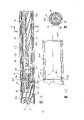
As depicted in figs. 1 and 2, the fluting fuse optical cable of dress fibre ribbon has one by metal, the axial strong element 1 that the heart line that glass fibre one class material is made constitutes, and it is surrounded by a fuse 2 of being done by plastics.Spirality groove 3 is arranged on the fuse 2, can lay for example 5 fibre ribbons of several stacked fibre ribbon 4(, every band is made up of 4 optical fiber).
Outside the fuse 2; there are one or more coating 4a wrapping fuse; be the layer of doing by aramid fibre (aramidic fibre) class material 5 then; it is a tension; in its outside is groove line shape sealing (damp proof) armor 6; for example made by plastics or metal material, the outside is a protection coating 7 again.
As shown in Figure 2, the optical cable of the above-mentioned type will be linked drawing head, and is stepped by its each layer in succession made subsequently, and it can be operated with drawing head, and this will carefully describe below.
Each adjacent part of drawing head of the present invention is shown in Fig. 3,4,7,8, it comprise a connector 8,8 have an end 9 can be fixed on heart line 1 the uncoated end portion 1a with predetermined length above, plastic deformation by end 9 is fastened on the 1a of end, makes connector 8 and heart line 1 form an integral body; As Fig. 4 and shown in Figure 6, it is vertically or the groove of spiral basically that connector 8 has several, its number, and the cross section will be connected with drawing head with pitch and the unanimity of the optical cable fuse 2 aimed at it; Diameter in the bottom surface of the free-ended described groove of connector 8 is bigger than the diameter of the corresponding groove of optical cable fuse 2; The fibre ribbon 4 of coming from the groove 3 of optical cable fuse 2 is contained in the described groove.
The groove of connector 8 is near end 9 time, and trench depth suitably increases, and fibre ribbon 8 path can be extended from optical cable fuse 2 to connector, and do not have local bending, and its state is not stepped.
In addition, connector 8 has a screw 11 coaxial with end 9, and the threaded portion 12a of the end 12 of connecting rod 13 is screwed into wherein, and connecting rod 13 comprises a metal cables 14 or similar tensile materials, and terminal 12 usefulness for example mechanical deformation are fastened on 14.
End 12 is easily fixed on the connector 8 by a pair of anti-tight (Countertightened) nut 15.
Outside the connecting rod 13 be one by deformable material as ducted body 16, for example these class plastics of teflon (PTEE) are better, having on the body 16 is vertical or spiral groove 17 basically, its number, consistent on cross section and pitch and the connector 8, and can be placed in fibre ribbon 4 in the described connector 8; Be to keep the aligning of groove on connector 8 and the body 16, the latter has the retainer (dog) 18 of an axial projections, in the respective cavities of the connector 8 that is designed to just in time to pack into, as shown in Figure 6.
From figure, can be clear that, groove 10 and 17 preferably has spirality to launch at connector 8 and ducted body 16 surfaces respectively, the groove 3 of their pitch and optical cable fuse 2 is consistent, perhaps under any circumstance, it does not produce tangible bending and increases being contained in fibre ribbon in the groove and 8 the transitional region from fuse 2 to connector.
The length of the ducted body 16 of belt grooves and that part of connecting rod 13 of its inside be contained in this ducted body groove in can be connected the length unanimity of that part of fibre ribbon of this generic operation as optical cable; For example the length of ducted body 16 can be between 50 centimetres to 1 meter, and when first the removing of traction, the fibre ribbon of respective length can be used for essential connection like this.
In ducted body 16 ends, near the other end of connecting rod 13, a sleeve 21 is arranged, its part 22 combines by for example plastic deformation and metal cables 14; Sleeve 21 has screw thread 23, and nut 24,25 is anti-thereon tight; These two nuts axially lock a dish type device 26, and an end of spring 27 is close on 26, and the other end of described spring acts on the ducted body 16.
The end of metal cables 14 have with 28, one handle elements that are used for drawing of metal cables 14 all-in-one-piece thread terminals be connected in it above, eyebolt 29 these class components for example.
In the outside of optical cable fuse 2 (Fig. 3) sleeve 30 is arranged, the fiber of optical cable layer 5 is drawn along its surface, described fiber is fixed on sleeve 30 and is fastened between the end 31 of an outer sleeve 32 of sleeve 30, and fibrage 5 and armor 6 can or use adhesives or similar techniques to combine selectively by plastic deformation.
The other end part 33 of outer sleeve 32 is fixed on the cable protection layer 7 in order, can choose sealant 7a wantonly and place in the middle of them, and there is screw thread at the middle part of sleeve 32, is used for assembling body 34, tightens up to 35 of body 34 and is close to connector 8.
Said structure makes cable armor layer 6, layer 5 and heart line 1 are integrally affected, and like this, the tensile load that acts on the optical cable can distribute by the design characteristics of optical cable itself, relatively move thereby avoided the tension masterpiece time spent to produce between each several part, this mobile meeting causes stress in fibre ribbon 4.
As shown in Figure 3, connector 8 has a hole radially, and a pin 36 inside can slide, and 36 inward-pointing end is cut into chamfering and is engaged with a grub screw 37 that is screwed in the threaded hole 11.
Tightening grub screw 37 makes pin 36 produce slip radially outward, make its end point 38 and body 34 engagements, stop it to rotate, guaranteed body 34 back-out of can not releasing by this way, thereby do not changed the distribution of tensile load between the different tensile elements of optical cable with respect to connector 8.
In addition, by preventing that supporting mass 8 and body 34 from relatively rotating, pin 36 can make terminal 12 be screwed in the threaded hole of connector 8 tighter, the braking action of pin 36 on body 34 directly locked the rotation of connector 8 and do not had the deformation element to add, thereby it can produce little rotation to optical fiber generation stress between connector 8 and optical cable.
Each the group fibre ribbon that comes out from each groove of optical cable fuse 2 is placed in the corresponding groove 10 of connector 8 then in the groove 17 of ducted body 16, keep basically simultaneously and same amount of bow in optical cable, end at ducted body 16, fibre ribbon is according to from lower band, the different length of Zeng Jiaing is split disconnected gradually, each band all connects connector separately, shown in Fig. 7 and 8.
Between element 21 and terminal 28, leave enough length L to place all connectors of each fibre ribbon group in succession, make between them not hinder mutually, be preferably in some space between them, when splitting disconnected fibre ribbon and loading onto connector, can allow certain tolerance like this.
Fibre ribbon and connector separately are placed in each corresponding groove 40 of tubulose supporting body 41 easily, and 41 usefulness deformable materials are made, and by the elastic deformation of material, connector is placed in there formation recess separately, has so just avoided collision, rocks or the like.
The end 35 that is close to body 34 is first in a series of tubular sections or the pipe portion 42, and these pipe portions flexibly connect each other, overlays on outside the ducted body 16, provides the protection of anti-mechanical stress to being contained in fibre ribbon on the described ducted body; Last section of described tubular sections is positioned near sleeve 21 places, and a tubulose armor 43 is right after in the back, but described armor surrounds deformation supporting mass 41, protection fibre ribbon and connector therein.
As shown in figure 10, each tubular sections 42 has and has the land portions 42a that radius is R on the end; And the other end has a corresponding conical surface 42b, design and the surperficial 42a of the tubular sections of adjacency contact; Surface 42a is subsequent with 42b to be respectively relative garden loop section 42c and 42d.
Armor 43 also shows same spherical end structure, and there is a conical contact face end 35 of body 34.
42 of adjacent tubular sections and tubular sections and body 34, the flexible connection that the tubulose armor is 43 obtains by this way, in the contact that keeps between them, also by apparent surface 42c, the contact of 42d has limited the angle between adjacent segment, thereby has limited the integrally bending radius that inner body 16 can bear.
With respect to the other end that contacts with tubular sections 42, an adjacent surface is arranged at tubulose armor 43, a ring 44 is arranged against it, being screwed in ring nut 46 extrusion springs 45 on terminal 28 screw threads is pushing away and is encircling 44, ring nut 46 clips ring 44, armor 43, tubular sections 42 and body 34.
Also be to be screwed in eyebolt 29 on terminal 28 to abut ring nut 46 and be screwed into, prevent loosening.
Under predetermined preload condition, spring 45 and 27 has guaranteed to abut mutually in the drawing head each several part and has still remained in contact with one another when connecting rod 13 is subjected to tractive force (for example when spreading optical cable) generation elastic elongation.
The water-stop of drawing head of the present invention guarantees that with an external seal armor 447 of being done by elastomeric material the sealing armor is assemblied on cable armor layer 7 and the element 34,42,43; Described armor can be used formation such as resilient material, material contracting with heat or banded coating.
Shown in the some chain line 47a among Fig. 8, sealing armor 47 extends to the part that it covers eyebolt 29 towards the free end of the drawing head of close eyebolt 29.
Except above-mentioned points, towards the drawing head end, water-stop is also with the garden annular seal 48 that is positioned at 43 of ring nut 46 and tubulose armors and be positioned at eye nut 29 and the seal 49 of 46 on ring nut guarantees.
According to another embodiment, replace armor, sealing or similar means can impose on each outer part of drawing head, and they are compressed mutually by spring 45; Between sleeve 32 and optical cable coating 7, can add sealant 7a and guarantee sealing, can also add sealant at the connection of thread of sleeve 32 and tubular body 34.
For drawing head of the present invention is used for optical cable, the end of optical cable wants light to shell the shape of ladder successively, has the heart line part that is enough to be fastenedly connected body 8 available, and the part of the fuse 2 consistent or more longer with the length of sleeve 30 is by strip off; The desired overall length of operation that fibre ribbon 4 keeps subsequently.
On ready like this optical cable, load onto sleeve 30 and outer sleeve 32 then, fibrage 5 is fixed between them, sleeve 32 is fixed on the groove line shape cable armor layer 6; Then connector 8 is fastened to heart line 1, and this most handy locating device of step or similar device are to guarantee correct aligning between optical cable groove 3 and the connector groove 8.
Fibre ribbon 4 is introduced groove 10 then and is fixed on the there with for example bandage 50 1 class things; Tubular body 34 is screwed on the sleeve 32, is close to connector 8 up to its other end, thereby by pin 36 and grub screw 37 lockings.
In advance connecting rod 13 is installed to the inside of fluting ducted body 16, they can do to slide relatively moving; Connecting rod is fixed in the connector 8, aims at the groove of ducted body 16 and connector 8; Then fibre ribbon 4 is positioned in the corresponding groove 17, can selects with the fixing (not shown) of bandage.
Then ducted body by coil 26 and spring 27 be fixed on the connecting rod 13.
Last fibre ribbon is rived and is measured by stepped, and connector is separately loaded onto in inner most beginning from each groove; Concerning connector, vertically fixing recess does not exist in groove 40, but their elastic deformations by material in described groove produce suitable recess in the mode of holding certainly, and when add-in connectors, a certain amount of error allows.
In fact, when detecting a fibre ribbon and connector bad connection, must split disconnected fibre ribbon at this connector place of next-door neighbour, and connect new connector; The minimum necessary length of connector that the length L of the supporting mass 41 that for this reason provides is laid given number than interference-free is big, is preferably the length that will grow a connector at least; When making a fault, just can repeat the operation of one or many reclosing connector to a fibre ribbon that is placed in every group of fibre ribbon in the groove; In the position of the optical fibres tape conjuncter on the same group not is mutually independently.
Be more preferably the length of big at least two connectors of length L, when making a fault, each group fibre ribbon reclosing connector can repeat twice at least like this.
Can avoid to repeat assembling the danger of whole operations that drawing head and fibre ribbon be connected with connector by this way, even when having the correct connector of installing in damaged connector or end also is so, damaged connector is in the end installed a collection of in the time especially dangerous.
In addition, lay the flexiblely advantage of clamp connector of connection device with the recess that the elastic properties of materials deformation of supporting mass 41 forms, the bump that can take place in the time of protecting them not spread optical cable like this such as rocks at influence.
After pawnshop cable step was finished, for carrying out fibre ribbon by the connection of connector separately, drawing head can be removed; Sealing armor 47 can peel off for this reason, repeats fitting operation with opposite order then, promptly removes tubulose armor 43, tubular sections 42, tubular body 41, ducted body 16 and connecting rod 13, like this optical fiber have enough length arrival separately connection or lay a little.
On the contrary, connector 8, tubular body 34 and sleeve 32 still keep being anchored on cable end, and they can form the mechanical tightening component between optical cable and device that optical cable will be connected.
As previously mentioned, the stress state of optical fiber or fibre ribbon and their bending (bending is reversed) are relevant; Drawing head of the present invention remains unchanged the stress state in drawing head substantially.
Fiber-like element to spiral surrounding, for example optical fiber or fibre ribbon, when pitch equated, the change of spiral surrounding diameter influenced the change of bending state, when particularly keeping pitch constant, the diameter that is added to cannulated body 16 from the increasing diameter of optical cable fuse 2 causes the increase of bending.
In a preferred embodiment, for keeping the fibre ribbon bending state constant as far as possible, according to structure of the present invention, the pitch of fluting ducted body 16 is different from fuse 2, when particularly ducted body cavity bottom diameter was 2 to 5 times of the cavity bottom diameters of fuse 2, the pitch of ducted body 16 was 1.2 to 1.5 times of pitch of fuse 2; Connector 8 is corresponding to a transitional region, and optical fiber carries out the transition to the screw diameter of fluting ducted body 16 gradually from the diameter of screw of optical cable fuse 2 therein.Simultaneously pitch also the groove pitch from optical cable change to the groove pitch of fluting ducted body 16.
The transitional region of general form can be basically from the end of sleeve 30 to the end of connector 8, it is equivalent to fibre ribbon and is not subjected to other constraint ground not to be around to a zone on the bigger diameter spirally; On the other hand, the also desirable shorter length of transitional region is if existence is to the further constraint in fibre ribbon orientation.
By top described with regard to the optical cable fuse diameter value and drawing head in regard to the diameter of fluting ducted body to transitional region defined above, 1/7 the length T (Fig. 3) that is not less than pitch in the optical cable can be provided easily, be preferably get described pitch 1/5 to 1/2 between.
As an example, when the cavity bottom diameter of the fluting fuse 2 of optical cable is 350 millimeters of 5 millimeters, pitch, the groove end diameter that fluting ducted body 16 is respectively laid fibre ribbon is 20 millimeters, under these conditions, the pitch that can prevent the suitable ducted body 16 that the transmissison characteristic of fibre ribbon 4 changes in time is 450 millimeters; Length T=100 that 8 transitional region is suitable from fuse 2 to connector millimeter.
According to another embodiment, the variation of the pitch that needs from the pitch of optical cable fuse 2 to fluting ducted body 16 at least can be partly at ducted body 16 itself by following realization: to the latter provide one from the pitch value that is equal to or slightly greater than fuse 2 to above-mentioned final peaked variable pitch, the increase with the diameter of ducted body own combines selectively.
Therefore structure of the present invention can make the stress state in the fibre ribbon keep low as much as possible; basically be not higher than the state that exists in the optical cable; can also originally when storing and spread cable, provide protection to fibre ribbon and the connector that is connected to connector; thereby avoided external load to be sent on the fibre ribbon; for example when the traction optical cable, also anti-sealing oozes to fibre ribbon.
Simultaneously, the diameter of this structure and optic cable diameter are comparable, so it can be introduced into design be used for laying optical cable minimizing the pipeline in gap in, and not causing fibre ribbon more greatly or too big bending, it is vertically to place basically in drawing head that fibre ribbon is guided to the necessary surplus length of each tie point; On the other hand, the length of drawing head is extended because 42 relative flexible connections of tubular sections can not destroy assembling dirigibility necessary when spreading the cable operation.
The scope that does not depart from general features of the present invention can also be made many changes.