CN102678729A - Rotating shaft gasket - Google Patents
Rotating shaft gasket Download PDFInfo
- Publication number
- CN102678729A CN102678729A CN2012101950144A CN201210195014A CN102678729A CN 102678729 A CN102678729 A CN 102678729A CN 2012101950144 A CN2012101950144 A CN 2012101950144A CN 201210195014 A CN201210195014 A CN 201210195014A CN 102678729 A CN102678729 A CN 102678729A
- Authority
- CN
- China
- Prior art keywords
- rotating shaft
- gasket
- shaft pad
- arc groove
- shim body
- Prior art date
- Legal status (The legal status is an assumption and is not a legal conclusion. Google has not performed a legal analysis and makes no representation as to the accuracy of the status listed.)
- Pending
Links
Images
Landscapes
- Chairs For Special Purposes, Such As Reclining Chairs (AREA)
Abstract
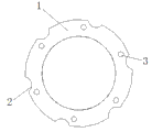
The invention discloses a rotating shaft gasket, which comprises an annular gasket body (1). The outer edge of the gasket body (1) is sunken to the center so that a plurality of arc-shaped grooves (2) are formed. The arc-shaped grooves (2) are formed on the outer ring of the rotating shaft gasket, so that a large quantity of raw materials can be saved under the condition that a rotating shaft and a rotating shaft seat are fixed stably. The rotating shaft gasket is easy to implement, attractive in appearance and low in cost, and has a good application prospect.
Description
Technical field
The present invention relates to a kind of rotating shaft pad, belonged to the mechanical fixation technical field.
Background technique
At present; Better fixing in order to increase between rotating shaft and the shaft seat in the mechanical device; The rotating shaft pad often is set between rotating shaft and shaft seat, so the rotating shaft pad obtained widely using, rotating shaft pad of the prior art is a toroidal; The use raw material are more, and higher cost is arranged in batch production process.
Summary of the invention
The objective of the invention is to overcome the problem that exists in the existing technology, a kind of rotating shaft pad is provided, the design of the outer toroid of rotating shaft pad is had arc groove; Under the situation that does not influence fixed effect between rotating shaft and the shaft seat; Can save great deal of raw materials, realize beautiful shape easily; With low cost, have a good application prospect.
In order to solve the problems of the technologies described above, the technological scheme that the present invention adopted is:
A kind of rotating shaft pad comprises the shim body of ring, and it is characterized in that: the outer edge part of said shim body forms several arc grooves to central concave.
Aforesaid a kind of rotating shaft pad is characterized in that: the quantity of said arc groove is 6, and is the outward edge that is distributed in shim body.
Aforesaid a kind of rotating shaft pad, it is characterized in that: the left side of said each arc groove is equipped with the fixed hole that is used for fixing.
The invention has the beneficial effects as follows: rotating shaft pad provided by the invention; Rotating shaft pad with outer toroid of arc groove under the situation that does not influence fixed effect between rotating shaft and the shaft seat, can be saved great deal of raw materials; Realize easily; Beautiful shape, with low cost, have a good application prospect.
Description of drawings
Fig. 1 is the structural representation of rotating shaft pad of the present invention.
Fig. 2 is the plan view of rotating shaft pad of the present invention.
The mark implication of accompanying drawing is following:
1: shim body; 2: arc groove; 3: fixed hole.
Embodiment
To combine Figure of description below, the present invention will be done further explanation.
Like Fig. 1 and shown in Figure 2, a kind of rotating shaft pad comprises the shim body 1 of ring, and the outer edge part of shim body 1 is to central concave; Form several arc grooves 2, the quantity of arc groove 2 is 6, and is the outward edge that is distributed in shim body 1; Such design does not influence fixed effect between rotating shaft and the shaft seat, but also can save great deal of raw materials, in the rotating shaft pad is produced in batches; Effect is more obvious; The left side of each arc groove 2 is equipped with the fixed hole 3 that is used for fixing, and it also is 6 that the quantity of fixed hole 3 and arc groove 2 are consistent, and can guarantee constant intensity between rotating shaft and the shaft seat.
In sum, rotating shaft pad provided by the invention, rotating shaft pad with outer toroid of arc groove; Under the situation that does not influence fixed effect between rotating shaft and the shaft seat, can save great deal of raw materials, realize easily; Beautiful shape, with low cost, have a good application prospect.
More than show and described basic principle of the present invention and major character and advantage of the present invention.The technician of the industry should understand; The present invention is not restricted to the described embodiments; That describes in the foregoing description and the specification just explains principle of the present invention; Under the prerequisite that does not break away from spirit and scope of the invention, the present invention also has various changes and modifications, and these variations and improvement all fall in the scope of the invention that requires protection.The present invention requires protection domain to be defined by appending claims and equivalent thereof.
Claims (3)
1. rotating shaft pad comprises the shim body (1) of ring, and it is characterized in that: the outer edge part of said shim body (1) forms several arc grooves (2) to central concave.
2. a kind of rotating shaft pad according to claim 1 is characterized in that: the quantity of said arc groove (2) is 6, and is the outward edge that is distributed in shim body (1).
3. a kind of rotating shaft pad according to claim 1 is characterized in that: the left side of said each arc groove (2) is equipped with the fixed hole (3) that is used for fixing.
Priority Applications (1)
| Application Number | Priority Date | Filing Date | Title |
|---|---|---|---|
| CN2012101950144A CN102678729A (en) | 2012-06-14 | 2012-06-14 | Rotating shaft gasket |
Applications Claiming Priority (1)
| Application Number | Priority Date | Filing Date | Title |
|---|---|---|---|
| CN2012101950144A CN102678729A (en) | 2012-06-14 | 2012-06-14 | Rotating shaft gasket |
Publications (1)
| Publication Number | Publication Date |
|---|---|
| CN102678729A true CN102678729A (en) | 2012-09-19 |
Family
ID=46811114
Family Applications (1)
| Application Number | Title | Priority Date | Filing Date |
|---|---|---|---|
| CN2012101950144A Pending CN102678729A (en) | 2012-06-14 | 2012-06-14 | Rotating shaft gasket |
Country Status (1)
| Country | Link |
|---|---|
| CN (1) | CN102678729A (en) |
Cited By (3)
| Publication number | Priority date | Publication date | Assignee | Title |
|---|---|---|---|---|
| CN103591116A (en) * | 2013-11-15 | 2014-02-19 | 侯如升 | Slotted-type metal ring piece |
| CN107183092A (en) * | 2017-06-22 | 2017-09-22 | 无锡市锡东金属磁材厂 | Converter spindle spacer |
| CN107197889A (en) * | 2017-06-22 | 2017-09-26 | 无锡市锡东金属磁材厂 | Hot-air rotary furnace spindle spacer |
Citations (6)
| Publication number | Priority date | Publication date | Assignee | Title |
|---|---|---|---|---|
| SU812999A1 (en) * | 1979-04-12 | 1981-03-15 | Волгодонский Завод Атомного Энергетическогомашиностроения "Атоммаш" | Locking washer |
| BE1001224A6 (en) * | 1987-11-19 | 1989-08-22 | Combori Comptoir De Boulons Et | Elastically-distorting plane washer - distorts elastically in different areas during axial compression and may be conical and locally weakened by annular grooves |
| AT412988B (en) * | 2000-05-19 | 2005-09-26 | Wohlfarth Klaus | ADJUSTING RING AND METHOD FOR ITS MANUFACTURE |
| CN201953791U (en) * | 2011-03-03 | 2011-08-31 | 上海申光高强度螺栓有限公司 | Torsion control gasket |
| CN202082260U (en) * | 2011-06-05 | 2011-12-21 | 毛慧杰 | Gasket |
| CN202690699U (en) * | 2012-06-14 | 2013-01-23 | 昆山维金五金制品有限公司 | Gasket for rotation shaft |
-
2012
- 2012-06-14 CN CN2012101950144A patent/CN102678729A/en active Pending
Patent Citations (6)
| Publication number | Priority date | Publication date | Assignee | Title |
|---|---|---|---|---|
| SU812999A1 (en) * | 1979-04-12 | 1981-03-15 | Волгодонский Завод Атомного Энергетическогомашиностроения "Атоммаш" | Locking washer |
| BE1001224A6 (en) * | 1987-11-19 | 1989-08-22 | Combori Comptoir De Boulons Et | Elastically-distorting plane washer - distorts elastically in different areas during axial compression and may be conical and locally weakened by annular grooves |
| AT412988B (en) * | 2000-05-19 | 2005-09-26 | Wohlfarth Klaus | ADJUSTING RING AND METHOD FOR ITS MANUFACTURE |
| CN201953791U (en) * | 2011-03-03 | 2011-08-31 | 上海申光高强度螺栓有限公司 | Torsion control gasket |
| CN202082260U (en) * | 2011-06-05 | 2011-12-21 | 毛慧杰 | Gasket |
| CN202690699U (en) * | 2012-06-14 | 2013-01-23 | 昆山维金五金制品有限公司 | Gasket for rotation shaft |
Cited By (3)
| Publication number | Priority date | Publication date | Assignee | Title |
|---|---|---|---|---|
| CN103591116A (en) * | 2013-11-15 | 2014-02-19 | 侯如升 | Slotted-type metal ring piece |
| CN107183092A (en) * | 2017-06-22 | 2017-09-22 | 无锡市锡东金属磁材厂 | Converter spindle spacer |
| CN107197889A (en) * | 2017-06-22 | 2017-09-26 | 无锡市锡东金属磁材厂 | Hot-air rotary furnace spindle spacer |
Similar Documents
| Publication | Publication Date | Title |
|---|---|---|
| CN205423494U (en) | Can freely increase ring gasket unit in adjustment aperture | |
| CN102678729A (en) | Rotating shaft gasket | |
| CN202690699U (en) | Gasket for rotation shaft | |
| CN203161779U (en) | Nut of combination type lock washer | |
| CN103307253A (en) | Improved gear | |
| CN103470724A (en) | Gear | |
| CN203374580U (en) | Hoop | |
| CN203585369U (en) | Valve core sealing structure of angle seat valve | |
| CN203969474U (en) | The heart-shaped pendant of a kind of gold inlaid jade | |
| CN203189543U (en) | Bearing block | |
| CN204720426U (en) | A kind of thimble cap | |
| CN204025378U (en) | A kind of spherical bearing holder assembly | |
| CN203931700U (en) | A kind of novel magnetic core | |
| CN203747547U (en) | Iron hoop protective sleeve of rotating shaft of micro machine | |
| CN203241947U (en) | Mouse pad with annular bottom | |
| CN203161783U (en) | Butterfly-shaped lock washer | |
| CN209398840U (en) | A kind of high sealing bellows plastic cement gasket | |
| CN205148508U (en) | Production sophisticated planer cutter body mounting for wooden toy | |
| CN202479964U (en) | Grinding wheel assembly device | |
| CN204862814U (en) | Food processor transmission structure's synchronizing wheel | |
| CN205406211U (en) | Take spherical contact surface piezoresistor at ring shape platform edge | |
| CN204505694U (en) | A kind of mobile phone precise injection mould | |
| CN201723721U (en) | Oil seal with bidirectional follow-up type straight oil return line structure | |
| CN205271764U (en) | Ceramic chip dry grinding resin bond diamond grinding wheel | |
| CN204829253U (en) | From belt buckle line base square tube |
Legal Events
| Date | Code | Title | Description |
|---|---|---|---|
| C06 | Publication | ||
| PB01 | Publication | ||
| C10 | Entry into substantive examination | ||
| SE01 | Entry into force of request for substantive examination | ||
| C02 | Deemed withdrawal of patent application after publication (patent law 2001) | ||
| WD01 | Invention patent application deemed withdrawn after publication |
Application publication date: 20120919 |