CN102638682A - Image coding device, image decoding device, methods thereof, and programs - Google Patents
Image coding device, image decoding device, methods thereof, and programs Download PDFInfo
- Publication number
- CN102638682A CN102638682A CN2012100236265A CN201210023626A CN102638682A CN 102638682 A CN102638682 A CN 102638682A CN 2012100236265 A CN2012100236265 A CN 2012100236265A CN 201210023626 A CN201210023626 A CN 201210023626A CN 102638682 A CN102638682 A CN 102638682A
- Authority
- CN
- China
- Prior art keywords
- transform block
- edge
- prediction mode
- piece
- prediction
- Prior art date
- Legal status (The legal status is an assumption and is not a legal conclusion. Google has not performed a legal analysis and makes no representation as to the accuracy of the status listed.)
- Pending
Links
Images


Classifications
-
- G—PHYSICS
- G06—COMPUTING; CALCULATING OR COUNTING
- G06T—IMAGE DATA PROCESSING OR GENERATION, IN GENERAL
- G06T9/00—Image coding
- G06T9/007—Transform coding, e.g. discrete cosine transform
-
- H—ELECTRICITY
- H04—ELECTRIC COMMUNICATION TECHNIQUE
- H04N—PICTORIAL COMMUNICATION, e.g. TELEVISION
- H04N19/00—Methods or arrangements for coding, decoding, compressing or decompressing digital video signals
- H04N19/10—Methods or arrangements for coding, decoding, compressing or decompressing digital video signals using adaptive coding
- H04N19/169—Methods or arrangements for coding, decoding, compressing or decompressing digital video signals using adaptive coding characterised by the coding unit, i.e. the structural portion or semantic portion of the video signal being the object or the subject of the adaptive coding
- H04N19/17—Methods or arrangements for coding, decoding, compressing or decompressing digital video signals using adaptive coding characterised by the coding unit, i.e. the structural portion or semantic portion of the video signal being the object or the subject of the adaptive coding the unit being an image region, e.g. an object
- H04N19/176—Methods or arrangements for coding, decoding, compressing or decompressing digital video signals using adaptive coding characterised by the coding unit, i.e. the structural portion or semantic portion of the video signal being the object or the subject of the adaptive coding the unit being an image region, e.g. an object the region being a block, e.g. a macroblock
-
- G—PHYSICS
- G06—COMPUTING; CALCULATING OR COUNTING
- G06T—IMAGE DATA PROCESSING OR GENERATION, IN GENERAL
- G06T9/00—Image coding
- G06T9/004—Predictors, e.g. intraframe, interframe coding
-
- H—ELECTRICITY
- H04—ELECTRIC COMMUNICATION TECHNIQUE
- H04N—PICTORIAL COMMUNICATION, e.g. TELEVISION
- H04N19/00—Methods or arrangements for coding, decoding, compressing or decompressing digital video signals
- H04N19/10—Methods or arrangements for coding, decoding, compressing or decompressing digital video signals using adaptive coding
- H04N19/102—Methods or arrangements for coding, decoding, compressing or decompressing digital video signals using adaptive coding characterised by the element, parameter or selection affected or controlled by the adaptive coding
- H04N19/103—Selection of coding mode or of prediction mode
-
- H—ELECTRICITY
- H04—ELECTRIC COMMUNICATION TECHNIQUE
- H04N—PICTORIAL COMMUNICATION, e.g. TELEVISION
- H04N19/00—Methods or arrangements for coding, decoding, compressing or decompressing digital video signals
- H04N19/10—Methods or arrangements for coding, decoding, compressing or decompressing digital video signals using adaptive coding
- H04N19/102—Methods or arrangements for coding, decoding, compressing or decompressing digital video signals using adaptive coding characterised by the element, parameter or selection affected or controlled by the adaptive coding
- H04N19/119—Adaptive subdivision aspects, e.g. subdivision of a picture into rectangular or non-rectangular coding blocks
-
- H—ELECTRICITY
- H04—ELECTRIC COMMUNICATION TECHNIQUE
- H04N—PICTORIAL COMMUNICATION, e.g. TELEVISION
- H04N19/00—Methods or arrangements for coding, decoding, compressing or decompressing digital video signals
- H04N19/10—Methods or arrangements for coding, decoding, compressing or decompressing digital video signals using adaptive coding
- H04N19/102—Methods or arrangements for coding, decoding, compressing or decompressing digital video signals using adaptive coding characterised by the element, parameter or selection affected or controlled by the adaptive coding
- H04N19/12—Selection from among a plurality of transforms or standards, e.g. selection between discrete cosine transform [DCT] and sub-band transform or selection between H.263 and H.264
- H04N19/122—Selection of transform size, e.g. 8x8 or 2x4x8 DCT; Selection of sub-band transforms of varying structure or type
-
- H—ELECTRICITY
- H04—ELECTRIC COMMUNICATION TECHNIQUE
- H04N—PICTORIAL COMMUNICATION, e.g. TELEVISION
- H04N19/00—Methods or arrangements for coding, decoding, compressing or decompressing digital video signals
- H04N19/10—Methods or arrangements for coding, decoding, compressing or decompressing digital video signals using adaptive coding
- H04N19/102—Methods or arrangements for coding, decoding, compressing or decompressing digital video signals using adaptive coding characterised by the element, parameter or selection affected or controlled by the adaptive coding
- H04N19/124—Quantisation
- H04N19/126—Details of normalisation or weighting functions, e.g. normalisation matrices or variable uniform quantisers
-
- H—ELECTRICITY
- H04—ELECTRIC COMMUNICATION TECHNIQUE
- H04N—PICTORIAL COMMUNICATION, e.g. TELEVISION
- H04N19/00—Methods or arrangements for coding, decoding, compressing or decompressing digital video signals
- H04N19/10—Methods or arrangements for coding, decoding, compressing or decompressing digital video signals using adaptive coding
- H04N19/134—Methods or arrangements for coding, decoding, compressing or decompressing digital video signals using adaptive coding characterised by the element, parameter or criterion affecting or controlling the adaptive coding
- H04N19/136—Incoming video signal characteristics or properties
- H04N19/14—Coding unit complexity, e.g. amount of activity or edge presence estimation
-
- H—ELECTRICITY
- H04—ELECTRIC COMMUNICATION TECHNIQUE
- H04N—PICTORIAL COMMUNICATION, e.g. TELEVISION
- H04N19/00—Methods or arrangements for coding, decoding, compressing or decompressing digital video signals
- H04N19/46—Embedding additional information in the video signal during the compression process
-
- H—ELECTRICITY
- H04—ELECTRIC COMMUNICATION TECHNIQUE
- H04N—PICTORIAL COMMUNICATION, e.g. TELEVISION
- H04N19/00—Methods or arrangements for coding, decoding, compressing or decompressing digital video signals
- H04N19/60—Methods or arrangements for coding, decoding, compressing or decompressing digital video signals using transform coding
- H04N19/61—Methods or arrangements for coding, decoding, compressing or decompressing digital video signals using transform coding in combination with predictive coding
-
- H—ELECTRICITY
- H04—ELECTRIC COMMUNICATION TECHNIQUE
- H04N—PICTORIAL COMMUNICATION, e.g. TELEVISION
- H04N19/00—Methods or arrangements for coding, decoding, compressing or decompressing digital video signals
- H04N19/70—Methods or arrangements for coding, decoding, compressing or decompressing digital video signals characterised by syntax aspects related to video coding, e.g. related to compression standards
Abstract
An image coding device including: an edge detecting section configured to perform edge detection using an image signal of a reference image for a coding object block; a transform block setting section configured to set transform blocks by dividing the coding object block such that a boundary between the blocks after division does not include an edge on a basis of a result of the edge detection; and a coding processing section configured to generate coded data by performing processing including an orthogonal transform of each of the transform blocks.
Description
Technical field
The disclosure relates to image encoding apparatus, image decoding apparatus, and its method and program relate in particular to the improvement that realizes subjective picture quality and code efficiency.
Background technology
In the prior art, rest image and moving image have lot of data, thereby are encoded in when transmission or when recording on the medium usually.Coded system such as (Motion Picture Experts Group)-4AVC (advanced video coding) (being called H.264/AVC here) system H.264/MPEG is carried out discrete cosine transform (below be called DCT)/inverse discrete cosine transform (below be called IDCT).Through in the horizontal direction and vertical direction, carry out one dimension DCT/IDCT, realize DCT/IDCT for twice.On the other hand, when the predicated error of infra-frame prediction (interior prediction) comprises the edge, through carrying out DCT, rather than carry out DCT with vertical direction in the horizontal direction, energy is assembled more in direction along said edge.
For example; When the infra-frame prediction that carries out as in the H.264/AVC system that utilizes spatial coherence; Day disclosure special permission communique No.2009-272727 is according to the mode of infra-frame prediction, and the direction of confirming to carry out orthogonal transform is because the identical possibility height of the direction of prediction direction and predicated error.Through confirming to carry out the direction of orthogonal transform like this, realize higher energy accumulating, thereby improve code efficiency.
Summary of the invention
When carrying out orthogonal transform, as the block size of the transform block of the unit of orthogonal transform, and the direction of orthogonal transform is to improve the important elements of energy accumulating.In this case, when a plurality of transform block is crossed at continuous edge,, become obvious in the degeneration of block boundary being interrupted such as said edge as the result of subsequently quantification.In addition, because DCT has the characteristic of the energy that is easy to assemble stabilization signal, therefore when a large amount of transform blocks comprises the edge, the code efficiency reduction.
Therefore, the desirable image encoding apparatus that can improve subjective picture quality and code efficiency, image decoding apparatus, its method and the program of providing.
According to the first embodiment of the present invention, a kind of image encoding apparatus is provided, comprising: be configured to utilize the picture signal of the reference picture of coded object piece to carry out the rim detection part of rim detection; Be configured to through result according to rim detection, partition encoding object piece, the border between the piece after feasible cutting apart does not comprise the edge, sets the transform block setting section of transform block; Generate the encoding process part of coded data with the processing that is configured to the orthogonal transform through comprising each transform block.
In the present invention, utilize the picture signal of the reference picture of coded object piece, detect the position at edge and the intensity at edge.According to the result of rim detection, partition encoding object piece, and set the transform block wait to experience orthogonal transform etc.Set transform block, so that do not comprise the edge as the border between the transform block of each piece after the cutting apart of coded object piece.In addition,, judge the priority at edge, set transform block, so that do not comprise the edge of high priority according to the intensity at edge.When detecting the edge, the image of the encoding block adjacent with the coded object piece is used as reference picture.In addition, utilize and estimate, the setting transform block at the prediction direction continuous detection edge of infra-frame prediction mode.In addition, select the high prediction mode of code efficiency, carry out encoding process, the information of the prediction mode of selecting indication is included in through carrying out in the coded data that encoding process obtains.In addition, be included in the information of the transform block of indicative of settings in the coded data.In addition, when detecting the edge, also utilize with respect to coded object piece, coded image on time orientation.
According to the second embodiment of the present invention, a kind of method for encoding images is provided, comprising: utilize the picture signal of the reference picture of coded object piece to carry out rim detection; Through result according to rim detection, partition encoding object piece, the border between the piece after feasible cutting apart does not comprise the edge, sets transform block; Generate coded data with the processing of orthogonal transform through comprising each transform block.
According to the third embodiment of the present invention, a kind of program of realization image encoding of carrying out on computers is provided, said program comprises: utilize the picture signal of the reference picture of coded object piece to carry out rim detection; Through result according to rim detection, partition encoding object piece, the border between the piece after feasible cutting apart does not comprise the edge, sets transform block; Generate coded data with the processing of orthogonal transform through comprising each transform block.
According to the fourth embodiment of the present invention, a kind of image decoding apparatus is provided, comprising: the information extraction part that is configured to from coded data, extract prediction mode information; Be configured to utilize the picture signal of the reference picture of decoder object piece to carry out the rim detection part of rim detection; Be configured to cut apart the decoder object piece through the result according to prediction mode information and rim detection, the border between the piece after feasible cutting apart does not comprise the edge, sets the transform block setting section of transform block; Generate the decoding processing part of picture signal with the processing that is configured to the inverse orthogonal transformation through comprising each transform block.
In the present invention, from coded data, extract prediction mode information.In addition, utilize the picture signal of the reference picture of decoder object piece, detect the edge, and detect the position and the intensity at edge; According to the result of rim detection and the prediction mode information of extraction, cut apart the decoder object piece, and set the transform block wait to experience inverse orthogonal transformation etc.Set transform block, so that do not comprise the edge as the border between the transform block of each piece after the cutting apart of decoder object piece.In addition,, judge the priority at edge, set transform block, so that the border between the transform block does not comprise the edge of high priority according to the intensity at edge.When detecting the edge, the image of the decoding block adjacent with the decoder object piece is used as reference picture.In addition, utilize and estimate, the setting transform block at the prediction direction continuous detection edge of infra-frame prediction mode.In addition, utilize,, detect the edge along the decoded picture of time orientation image as a reference with respect to the decoder object piece.After like this setting transform block, the processing of the inverse orthogonal transformation of the transform block through comprising each setting generates decoded picture.
According to the fifth embodiment of the present invention, a kind of picture decoding method is provided, comprising: from coded data, extract prediction mode information; Utilize the picture signal of the reference picture of decoder object piece to carry out rim detection; Through result according to prediction mode information and rim detection, cut apart the decoder object piece, the border between the piece after feasible cutting apart does not comprise the edge, sets transform block; Generate picture signal with the processing of inversion process through comprising each transform block.
According to the sixth embodiment of the present invention, a kind of program of decoding of realization coded data of carrying out on computers is provided, said program comprises: from coded data, extract prediction mode information; Utilize the picture signal of the reference picture of decoder object piece to carry out rim detection; Through result according to prediction mode information and rim detection, cut apart the decoder object piece, the border between the piece after feasible cutting apart does not comprise the edge, sets transform block; Generate picture signal with the processing of inversion process through comprising each transform block.
According to a seventh embodiment of the invention; A kind of image decoding apparatus is provided; Comprise: be configured to from coded data, extract the information extraction part of prediction mode information and transform block set information, wherein said transform block set information generates the also transform block of indicative of settings in cataloged procedure; Generate the decoding processing part of picture signal with the processing that is configured to the inverse orthogonal transformation through comprising each said transform block.
According to the eighth embodiment of the present invention, a kind of picture decoding method is provided, comprising: from coded data, extract prediction mode information and transform block set information, wherein said transform block set information generates the also transform block of indicative of settings in cataloged procedure; Generate the decoding processing part of picture signal with the processing of inverse orthogonal transformation through comprising each said transform block.
Incidentally; Program according to embodiments of the invention for example is to be arranged on the storage medium in the general-purpose computing system that can carry out various program codes in order to computer-readable format; With utilize communication media; For example utilize the storage medium such as CD, disk, semiconductor memory, the program of perhaps utilizing the communication media such as network to provide.Such program provides with computer-readable format, thereby on computer system, realizes handling accordingly with said program.
According to embodiments of the invention, utilize the picture signal of the reference picture of coded object piece, detect the edge.According to the result of rim detection, through partition encoding object piece, the border between each piece after consequently cutting apart does not comprise the edge, sets transform block.In addition, each transform block is carried out conversion process, and generate coded data.The image decoding apparatus of decoding and coding data utilizes the picture signal of the reference picture of decoder object piece, detects the edge.According to the result of rim detection, through cutting apart the decoder object piece, the border between each piece after consequently cutting apart does not comprise the edge, sets transform block.In addition, each transform block is carried out inversion process, thereby generate the picture signal of decoded picture.
So, can prevent that continuous boundary from crossing over a plurality of transform blocks, thereby improve subjective picture quality.In addition, do not comprise that the transform block at edge can be increased, so that the effect of the efficient of the energy accumulating that can be improved.
Description of drawings
Fig. 1 is the diagrammatic sketch of the structure of the image encoding apparatus among expression first embodiment;
Fig. 2 A and 2B are the diagrammatic sketch of the structure of expression first conversion fraction and first quantized segment;
Fig. 3 is the diagrammatic sketch of expression second conversion fraction;
Fig. 4 is the diagrammatic sketch of expression second quantized segment;
Fig. 5 A and 5B are the diagrammatic sketch of the structure of expression first inverse transformation part and first re-quantization part;
Fig. 6 is the diagrammatic sketch of the structure of expression second re-quantization part;
Fig. 7 is the diagrammatic sketch of the structure of expression second inverse transformation part;
Fig. 8 A, 8B, 8C and 8D are the diagrammatic sketch of representing the macro block of the infra-frame prediction in the system H.264/AVC;
Fig. 9 is the diagrammatic sketch that helps to separate the position relation between monk piece and the neighbor signal;
Figure 10 A, 10B, 10C, 10D, 10E, 10F, 10G, 10H and 10I are the diagrammatic sketch of the prediction mode of 4 * 4 pixels in the expression infra-frame prediction;
Figure 11 A, 11B and 11C are the diagrammatic sketch that helps to explain the one dimension DCT under the situation of prediction mode 3;
Figure 12 A and 12B are the diagrammatic sketch that helps to explain the one dimension DCT under the situation of prediction mode 5;
Figure 13 is the flow chart (1/2) of the operation of the image encoding apparatus among expression first embodiment;
Figure 14 is the flow chart (2/2) of the operation of the image encoding apparatus among expression first embodiment;
Figure 15 A, 15B, 15C, 15D, 15E and 15F are the diagrammatic sketch that helps the operation of explanation reference Image Edge-Detection part;
Figure 16 A, 16B, 16C and 16D are the diagrammatic sketch that helps the operation of explanation transform block setting section;
Figure 17 is the flow chart that the process of transform block is set in expression;
Figure 18 A, 18B, 18C, 18D and 18E represent wherein through being divided into 4 parts to the sub-piece of 8 * 8 pixels, the diagrammatic sketch of the situation of setting transform block;
Figure 19 is the diagrammatic sketch of the structure of the image decoding apparatus among expression first embodiment;
Figure 20 is the flow chart of operation of the image decoding apparatus of expression first embodiment;
Figure 21 is the diagrammatic sketch of the structure of the image encoding apparatus among expression second embodiment;
Figure 22 is the diagrammatic sketch of the structure of the image decoding apparatus among expression second embodiment;
Figure 23 is the flow chart of operation of the image decoding apparatus of expression first embodiment;
Figure 24 is the diagrammatic sketch of the structure of the image encoding apparatus among expression the 3rd embodiment;
Figure 25 is the flow chart (1/2) of the operation of the image encoding apparatus among expression the 3rd embodiment;
Figure 26 is the flow chart (2/2) of the operation of the image encoding apparatus among expression the 3rd embodiment;
Figure 27 A and 27B are the diagrammatic sketch that helps to explain the rim detection of utilizing motion compensation;
Figure 28 is the diagrammatic sketch of the structure of the image decoding apparatus among expression the 3rd embodiment;
Figure 29 is the flow chart of the operation of the image decoding apparatus among expression the 3rd embodiment.
Embodiment
Explanation realizes mode of the present invention below.The present invention is through according to the mode of infra-frame prediction (interior prediction), and the CONSIDERING EDGE continuity is set the transform block of orthogonal transform, prevents that continuous boundary from crossing over a plurality of transform blocks, thereby improves subjective picture quality.In addition, the present invention improves energy accumulating through increasing the transform block that does not comprise the edge.In addition, will explain that the present invention also is applicable to inter prediction (prediction).Incidentally, will describe according to following order.
1. first embodiment
1-1. the structure of image encoding apparatus
1-2. the operation of image encoding apparatus
1-3. the structure of image decoding apparatus
1-4. the operation of image decoding apparatus
2. second embodiment
2-1. the structure of image encoding apparatus
2-2. the operation of image encoding apparatus
2-3. the structure of image decoding apparatus
2-4. the operation of image decoding apparatus
3. the 3rd embodiment
3-1. the structure of image encoding apparatus
3-2. the operation of image encoding apparatus
3-3. the structure of image decoding apparatus
3-4. the operation of image decoding apparatus
< 1. first embodiment >
[structure of 1-1. image encoding apparatus]
Fig. 1 representes the structure of the image encoding apparatus among first embodiment.Image encoding apparatus 10 comprises Arithmetic Section 11, processing selecting switch 12, the first conversion fractions 13, the second conversion fractions 14, the first quantized segments 15, the second quantized segments 16 and entropy coding part 17.Image encoding apparatus 10 also comprises processing selecting switch 18, the first re-quantization parts 19, the second re-quantization parts 20, the first inverse transformation parts 21, the second inverse transformation parts 22, Arithmetic Section 23, reference memory 24 and predicted portions 25.Image encoding apparatus 10 also comprises reference picture rim detection part 31, transform block setting section 32 and coding control section 40.
Processing selecting switch 12 is made switch and is selected, thereby export to first quantized segment 15 or second quantized segment 16 to predictive error signal DS2 according to the information converting DS40 that supplies with from coding control section 40.
Shown in Fig. 2 A, first conversion fraction 13 comprises level and vertical DCT part 131.Level is carried out from the level and vertical DCT of the predictive error signal DS2 of processing selecting switch 12 supplies with vertical DCT part 131.In addition, level and the transform block set information DS32 of vertical DCT part 131 according to transform block setting section 32 supplies of explanation are from behind set the transform block that wherein carries out level and vertical DCT.Level is exported to first quantized segment 15 through carrying out level with the conversion coefficient DS3 that vertical DCT obtains with 131 of vertical DCT parts.
Shown in Fig. 2 B, first quantized segment 15 has level and vertical quantized segment 151.Level quantizes from the conversion coefficient DS3 of first conversion fraction, 13 outputs with vertical quantized segment 151.Level is exported to entropy coding part 17 and processing selecting switch 18 with vertical quantized segment 151 handles through the quantized data DS5 that quantizes to obtain.
141 couples of predictive error signal DS2 that supply with through mode selection switch 140 of the first incline direction pattern DCT part carry out and prediction direction corresponding D CT.In addition, the transform block set information DS32 that the first incline direction pattern DCT part 141 is supplied with according to the transform block setting section 32 of explanation from behind sets the transform block that is used for DCT.The first incline direction pattern DCT part 141 is exporting to second quantized segment 16 through carrying out the conversion coefficient DS4 that DCT obtains.Second to the 6th incline direction pattern DCT part 142-146 carries out and prediction direction corresponding D CT, and exports to second quantized segment 16 to consequent conversion coefficient DS4 similarly to predictive error signal DS2.Thereby second conversion fraction 14 uses first to the 6th incline direction pattern DCT part 141-146 selectively according to prediction mode information DS20, with according to transform block set information DS32, in each transform block, carries out and prediction mode corresponding D CT.
Second quantized segment 16 is included as as the quantized segment of the respective predicted direction setting of incline direction and is used to select and prediction direction corresponding quantitative mode selection switch partly.For example, suppose that its prediction direction of 8 is 6 kinds of modes of incline direction from prediction mode 3 to prediction mode in setting.In this case, as shown in Figure 4, second quantized segment 16 comprises the first incline direction pattern quantization part 161 corresponding with the incline direction of prediction mode 3 ... and the six incline direction pattern quantization part 166 corresponding with the incline direction of prediction mode 8.Second quantized segment 16 also comprises and is used to select and prediction mode corresponding quantitative mode selection switch 160 partly.
The first incline direction pattern quantization part 161 quantizes through mode selection switch 160, the conversion coefficient DS4 that supplies with from the first incline direction pattern DCT part 141 of second conversion fraction 14.In addition, the transform block set information DS32 that the first incline direction pattern quantization part 161 is supplied with according to the transform block setting section 32 of explanation from behind quantizes the conversion coefficient DS4 in each transform block.The first incline direction pattern quantization part 161 is export to entropy coding part 17 and processing selecting switch 18 through the quantized data DS6 that quantizes to obtain.Second to the 6th incline direction pattern quantization part 162-166 quantizes in each transform block similarly; Through the conversion coefficient DS4 that obtains with prediction direction corresponding D CT, and export to entropy coding part 17 and processing selecting switch 18 to consequent quantized data DS6.Thereby second quantized segment 16 quantizes in each DCT piece along corresponding prediction direction, through the conversion coefficient that in second conversion fraction 14, carries out obtaining with prediction direction corresponding D CT.
Processing selecting switch 18 is selected inverse transformation method according to the information converting DS40 that supplies with from coding control section 40.Processing selecting switch 18 is exported to the first re-quantization part 19 to the quantized data DS5 from first quantized segment 15, exports to the second re-quantization part 20 to the quantized data DS6 from second quantized segment 16.
Shown in Fig. 5 A, the first re-quantization part 19 has level and vertical re-quantization part 191.The quantized data DS5 of level and treated selector switch 18 supplies of vertical re-quantization part 191 re-quantizations.In addition, level and vertical re-quantization part 191 be according to the transform block set information DS32 that supplies with from transform block setting section 32, the quantized data in re-quantization each transform block corresponding with the transform block of first quantized segment 15.The first re-quantization part 19 is exporting to the first inverse transformation part 21 through the conversion coefficient DS11 that carries out the re-quantization acquisition.
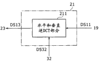
Shown in Fig. 5 B, the first inverse transformation part 21 has level and vertical inverse DCT part 211.211 couples of conversion coefficient DS11 that supply with from the first re-quantization part 19 of level and vertical inverse DCT part carry out the inverse DCT of level and vertical direction, and said inverse DCT is corresponding to the level in first conversion fraction 13 and the DCT of vertical direction.Level and vertical inverse DCT part 211 are exporting to Arithmetic Section 23 through carrying out the predictive error signal DS13 that inverse DCT obtains.
The second re-quantization part 20 is configured to carry out and the corresponding re-quantization of quantification that in second quantized segment 16, carries out.For example, as shown in Figure 6, the second re-quantization part 20 comprises mode selection switch 200 and the first incline direction pattern re-quantization part 201-the 6th incline direction pattern re-quantization part 206.
201 pairs of the first incline direction pattern re-quantization parts through the quantized data DS6 that mode selection switch 200 is supplied with carry out with second quantized segment 16 in the corresponding re-quantization of quantification of the first incline direction pattern quantization part 161.In addition, the first incline direction pattern re-quantization part 201 is according to the transform block set information DS32 that supplies with from transform block setting section 32, the quantized data in re-quantization each transform block corresponding with the transform block of second quantized segment 16.The first incline direction pattern re-quantization part 201 is exporting to the second inverse transformation part 22 through carrying out the conversion coefficient DS12 that re-quantization obtains.In addition, second to the 6th incline direction pattern re-quantization part 202-206 is the quantized data DS6 of re-quantization supply similarly, exports to the second inverse transformation part 22 to consequent conversion coefficient DS12.Thereby the second re-quantization part 20 is carried out the re-quantization consistent with the quantification of second quantized segment 16.
The second inverse transformation part 22 is configured to carry out and the corresponding inverse DCT of DCT that in second conversion fraction 14, carries out.For example, as shown in Figure 7, the second inverse transformation part 22 comprises mode selection switch 220 and the first incline direction pattern inverse DCT part, 221 to the 6th incline direction pattern inverse DCT parts 226.
The conversion coefficient DS12 that 221 pairs of the first incline direction pattern inverse DCT parts are supplied with through mode selection switch 220, carry out with second conversion fraction 14 in the corresponding inverse DCT of DCT of the first incline direction pattern DCT part 141.The first incline direction pattern inverse DCT part 221 is carried out the inverse DCT of the conversion coefficient in each transform block corresponding with the transform block of second conversion fraction 14 according to the transform block set information DS32 that supplies with from transform block setting section 32.The first incline direction pattern inverse DCT part 221 is exporting to Arithmetic Section 23 through carrying out the predictive error signal DS14 that inverse DCT obtains.In addition, the inverse DCT of the conversion coefficient DS12 that second to the 6th incline direction pattern inverse DCT part 222-226 supplies with is similarly exported to Arithmetic Section 23 to consequent predictive error signal DS14 then.Thereby, the second inverse transformation part 22 carry out in second conversion fraction 14 with the corresponding inverse DCT of prediction direction corresponding D CT.
The reference image signal DS15 that is kept in the reference memory 24 is provided for predicted portions 25 and reference picture rim detection part 31.
Reference picture rim detection part 31 is utilized the picture signal that is kept at the coding adjacent block in the reference memory 24; Detect the edge, export to transform block setting section 32 to the index DS31 of the intensity (steepness of variable density) at the position at indication edge and edge then.
Transform block setting section 32 is estimated the continuity as the edge in the sub-piece of coded object according to from the index DS31 of reference picture rim detection part 31 supplies and the prediction mode information D S20 that supplies with from predicted portions 25.Transform block setting section 32 is cut apart the sub-piece as coded object according to estimated result, the transform block in setting orthogonal transform and quantizing, and the transform block set information DS32 of the transform block of generation indicative of settings.Transform block setting section 32 is exported to first conversion fraction, 13, the second conversion fractions, 14, the first quantized segments 15 to the transform block set information DS32 that generates; Second quantized segment, 16, the first re-quantization parts, 19, the second re-quantization parts 20; The first inverse transformation part 21 and the second inverse transformation part 22.
[operation of 1-2. image encoding apparatus]
The operation of explanation image encoding apparatus below.With regard to the luminance signal in the infra-frame prediction of system H.264/AVC, shown in Fig. 8 A, in the coded object frame, set a plurality of macro blocks.Fig. 8 B representes to have the macro block of 16 sub-block of 4 * 4 pixels.Fig. 8 C representes to have the macro block of 4 sub-block of 8 * 8 pixels.Fig. 8 D representes to have the macro block of 1 sub-block of 16 * 16 pixels.
In system H.264/AVC, set 4 kinds of modes, that is, prediction mode 0-3 is as the prediction mode of 16 * 16 sub-block of pixels.In addition, set 9 kinds of modes, that is, prediction mode 0-8 is as the prediction mode of 8 * 8 sub-block of pixels.In addition, set 9 kinds of modes, that is, prediction mode 0-8 is as the prediction mode of 4 * 4 sub-block of pixels.
Fig. 9 helps pixel a-p that explanation belongs to 4 * 4 sub-block of pixels with in the adjacent block of left side, upper left side, upside and the upper right side of said sub-piece, the diagrammatic sketch of the position relation between the pixel A-M of contiguous said sub-piece.
Figure 10 A-10I representes in the infra-frame prediction, about the prediction mode of 4 * 4 pixels.Incidentally, the indication of the arrow among Figure 10 A-10I prediction direction.Figure 10 A representes prediction mode 0 (vertically).Prediction mode 0 is according to the reference pixel A-D of adjacency on the vertical direction, generation forecast value.Figure 10 B representes prediction mode 1 (level).Shown in arrow, prediction mode 1 is according to the reference pixel I-L of adjacency on the horizontal direction, generation forecast value.Figure 10 C representes prediction mode 2 (DC).Prediction mode 2 is according among 13 reference pixel A-M, in the reference pixel A-D and the I-L of the vertical direction and the horizontal direction adjacency of piece, generation forecast value.
Figure 10 D representes prediction mode 3 (left side is the diagonal angle down).Prediction mode 3 is according among 13 reference pixel A-M, continuous in the horizontal direction reference pixel A-H, generation forecast value.Figure 10 E representes prediction mode 4 (diagonal).Prediction mode 4 is according among 13 reference pixel A-M, reference pixel A-D and the I-M adjacent with the piece of being discussed, generation forecast value.Figure 10 F representes prediction mode 5 (vertically taking over).Prediction mode 5 is according among 13 reference pixel A-M, reference pixel A-D and the I-M adjacent with the piece of being discussed, generation forecast value.
Figure 10 G representes prediction mode 6 (level on the lower side).The same with prediction mode 5 as prediction mode 4, prediction mode 6 is according among 13 reference pixel A-M, reference pixel A-D and the I-M adjacent with the piece of being discussed, generation forecast value.Figure 10 H representes prediction mode 7 (vertically taking back).Prediction mode 7 is according among 13 reference pixel A-M, in the upside of the piece of being discussed adjacent 4 reference pixel A-D and 3 reference pixel E-G after said 4 reference pixel A-D, generation forecast value.Figure 10 I representes prediction mode 8 (level on the upper side).Prediction mode 8 is according among 13 reference pixel A-M, adjacent 4 reference pixel I-L in the left side of the piece of being discussed, generation forecast value.
When information converting DS40 indicated the prediction mode of horizontal direction and vertical direction, processing selecting switch 12 offered first to predictive error signal DS2 and changes part 13, so that carries out the DCT of horizontal direction and vertical direction.In addition, when information converting DS40 indication incline direction prediction mode, processing selecting switch 12 offers second conversion fraction 14 to predictive error signal DS2, so that carries out one dimension DCT along prediction direction.
When information converting DS40 indicates the prediction mode of horizontal direction and vertical direction; Processing selecting switch 18 offers the first re-quantization part 19 to quantized data DS5, the corresponding re-quantization and corresponding inverse transformation of quantized data experience that obtains with DCT and the quantification that causes through horizontal direction and vertical direction.When information converting DS40 indication incline direction prediction mode; Processing selecting switch 18 offers the second re-quantization part 20 to quantized data DS6, to cause the corresponding re-quantization and corresponding inverse transformation of quantized data experience that obtains through one dimension DCT and quantification along incline direction.
Explanation makes the judgement of the maximized prediction mode of code efficiency below.Predicted portions 25 is carried out encoding process according to each prediction mode, and judges that making the minimum prediction mode of coding cost that obtains through encoding process is best mode.Specifically, utilize equality (1) calculation code cost K, make the minimum prediction mode of coding cost K be set to best mode.
K=SAD+λ×OH ...(1)
Wherein mistake difference SAD is used in the prediction image signal of the Forecasting Methodology generation that defines in the prediction mode and the absolute value of the difference between the received image signal; Side information OH is the quantity of various information essential when using said prediction mode, and coefficient lambda is a Lagrange's multiplier.
In addition; The judgement of best mode is not limited to utilize the situation of the absolute value of side information and difference; Can only utilize mode information on the contrary; Perhaps only utilize the absolute of predictive error signal and judge said mode, perhaps can use Hadamard conversion or the approximate value that obtains through carrying out these each item information.In addition, can utilize the activity of input picture, obtain coding cost K, perhaps can utilize quantization scale to obtain the coding cost.
Also can utilize equality (2), calculation code cost K.
K=D+λ×R ...(2)
The square error between coding distortion D representing input images signal and the local decode picture signal wherein, the value of code R estimate that with tentative coding coefficient lambda is the constant of confirming according to quantization parameter.
When utilizing equality (2) calculation code cost, image encoding apparatus 10 needs the entropy coding and the local decode (comprising re-quantization and inversion process) of every kind of mode.Thereby, although circuit scale is increased, but accurate value that can use code and accurate coding distortion, thereby can make code efficiency remain on higher level.
Explanation is as the method along the one dimension DCT of prediction direction below, the DCT that in system H.264/AVC, carries out.Make that X is a received image signal, T is the transformation matrix of 4 * 4 sub-block of pixels, according to equality (3), obtains conversion coefficient C.
C=T·X·T
t ...(3)
Wherein
That is,, make the one dimension DCT of received image signal experience horizontal direction, afterwards through utilizing the transposed matrix T of transformation matrix T through utilizing transformation matrix T
t, make received image signal experience the one dimension DCT of vertical direction.This operation also is applicable to 8 * 8 sub-block of pixels.
Subsequently; Among 9 kinds of prediction mode for the infra-frame prediction that in system H.264/AVC, defines; Remove prediction mode 0 (vertically), the prediction mode along 6 directions that these three kinds of prediction mode of prediction mode 1 (level) and prediction mode 2 (DC) are outer is carried out the DCT along prediction direction.
Explanation is carried out along the situation of the DCT of prediction direction for 4 * 4 sub-block of pixels shown in Fig. 9 below.With regard to prediction mode 3, along prediction direction, the pixel in the sub-piece is divided into seven groups (a), (b, e), (c, f, i), (d, g, j, m), (h, k, n), (l, o) with (p).
Figure 11 A representes wherein to carry out the combination of the pixel string of one dimension DCT.Make F that (u) is conversion coefficient, (j m), carries out fundamental length and is 4 one dimension DCT for d, g to the pixel string in the diagonal that is present in 4 * 4 block of pixels.
The conversion coefficient F (u) of equality (4) expression when fundamental length is " N ".
When (j when m) obtaining conversion coefficient F (u), through utilizing fundamental length " N=4 ", and utilizes " f (0)=d, f (1)=g, f (2)=j and f (3)=m ", carries out the computing of equality (4), can obtain conversion coefficient F (u) for d, g for the pixel string.
When (c, f when i) obtaining conversion coefficient F (u), through utilizing fundamental length " N=3 ", and utilize " f (0)=c, f (1)=f and f (2)=i ", carry out the computing of equality (4), can obtain conversion coefficient F (u) for the pixel string.
(b e), utilizes the pixel that makes up each other according to the mode of turning back, and obtains conversion coefficient F (u) for pixel (a) and pixel string.In this case, through utilizing fundamental length " N=3 ", and utilize " f (0)=b, f (1)=e and f (2)=a " perhaps " f (0)=e, f (1)=b and f (2)=a ", carry out the computing of equality (4), can obtain conversion coefficient F (u).
Figure 11 B representes wherein under the situation not according to the mutual packed-pixel of the mode of turning back, to carry out the situation of one dimension DCT.(j is m) with (c, f i), carry out the similar one dimension DCT with the one dimension DCT of Figure 11 A for d, g for the pixel string.Under the situation not according to the mutual packed-pixel of the mode of turning back, (b e) and pixel (a), carries out one dimension DCT for the pixel string respectively.Specifically, when (b when e) obtaining conversion coefficient F (u), through utilizing fundamental length " N=2 ", and utilizes " f (0)=b and f (1)=e ", carries out the computing of equality (4), can obtain conversion coefficient F (u) for the pixel string.When obtaining conversion coefficient F (u) for pixel (a), through utilizing fundamental length " N=1 ", and utilize " f (0)=a ", carry out the computing of equality (4), can obtain conversion coefficient F (u).
Figure 11 C representes that wherein (c, f is i) with (e b) and under the situation of pixel (a), carries out the situation of one dimension DCT make up all pixel strings each other according to the mode of turning back.(j m), carries out the similar one dimension DCT with the one dimension DCT of Figure 11 A for d, g for the pixel string.(c, f is i) with (e b), and pixel (a), carries out one dimension DCT under according to the situation of the mutual packed-pixel of the mode of turning back for the pixel string.Specifically, when for pixel string (c, f, i, e; B when a) obtaining conversion coefficient F (u), through utilizing fundamental length " N=6 ", and utilizes " f (0)=c, f (1)=f; f (2)=i, f (3)=e, f (4)=b and f (5)=a " perhaps " f (0)=i, f (1)=f, f (2)=c; f (3)=b, f (4)=e and f (5)=a ", carries out the computing of equality (4), can obtain conversion coefficient F (u).Incidentally, (h, k is n) with (l o), and pixel (p), can obtain conversion coefficient F (u) in a comparable manner for the pixel string.
With regard to prediction mode 4, can think that in prediction mode 4 prediction direction of prediction mode 3 is by horizontal inversion, so can be according to carrying out the DCT computing with prediction mode 3 similar modes.
The DCT operation method corresponding with prediction mode 5-8 is described below.With regard to prediction mode 5, the pixel in the sub-piece along prediction direction be divided into five groups of pixel strings (a, e, j, n), (b, f, k, o), (c, g, l, p), (i, m) with (d, h).Figure 12 A representes it is used the combination of the character string of one dimension DCT.When (j when n) obtaining conversion coefficient F (u), through utilizing fundamental length " N=4 ", and utilizes " f (0)=a, f (1)=e, f (2)=j and f (3)=n ", carries out the computing of equality (4), can obtain conversion coefficient F (u) for a, e for the pixel string.(k is o) with (l p), through carrying out similar computing, can obtain conversion coefficient F (u) for c, g for b, f for the pixel string.
When (i when m) obtaining conversion coefficient F (u), through utilizing fundamental length " N=2 ", and utilizes " f (0)=i and f (1)=m ", carries out the computing of equality (4), can obtain conversion coefficient F (u) for the pixel string.(d h), through carrying out similar computing, can obtain conversion coefficient F (u) for the pixel string.
The method of in addition, carrying out one dimension DCT under according to the situation of the mutual packed-pixel of the mode of turning back can be counted as another example of the DCT computing corresponding with prediction mode 5.Figure 12 B is illustrated in this case, and it is used the combination of the pixel string of one dimension DCT.(k o), carries out the similar one dimension DCT with above-mentioned one dimension DCT for b, f to the pixel string.For the pixel string (a, e, j, n) with (m, i), and the pixel string (p, l, g, c) with (d h), carries out one dimension DCT under according to the situation of the mutual packed-pixel of the mode of turning back.Specifically, when for pixel string (a, e, j, n; M when i) obtaining conversion coefficient F (u), through utilizing fundamental length " N=6 ", and utilizes " f (0)=a, f (1)=e; f (2)=j, f (3)=n, f (4)=m and f (5)=i ", carries out the computing of equality (4), can obtain conversion coefficient F (u).In addition, (g is c) with (d h), through carrying out similar computing, can obtain conversion coefficient F (u) for p, l for the pixel string.
With regard to prediction mode 6-8, can think that in prediction mode 6-8, the prediction direction of prediction mode 5 is rotated or reverses, so can carry out the DCT computing according to the mode similar with prediction mode 5.
In addition, as for block size as the sub-piece of coded object, the little piece of also available ratio 4 * 4 block of pixels, perhaps big than 4 * 4 block of pixels piece carries out encoding process as sub-piece.In addition, the DCT computing is not limited to real number DCT computing, and on the contrary, also available integer arithmetic carries out DCT.
Figure 13 and Figure 14 are the flow charts of the operation of the image encoding apparatus 10 among first embodiment.Incidentally, suppose the prediction mode 0-8 shown in Figure 10 A-10I is set in encoding process.
At step ST1, image encoding apparatus 10 obtains input picture.Image encoding apparatus 10 obtains received image signal DS1, begins the coding in each macro block or the every pair of macro block then.
At step ST2, image encoding apparatus 10 carries out the initialization relevant with sub-piece.Image encoding apparatus 10 bundle piece index sub_blk are initialized to " sub_blk=0 ", set maximum sub-piece simultaneously and count MAX_SUB_BLK.Image encoding apparatus 10 gets into step ST3 subsequently.
At step ST3, image encoding apparatus 10 is declared stator block index sub_blk and whether is counted MAX_SUB_BLK less than the sub-piece of maximum.When group piece index sub_blk counts MAX_SUB_BLK less than the sub-piece of maximum, in the sub-piece in macro block, there is the sub-piece that waits to encode, so image encoding apparatus 10 gets into step ST4.When group piece index sub_blk is not less than maximum sub-piece and counts MAX_SUB_BLK, in the sub-piece in macro block, there is not the sub-piece that waits to encode, so image encoding apparatus 10 gets into step ST22.
At step ST4, image encoding apparatus 10 carries out the initialization relevant with prediction mode.Image encoding apparatus 10 is initialized to " mode_idx=0 " to prediction mode index mode_idx, and sets maximum optional mode and count MAX_MODE.For example, when 9 kinds of prediction mode are set, in other words during prediction mode 0-8, " MAX_MODE=9 ".Incidentally, prediction mode index mode_idx=0 is corresponding to prediction mode 0.Similarly, index mode_idx=1-8 is corresponding to prediction mode 1-8.
At step ST5, image encoding apparatus 10 judges whether prediction mode index mode_idx counts MAX_MODE less than maximum mode.When prediction mode index mode_idx counts MAX_MODE less than maximum mode, also do not attempt all infra-frame prediction modes, so image encoding apparatus 10 gets into step ST6.When prediction mode index mode_idx is not less than maximum mode and counts MAX_MODE, all infra-frame prediction modes had been attempted, so image encoding apparatus 10 gets into step ST21.
At step ST6, image encoding apparatus 10 is set information converting trans_idx.Image encoding apparatus 10 is set information converting trans_idx according to the value of prediction mode index mode_idx.When prediction mode index mode_idx indication incline direction prediction mode (prediction mode 3-8), image encoding apparatus 10 is set information converting trans_idx for " trans_idx=0 ".Image encoding apparatus 10 gets into step ST7 subsequently.When prediction mode index mode_idx indicated non-incline direction prediction mode (prediction mode 0-2), image encoding apparatus 10 was set information converting trans_idx for " trans_idx=1 ".Image encoding apparatus 10 gets into step ST7 subsequently.
At step ST7, image encoding apparatus 10 is according to the prediction mode of index mode_idx, the generation forecast picture signal.Image encoding apparatus 10 utilizes the picture signal of reference picture, with the prediction mode of index mode_idx indication, generation forecast picture signal.Image encoding apparatus 10 gets into step ST8 subsequently.
At step ST8, image encoding apparatus 10 generation forecast error signals.Image encoding apparatus 10 is through calculating the prediction image signal DS18 among the prediction image signal DS18 under the prediction mode of index mode_idx, generate, and the difference between the picture signal DS1 of input, generation forecast error signal DS2.Image encoding apparatus 10 gets into step ST9 subsequently.
At step ST9, image encoding apparatus 10 carries out rim detection.Image encoding apparatus 10 utilizes the picture signal (picture signal of the adjacent block of coding) of the reference picture of preserving, and detects the edge, and the index DS31 of the intensity at the position at the said edge of generation indication and said edge.Image encoding apparatus 10 gets into step ST10 subsequently.
At step ST10, image encoding apparatus 10 is set transform block.Image encoding apparatus 10 is according to the direction of the prediction mode of the index DS31 of the intensity at position and the edge at indication edge and index of reference mode_idx indication, and estimation is as the continuity at the edge in the sub-piece of coded object.In addition, image encoding apparatus 10 is set transform block according to estimated result, and generating transformation piece set information DS32.Image encoding apparatus 10 gets into step ST11 subsequently.
At step ST11; Image encoding apparatus 10 judges that whether prediction mode index mode_idx count mode_direction less than the minimum mode as the incline direction prediction mode of the minimum value of the mode number of incline direction prediction mode, and perhaps whether information converting is " trans_idx=1 ".The situation of counting mode_direction less than minimum mode at prediction mode index mode_idx, and/or information converting is under the situation of " trans_idx=1 ", image encoding apparatus 10 gets into step ST12.Otherwise image encoding apparatus 10 gets into step ST14.
At step ST12, image encoding apparatus 10 carries out level and vertical DCT.Image encoding apparatus 10 gets into step ST13 subsequently.At step ST13, image encoding apparatus 10 carries out level and vertical quantification.Image encoding apparatus 10 gets into step ST16 subsequently.Image encoding apparatus 10 for example changes to first conversion fraction, 13 1 sides to processing selecting switch 12, thereby utilizes first conversion fraction 13 and first quantized segment 15, carries out DCT and quantification.
At step ST14, image encoding apparatus 10 carries out incline direction pattern DCT.Image encoding apparatus 10 gets into step ST15 subsequently.At step ST15, image encoding apparatus 10 carries out the incline direction pattern quantization.Image encoding apparatus 10 gets into step ST16 subsequently.Image encoding apparatus 10 for example changes to second conversion fraction, 14 1 sides to processing selecting switch 12.In addition, image encoding apparatus 10 is according to prediction mode index mode_idx, changes mode selection switch 140 and the mode selection switch 160 in second quantized segment 16 in second conversion fraction 14.Image encoding apparatus 10 utilizes incline direction pattern DCT part and the incline direction pattern quantization part corresponding with prediction direction through changing switch according to index mode_idx, carries out DCT and quantification.
At step ST16, image encoding apparatus 10 carries out entropy coding.10 couples of quantized data DS5 of image encoding apparatus and DS6, prediction mode information DS20, and information converting DS40 carries out entropy coding.Image encoding apparatus 10 gets into step ST17 subsequently.
At step ST17, image encoding apparatus 10 is preserved the coding cost of prediction mode.Image encoding apparatus 10 is the value of assessing the cost K as stated, and preserves the value at cost K that calculates.Image encoding apparatus 10 gets into step ST18 subsequently.
At step ST18, image encoding apparatus 10 judges whether information converting trans_idx is " trans_idx=0 ".When information converting trans_idx was " trans_idx=0 ", image encoding apparatus 10 got into step ST19.When information converting trans_idx was not " trans_idx=0 ", image encoding apparatus 10 got into step ST20.
At step ST19, image encoding apparatus 10 adds " 1 " to information converting trans_idx, to set new information converting trans_idx.Image encoding apparatus 10 returns step ST11 subsequently.
At step ST20, image encoding apparatus 10 adds " 1 " to prediction mode index mode_idx, to set new index mode_idx.Image encoding apparatus 10 returns step ST5 subsequently.
Through the processing that repeats similarly to begin from step ST5, might prediction mode calculation code cost according to the institute of sub-piece.
Afterwards, when image encoding apparatus 10 in step ST5, judge that image encoding apparatus 10 got into step ST21 when prediction mode index mode_idx was not less than maximum mode and counts MAX_MODE.At step ST21, image encoding apparatus 10 bundle piece index sub_blk add " 1 ", to set new index sub_blk.Image encoding apparatus 10 returns step ST3 subsequently.
In step ST3, declare stator block index sub_blk when image encoding apparatus 10 and be not less than maximum sub-piece and count MAX_SUB_BLK, so when getting into step ST22, image encoding apparatus 10 is written into the data about the best mode of every sub-block.Image encoding apparatus 10 compares the coding cost (said coding cost obtains about every sub-block) of corresponding manner each other, and is written into the data about the best mode in every sub-block.Image encoding apparatus 10 gets into step ST23 subsequently.In addition, image encoding apparatus 10 generates the prediction mode information D S20 of indication best mode.
At step ST23, image encoding apparatus 10 multiplexed with send out the coded data of encoding and obtaining according to best mode through in macro block.In addition, image encoding apparatus 10 entropy coding prediction mode information D S20, that is, and the index mode_idx of best mode and information converting DS40, that is, and information converting trans_idx, and be included in the information of entropy coding in the coded data.
Following with reference to figure 15A-15F, the operation of description references Image Edge-Detection part 31.Figure 15 A representes that the size as the sub-piece of coded object is the situation of 16 * 16 pixels.Be a vertical row and the signal of a horizontal line that is kept at the adjacent block of the coding in the reference memory 24 with the part of shadow representation among Figure 15 A.Reference picture rim detection part 31 detects the edge of the signal of each in the said adjacent vertical row represented with dash area and the said adjacent horizontal line, and the index of the intensity at the position at output indication edge and edge.For example, reference picture rim detection part 31 is used one dimension Sobel filtering, and output is through using the signal that one dimension Sobel filtering obtains.Has information through using signal that one dimension Sobel filtering obtains about the intensity at the position at edge and edge.Represented among Figure 15 B through using the image of the signal that one dimension Sobel filtering obtains.Incidentally, consider the succinct of explanation, for simplicity, represent signal, represent the edge with the position that black is represented as multi-valued signal with white and black.The form of the index of the intensity at position and the edge at indication edge can not be through using the form of the signal that said filtering obtains.For example, can obtain to indicate the existence whether mark at edge and take only to indicate the data of form of point of the intensity at said edge in the position at said edge.In addition, can use any means to calculate the index of intensity at position and the edge at indication edge, as long as can obtain said index.For example, Prewitt filtering or Laplician filtering be can use, mathematics or physical method except that filtering perhaps can be used.
In addition, though in Figure 15 A and 15B, obtain indication and index, but be not limited thereto as the intensity at the position at the edge of the signal of each in the adjacent said vertical row of the sub-piece of coded object and the horizontal line and edge.Shown in Figure 15 C and 15D, can use multirow.In addition, though the varying in size when 16 * 16 pixels big or small of group piece, but also handle like the application class.For example, shown in Figure 15 E and 15F, also can like the situation application class of 8 * 8 pixels, handle.
Following with reference to figure 16A-16D, the operation of transform block setting section 32 is described.Figure 16 A representes that the block size as the sub-piece of coded object is the situation of 16 * 16 pixels.Transform block setting section 32 is cut apart sub-piece according to the information and the prediction mode information D S20 of the intensity at position of indicating the edge and edge, and sets transform block.Transform block setting section 32 is estimated in the continuity as the edge in the sub-piece of coded object according to the position and the prediction mode information D S20 at edge.For example, transform block setting section 32 is estimated to use the edge that Sobel filtering detects through vertical row and horizontal line to adjacent block, on the prediction direction with prediction mode information D S20 indication, is continuous, shown in Figure 16 A.Incidentally, Figure 16 A representes the estimated result of the edge continuity when prediction mode information D S20 indication prediction mode 5.In addition, in Figure 16 A, considered the succinct of explanation, for simplicity, represented multi-valued signal, black part representative edge edge with white and black.
In addition; Shown in Figure 16 B; When the position at the edge that detects in the multirow in can be used on adjacent each piece and the direction of intensity estimated edge,, estimate be considered to there is the edge on the more suitable direction according to the direction at the edge in prediction mode and adjacent each piece.For example, the reliability of the direction at the edge in the reliability of prediction mode and adjacent each piece is converted into numerical value, and adopts the higher person in the numerical value.Reliability comprises when the edge has higher intensity to the conversion of numerical value, makes the higher method of reliability at the edge in the adjacent block.When numerical value surpasses threshold value, for example adopt the direction at the edge in the adjacent block.Figure 16 representes wherein to adopt the direction at the edge in adjacent each piece, rather than adopts the example of prediction mode 5.
Subsequently, consider the continuity at the edge of estimation, transform block setting section 32 is cut apart the sub-piece as coded object, and sets the transform block that is used for orthogonal transform.In this case, from the viewpoint of code efficiency, desirable is to be divided into a plurality of transform blocks to the sub-piece as coded object, and the zone that does not consequently cover the edge is big as much as possible.Thereby shown in Figure 16 C, transform block setting section 32 levels and vertical segmentation are as the sub-piece of coded object, so that the border between the piece after cutting apart does not comprise the edge.For example, transform block setting section 32 is found out the end of continuous boundary, and confirms the border cut apart according to the mode that contacts with said end.Transform block setting section 32 is being set at the unit of orthogonal transform as each piece after the cutting apart of transform block, and generates the transform block set information DS32 of indication transform block.
When cutting apart sub-piece, possibly exist wherein to detect a plurality of edges, the mode that can not cover the edge according to the border of transform block is cut apart the situation of sub-piece.In this case, transform block setting section 32 confirms not drop on the priority orders at the edge on the block boundary according to the index of the intensity at indication edge.For example, the high energy signals that obtains to the filtering that utilizes the Sobel filter of transform block setting section 32 is given higher priority.Can be relatively or confirm the order of priority utterly.So confirm the order of priority, and cut apart, so that the edge of high priority can not drop on the border between the transform block.In addition, sub-piece not necessarily needs to cut apart along level and vertical direction simultaneously, can cut apart along level or vertical direction on the contrary, perhaps can not cut apart.Piece after further cutting apart to layering perhaps can be divided into a plurality of cut apart in identical layer.In addition, the big I of the transform block after cutting apart is confined to take into account the compatibility with common coded system, is the size of 2 n power.
In addition, when from reference picture rim detection part 31 during with different form output signal, concerning transform block setting section 32, as long as according to said signal, according to the continuity of the similar principle estimated edge of said process, and it is just passable to set transform block.
The size of sub-piece is not limited to 16 * 16 pixel sizes, on the contrary, for other sub-block size, processing that can applications similar.For example, like institute among Figure 16 D not, can be to the processing of the sub-block size applications similar of 8 * 8 pixels.
Figure 17 representes to utilize reference picture rim detection part 31 and transform block setting section 32, sets the process of transform block.At step ST31, reference picture rim detection part 31 obtains indication and index as the intensity at the position at the edge in the adjacent reference picture of the sub-piece of coded object and said edge.Processing subsequent gets into step ST32.
At step ST32, transform block setting section 32 is estimated the continuity as the edge in the sub-piece of coded object according to the index of the intensity at position of indicating the edge and edge and the prediction mode information D S20 that obtains from predicted portions 25.Processing subsequent gets into step ST33.
At step ST33, transform block setting section 32 is considered continuity and the intensity at edge at the edge of estimation, sets transform block.
In transform block setting section 32, set after the transform block like this, first conversion fraction 13, the first quantized segments, 15, the first re-quantization parts 19 and the first inverse transformation part 21 are carried out DCT, quantification, re-quantization and inverse DCT in the transform block of each setting.
In addition, second conversion fraction 14, the second quantized segments, 16, the second re-quantization parts 20 and the second inverse transformation part 22 are carried out DCT along the prediction direction corresponding with prediction mode information D S20 in the transform block of each setting, quantize re-quantization and inverse DCT.Figure 18 A-18E representes the block size that its neutron piece has 8 * 8 pixels, and sub-piece is divided into 4 parts, and said 4 parts are set to the situation (shown in Figure 16 D) of transform block.For example, the sub-piece of 8 * 8 pixels shown in Figure 18 A is divided into 5 * 6 pixels, 3 * 6 pixels, and the transform block of 5 * 2 pixels and 3 * 2 pixels is shown in Figure 18 B-18E.In addition, suppose that prediction mode is a mode 5.In this case, scan the signal in each piece, and consider that the correlation that is present in the vertical bank direction carries out DCT.For example, carry out the scanning shown in the arrow among Figure 18 B-18E, and carry out DCT according to the respective number of contiguous pixels.
Incidentally, orthogonal transform is not limited to DCT, can be wavelet transformation for example on the contrary, and the Hadamard conversion is perhaps through being reduced to the conversion that integer precision obtains to wavelet transformation and Hadamard conversion.As long as use the method for the orthogonal transform be suitable for also adopting quantification just much of that.
[structure of 1-3. image decoding apparatus]
Explanation is to the coded data decoded image decoding device of image encoding apparatus 10 generations below.
Figure 19 representes the structure of the image decoding apparatus 50 among first embodiment.Image decoding apparatus 50 comprises entropy decoded portion 51, processing selecting switch 52, the first re-quantization parts 53, the second re-quantization parts 54, the first inverse transformation parts 55, the second inverse transformation parts 56, Arithmetic Section 57, reference memory 58 and predicted portions 60.Image decoding apparatus 50 also comprises reference picture rim detection part 71, transform block setting section 72 and decoding control section 80.
51 couples of encoded data D SC that receive as input of entropy decoded portion carry out the entropy decoding.Entropy decoded portion 51 carry out with entropy coding part 17 in image encoding apparatus 10 in the corresponding entropy decoding of entropy coding carried out.Entropy decoded portion 51 is exporting to processing selecting switch 52 through carrying out quantized data DS51 and information converting DS52 (corresponding to DS40) that the entropy decoding obtains.Entropy decoded portion 51 is also exported to predicted portions 60 to the prediction mode information D S53 (corresponding to DS20) that obtains through the entropy decoding.
Processing selecting switch 52 switches according to the information converting DS52 that supplies with from entropy decoded portion 51, thereby exports to the first re-quantization part 53 or the second re-quantization part 54 to quantized data DS51.
The first re-quantization part 53 be according to image encoding apparatus 10 in the first re-quantization part, 19 similar modes constitute.The quantized data DS51 that the treated selector switch 52 of the first re-quantization part, 53 re-quantizations is supplied with.In addition, the first re-quantization part 53 is according to the transform block set information DS76 that supplies with from transform block setting section 72, the quantized data in each transform block of re-quantization.The first re-quantization part 53 is exporting to the first inverse transformation part 55 through carrying out the conversion coefficient DS54 that re-quantization obtains.
The first inverse transformation part 55 be according to image encoding apparatus 10 in the first inverse transformation part, 21 similar modes constitute.The first inverse transformation part 55 is according to the transform block set information DS76 that supplies with from transform block setting section 72, to the conversion coefficient DS54 application level direction of supplying with from the first re-quantization part 53 in each transform block and the inverse DCT of vertical direction.The first inverse transformation part 55 is exporting to Arithmetic Section 57 through carrying out the predictive error signal DS56 that inverse DCT obtains.
The second re-quantization part 54 be according to image encoding apparatus 10 in the second re-quantization part, 20 similar modes constitute.The second re-quantization part 54 in the incline direction pattern re-quantization part corresponding with the prediction direction of information converting DS52 indication, the quantized data DS51 of treated selector switch 52 supplies of re-quantization.In addition, the second re-quantization part 54 is according to the transform block set information DS76 that supplies with from transform block setting section 72, the quantized data in each transform block of re-quantization.The second re-quantization part 54 is exported to the second inverse transformation part 56 through carrying out the conversion coefficient DS55 that re-quantization obtains.
The second inverse transformation part 56 be according to image encoding apparatus 10 in the second inverse transformation part, 22 similar modes constitute.The second inverse transformation part 56 is carried out from the inverse DCT of the conversion coefficient DS55 of the second re-quantization part, 54 supplies in the incline direction pattern inverse DCT part corresponding with the prediction direction of information converting DS52 indication.In addition, the second inverse transformation part 56 is carried out the inverse DCT in each transform block according to the transform block set information DS76 that supplies with from transform block setting section 72.The second inverse transformation part 56 is exported to Arithmetic Section 57 through carrying out the predictive error signal DS57 that inverse DCT obtains.
The picture signal DS58 that is kept in the reference memory 58 is provided for predicted portions 60 and reference picture rim detection part 71.In addition, be kept at reference image signal in the reference memory 58 as output image signal DS59, from image decoding apparatus 50 by order output.
Reference picture rim detection part 71 be according to image encoding apparatus 10 in reference picture rim detection part 31 similar modes constitute.Reference picture rim detection part 71 is utilized the picture signal that is kept at the decoding adjacent block in the reference memory 58, detects the edge, and exports to transform block setting section 72 to the index DS75 of the intensity at the position at indication edge and edge.
Transform block setting section 72 be according to image encoding apparatus 10 in transform block setting section 32 similar modes constitute.Transform block setting section 72 is estimated the continuity as the edge in the piece of decoder object according to from the index DS75 of reference picture rim detection part 71 supplies and the prediction mode information D S53 that supplies with from entropy decoded portion 51.Transform block setting section 72 is set the transform block that carries out inverse orthogonal transformation and re-quantization according to estimated result, and generates the transform block set information DS76 of indication transform block.Transform block setting section 72 is exported to first re-quantization part 53, the second re-quantization parts, 54, the first inverse transformation parts 55 and the second inverse transformation part 56 to the transform block set information DS76 that generates.
Decoding control section is divided 80 control commands sent in the processing etc. of decoding and coding data.
[operation of 1-4. diagram decoding device]
Figure 20 is the flow chart of the operation of the image decoding apparatus 50 among first embodiment.At step ST51, image decoding apparatus 50 obtains coded data.Image decoding apparatus 50 obtains encoded data D SC, begins the decoding in each macro block or the every pair of macro block.Image decoding apparatus 50 gets into step ST52 subsequently.
At step ST52, image decoding apparatus 50 carries out the entropy decoding.The variable-length code (VLC) of each sentence structure of image decoding apparatus 50 decoding and coding data DSC, thus quantized data DS51, information converting DS52 and prediction mode information D S53 reproduced.Image decoding apparatus 50 gets into step ST53 subsequently.
At step ST53, image decoding apparatus 50 carries out syntactic analysis.The data analysis sentence structure of image decoding apparatus 50 from obtaining through decoding.Image decoding apparatus 50 gets into step ST54 subsequently.
At step ST54, image decoding apparatus 50 carries out the initialization relevant with sub-piece.Image decoding apparatus 50 bundle piece index sub_blk are initialized to " sub_blk=0 ", set maximum sub-piece simultaneously and count MAX_SUB_BLK.Image decoding apparatus 50 gets into step ST55 subsequently.
At step ST55, image decoding apparatus 50 is declared stator block index sub_blk and whether is counted MAX_SUB_BLK less than the sub-piece of maximum.When group piece index sub_blk counts MAX_SUB_BLK less than the sub-piece of maximum, in each sub-block in macro block, there is the sub-piece that waits to decode, so image decoding apparatus 50 gets into step ST56.When group piece index sub_blk is not less than maximum sub-piece and counts MAX_SUB_BLK, in each sub-block in macro block, there is not the sub-piece that waits to decode, so image decoding apparatus 50 gets into step ST68.
At step ST56, image decoding apparatus 50 is written into index mode_idx and information converting trans_idx.Image decoding apparatus 50 extracts index mode_idx and information converting trans_idx from coded data.Image decoding apparatus 50 gets into step ST57 subsequently.
At step ST57, image decoding apparatus 50 generation forecast images.Image decoding apparatus 50 utilizes the picture signal of reference picture, that is, the picture signal of the decoding adjacent block of preservation is according to the prediction mode of index mode_idx indication, generation forecast picture signal DS61.Image decoding apparatus 50 gets into step ST58 subsequently
At step S58, image decoding apparatus 50 detection edges.Image decoding apparatus 50 utilizes the picture signal of the decoding adjacent block of preserving, and detects the edge, and the index DS75 of the intensity at the position at generation indication edge and edge.Image decoding apparatus 50 gets into step ST59 subsequently.
At step ST59, image decoding apparatus 50 is set transform block.Image decoding apparatus 50 is estimated the continuity as the edge in the sub-piece of decoder object according to the index DS75 of the intensity at position of indicating the edge and edge and the prediction direction of index mode_idx.In addition, image decoding apparatus 50 is cut apart sub-piece according to the estimated result of edge continuity, and sets transform block.Subsequent picture decoding device 50 gets into step ST60.
At step ST60; Image decoding apparatus 50 is judged prediction mode index mode_idx whether less than the minimum mode number mode_direction as the incline direction prediction mode of the minimum value of the mode number of incline direction prediction mode, and perhaps whether information converting is " trans_idx=1 ".Is under the situation of " trans_idx=1 " at prediction mode index mode_idx less than situation and/or the information converting of minimum mode number mode_direction, and image decoding apparatus 50 gets into step ST61.Otherwise image decoding apparatus 50 gets into step ST63.
At step ST61, image decoding apparatus 50 carries out level and vertical re-quantization.Image decoding apparatus 50 gets into step ST62 subsequently.At step ST62, image decoding apparatus 50 carries out level and vertical inverse DCT.Image decoding apparatus 50 gets into step ST65 subsequently.Image decoding apparatus 50 for example changes to the first re-quantization part, 53 1 sides to processing selecting switch 52, and utilizes the first re-quantization part 53 and the first inverse transformation part 55, carries out re-quantization and inverse DCT.
At step ST63, image decoding apparatus 50 carries out incline direction pattern re-quantization.Image decoding apparatus 50 gets into step ST64 subsequently.At step ST64, image decoding apparatus 50 carries out incline direction pattern inverse DCT.Image decoding apparatus 50 gets into step ST65 subsequently.Image decoding apparatus 50 for example changes to the second re-quantization part, 54 1 sides to processing selecting switch 52.Image decoding apparatus 50 is according to prediction mode index mode_idx; Change the mode selection switch in the second re-quantization part 54 and the second inverse transformation part 56; And utilization incline direction pattern re-quantization part and the incline direction pattern inverse DCT part corresponding with prediction direction, carry out re-quantization and inverse DCT.
At step ST65, image decoding apparatus 50 synthetic predicated error and predicted pictures.Image decoding apparatus 50 generates picture signal DS58 through addition prediction image signal DS61 and predictive error signal DS56 or predictive error signal DS57.Image decoding apparatus 50 gets into step ST66 subsequently.
At step ST66, image decoding apparatus 50 is kept at the picture signal DS58 that generates in the reference memory.Image decoding apparatus 50 is kept at the picture signal DS58 that generates in the reference memory 58.Image decoding apparatus 50 gets into step ST67 subsequently.
At step ST67, image decoding apparatus 50 bundle piece index sub_blk add " 1 ", to set new index sub_blk.Image decoding apparatus 50 returns step ST55 subsequently.
In addition, in step ST55, declare stator block index sub_blk when image decoding apparatus 50 and be not less than maximum sub-piece and count MAX_SUB_BLK, thereby when getting into step ST68, image decoding apparatus 50 output decoder images.Image decoding apparatus 50 outputs are kept at the picture signal in the reference memory 58, as the picture signal of decoded picture after the decoding of sub-piece is accomplished.
Thereby according to first embodiment, in image encoding apparatus 10, reference picture rim detection part 31 is carried out rim detection through being used for the coded object piece to the picture signal of reference picture.In addition, according to the result of rim detection, transform block setting section 3 partition encoding object pieces, the border between each piece after consequently cutting apart does not comprise the edge, and sets transform block.In addition, in each transform block, comprise the processing of orthogonal transform, and generate coded data by the encoding process part of formation such as first conversion fraction, 13, the second conversion fractions, 14, the first quantized segments, 15, the second quantized segments 16.In addition, in image decoding apparatus 50, reference picture rim detection part 71 is carried out rim detection through being used for the decoder object piece to the picture signal of reference picture.In addition, according to the result of rim detection, transform block setting section 72 is cut apart the decoder object piece, and the border between each piece after consequently cutting apart does not comprise the edge, and the setting transform block identical with the transform block of image encoding apparatus 10.In addition, in each transform block, comprise the processing of inverse orthogonal transformation, and generate picture signal by the decoding processing part of formation such as the first re-quantization part, 53, the second re-quantization parts, 54, the first inverse transformation parts, 55, the second inverse transformation parts 56.In addition,, consider edge continuity, set transform block according to the mode of infra-frame prediction.Cross over a plurality of transform blocks so can prevent continuous boundary, thereby improve subjective picture quality.In addition, do not comprise that the transform block at edge is increased, so that can improve energy accumulating.In addition, be used in the same operation of carrying out in image encoding apparatus and the image decoding apparatus, set transform block for identical size.Thereby even when the information about transform block is not included among the encoded data D SC, encoded data D SC also can be decoded, thereby can improve code efficiency.
< 2. second embodiment >
Second embodiment is described below.Above-mentioned first embodiment improves code efficiency through not being included in the transform block set information of the transform block of indication adaptive change in the coded data.But, image decoding apparatus need possess the transform block setting section, even so that when not comprising the transform block set information in the coded data, also can correctly carry out decoding processing.Thereby, in a second embodiment, with explaining wherein through tolerating the slight reduction of code efficiency, the situation of the structure of simplified image decoding device.
[structure of 2-1. image encoding apparatus]
Figure 21 representes the structure according to the image encoding apparatus 10a of second embodiment.Incidentally, in Figure 21, with according to the corresponding element of the element of the image encoding apparatus 10 of first embodiment with identical Reference numeral identification.
The prediction image signal DS18 of Arithmetic Section 11 through generating in the predicted portions 25 that from received image signal DS1, deducts explanation in the back calculates the predicated error of predicted picture with respect to input picture.Arithmetic Section 11 is exported to processing selecting switch 12 to the predictive error signal DS2 of indication predicated error.
Processing selecting switch 12 switches, thereby exports to first quantized segment 15 or second quantized segment 16 to predictive error signal DS2 according to the information converting DS40 that supplies with from coding control section 40.
First quantized segment 15 quantizes from the conversion coefficient DS3 of first conversion fraction, 13 outputs, and exports to entropy coding part 17a and processing selecting switch 18 to quantized data DS5.In addition, first quantized segment 15 quantizes the conversion coefficient DS3 in each transform block according to the transform block set information DS32 that supplies with from transform block setting section 32a.
The predictive error signal DS2 that 14 pairs of second conversion fractions are supplied with from processing selecting switch 12 use based on the DCT from the prediction direction of the prediction mode information D S20 of predicted portions 25.In addition, second conversion fraction 14 carries out DCT along prediction direction according to the transform block set information DS32 that supplies with from transform block setting section 32a in each transform block, export to second quantized segment 16 to consequent conversion coefficient DS4 then.
Second quantized segment 16 quantizes to export to entropy coding part 17a and processing selecting switch 18 to quantized data DS6 then from the conversion coefficient DS4 of second conversion fraction, 14 supplies along prediction direction according to the prediction mode information D S20 that supplies with from predicted portions 25.In addition, second quantized segment 16 quantizes the conversion coefficient DS4 in each transform block according to the transform block set information DS32 that supplies with from transform block setting section 32a.
The quantized data DS5 that entropy coding part 17a entropy coding is supplied with from first quantized segment 15, the quantized data DS6 that perhaps supplies with from second quantized segment 16.In addition, the prediction mode information D S20 that entropy coding part 17a entropy coding generates in predicted portions 25, the transform block set information DS32 of the transform block that information converting DS40 that in coding control section 40, generates and indication are set in transform block setting section 32a.Entropy coding part 17a output is through carrying out the encoded data D SC that entropy coding obtains.
Processing selecting switch 18 is according to the information converting DS40 that supplies with from coding control section 40; Select inverse transformation method; And a quantized data DS5 from first quantized segment 15 exports to the first re-quantization part 19 and exports to the second re-quantization part 20 to the quantized data DS6 from second quantized segment 16.
The quantized data DS5 that the treated selector switch 18 of the first re-quantization part, 19 re-quantizations is supplied with.In addition, the first re-quantization part 19 is according to the transform block set information DS32 that supplies with from transform block setting section 32a, the quantized data in re-quantization each transform block corresponding with the transform block of first quantized segment 15.The first re-quantization part 19 is exporting to the first inverse transformation part 21 through carrying out the conversion coefficient DS11 that re-quantization obtains.
The first inverse transformation part 21 is carried out inverse DCT along horizontal direction and vertical direction to the conversion coefficient DS11 that supplies with from the first re-quantization part 19, and is in the said inverse DCT and first conversion fraction 13, corresponding along the DCT of horizontal direction and vertical direction.In addition, the first inverse transformation part 21 is carried out the inverse DCT of horizontal direction and vertical direction according to the transform block set information DS32 that supplies with from transform block setting section 32a in each transform block.The first inverse transformation part 21 is exporting to Arithmetic Section 23 through carrying out the predictive error signal DS13 that inverse DCT obtains.
The quantized data DS6 that the treated selector switch 18 of the second re-quantization part, 20 re-quantizations is supplied with.The second re-quantization part 20 is carried out the re-quantization of the prediction direction corresponding with the prediction direction of second quantized segment 16 according to the prediction mode information D S20 from predicted portions 25.In addition, the second re-quantization part 20 is according to the transform block set information DS32 that supplies with from transform block setting section 32a, the quantized data in re-quantization each transform block corresponding with the transform block of second quantized segment 16.The second re-quantization part 20 is exporting to the second inverse transformation part 22 through carrying out the conversion coefficient DS12 that re-quantization obtains.
The second inverse transformation part 22 is carried out the inverse DCT of conversion coefficient DS12.The second inverse transformation part 22 is carried out the inverse DCT of the prediction direction corresponding with the prediction direction of second conversion fraction 14 according to the prediction mode information D S20 from predicted portions 25.In addition, the second inverse transformation part 22 is carried out the inverse DCT of the conversion coefficient in each transform block corresponding with the transform block of second conversion fraction 14 according to the transform block set information DS32 that supplies with from transform block setting section 32a.The second inverse transformation part 22 is exporting to Arithmetic Section 23 through carrying out the predictive error signal DS14 that inverse DCT obtains.
The reference image signal DS15 that is kept in the reference memory 24 is provided for predicted portions 25 and reference picture rim detection part 31.
Reference picture rim detection part 31 is utilized the picture signal that is kept at the coding adjacent block in the reference memory 24, detects the edge, exports to transform block setting section 32a to the index DS31 of the intensity at the position at indication edge and edge then.
Transform block setting section 32a estimates the continuity as the edge in the sub-piece of coded object according to from the index DS31 of reference picture rim detection part 31 supplies and the prediction mode information D S20 that supplies with from predicted portions 25.Transform block setting section 32a sets the transform block in orthogonal transform and the quantification according to estimated result, and generates the transform block set information DS32 of the transform block of indicative of settings.Transform block setting section 32a exports to first conversion fraction 13 to the transform block set information DS32 that generates; Second conversion fraction, 14, the first quantized segments, 15, the second quantized segments 16; The first re-quantization part 19; The second re-quantization part, 20, the first inverse transformation parts 21 and the second inverse transformation part 22.In addition, transform block setting section 32a exports to entropy coding part 17a to the transform block set information DS32 that generates.
[operation of 2-2. image encoding apparatus]
Carry out the processing of the flow chart shown in Figure 13 and 14 according to the image encoding apparatus 10a of second embodiment, thereby generate and outputting encoded data.In addition, in the step ST22 of Figure 14, be written in the processing about the data of best mode, image encoding apparatus 10a is included in the data about best mode to the transform block set information DS32 that is used for the orthogonal transform under the best mode.For example, image encoding apparatus 10a entropy coding transform block set information DS32 is included in transform block set information DS32 among the encoded data D SC as header afterwards.
[structure of 2-3. image decoding apparatus]
Explanation is to the coded data decoded image decoding device of image encoding apparatus 10a generation below.
Figure 22 representes the structure of the image decoding apparatus 50a among second embodiment.Incidentally, in Figure 22, with according to the corresponding element of the element of the image decoding apparatus 50 of first embodiment with identical Reference numeral identification.
Entropy decoded portion 51a carries out the entropy decoding to the encoded data D SC that receives as input.Entropy decoded portion 51a carry out with entropy coding part 17a in image encoding apparatus 10a in the corresponding entropy decoding of entropy coding carried out.Entropy decoded portion 51a is exporting to processing selecting switch 52 through carrying out quantized data DS51 and information converting DS52 (corresponding to DS40) that entropy decoding obtains.Entropy decoded portion 51a also exports to the second re-quantization part, 54, the second inverse transformation parts 56 and predicted portions 60 to the prediction mode information D S53 (corresponding to DS20) that obtains through the entropy decoding.In addition, entropy decoded portion 51a is exporting to first re-quantization part 53, the second re-quantization parts, 54, the first inverse transformation parts 55 and the second inverse transformation part 56 through carrying out the transform block set information DS76 (corresponding to DS32) that entropy decoding obtains.
Processing selecting switch 52 switches according to the information converting DS52 that supplies with from entropy decoded portion 51a, thereby exports to the first re-quantization part 53 or the second re-quantization part 54 to quantized data DS51.
The first re-quantization part 53 be according to image encoding apparatus 10a in the first re-quantization part, 19 similar modes constitute.The quantized data DS51 that the treated selector switch 52 of the first re-quantization part, 53 re-quantizations is supplied with.In addition, the first re-quantization part 53 is according to the transform block set information DS76 that supplies with from entropy decoded portion 51a, the quantized data in each piece of re-quantization.The first re-quantization part 53 is exporting to the first inverse transformation part 55 through carrying out the conversion coefficient DS54 that re-quantization obtains.
The first inverse transformation part 55 be according to image encoding apparatus 10a in the first inverse transformation part, 21 similar modes constitute.The first inverse transformation part 55 is according to the transform block set information DS76 that supplies with from entropy decoded portion 51a, to the conversion coefficient DS54 application level direction of supplying with from the first re-quantization part 53 in each piece and the inverse DCT of vertical direction.The first inverse transformation part 55 is exporting to Arithmetic Section 57 through carrying out the predictive error signal DS56 that inverse DCT obtains.
The second re-quantization part 54 be according to image encoding apparatus 10a in the second re-quantization part, 20 similar modes constitute.The quantized data DS51 that the treated selector switch 52 of the second re-quantization part, 54 re-quantizations is supplied with.In addition, the second re-quantization part 54 is according to the transform block set information DS76 that supplies with from entropy decoded portion 51a, the quantized data in each piece of re-quantization.The second re-quantization part 54 is exporting to the second inverse transformation part 56 through carrying out the conversion coefficient DS55 that re-quantization obtains.
The second inverse transformation part 56 be according to image encoding apparatus 10a in the second inverse transformation part, 22 similar modes constitute.The second inverse transformation part 56 is used and the corresponding inverse DCT of prediction direction the conversion coefficient DS55 that supplies with from the second re-quantization part 54 in each piece according to the transform block set information DS76 that supplies with from entropy decoded portion 51a.The second inverse transformation part 56 is exporting to Arithmetic Section 57 through carrying out the predictive error signal DS57 that inverse DCT obtains.
Be kept at the picture signal DS58 picture signal DS60 as a reference in the reference memory 58, be provided for predicted portions 60.In addition, be kept at reference image signal in the reference memory 58, export from image decoding apparatus 50a as output image signal DS59.
Decoding control section divides 80 to send the control command in coded data process of decoding etc.
[operation of 2-4. image decoding apparatus]
Figure 23 is the flow chart of the operation of the image decoding apparatus 50a among second embodiment.At step ST51, image decoding apparatus 50a obtains coded data.Image decoding apparatus 50a obtains encoded data D SC, begins the decoding in each macro block or the every pair of macro block.Image decoding apparatus 50a gets into step ST52a subsequently.
At step ST52a, image decoding apparatus 50a carries out the entropy decoding.The variable-length code (VLC) of each sentence structure of image decoding apparatus 50a decoding and coding data DSC, thus quantized data DS51, information converting DS52, prediction mode information D S53 and transform block set information DS76 reproduced.Image decoding apparatus 50a gets into step ST53 subsequently.
At step ST53, image decoding apparatus 50a carries out syntactic analysis.The data analysis sentence structure of image decoding apparatus 50a from obtaining through decoding.Image decoding apparatus 50a gets into step ST54 subsequently.
At step ST54, image decoding apparatus 50a carries out the initialization relevant with sub-piece.Image decoding apparatus 50a bundle piece index sub_blk is initialized to " sub_blk=0 ", sets maximum sub-piece simultaneously and counts MAX_SUB_BLK.Image decoding apparatus 50a gets into step ST55 subsequently.
At step ST55, image decoding apparatus 50a declares stator block index sub_blk and whether counts MAX_SUB_BLK less than the sub-piece of maximum.When group piece index sub_blk counts MAX_SUB_BLK less than the sub-piece of maximum, in each sub-block in macro block, there is the sub-piece that waits to decode, so image decoding apparatus 50a gets into step ST56a.When group piece index sub_blk is not less than maximum sub-piece and counts MAX_SUB_BLK, in each sub-block in macro block, there is not the sub-piece that waits to decode, so image decoding apparatus 50a gets into step ST68.
At step ST56a, image decoding apparatus 50a is written into index mode_idx, information converting trans_idx and transform block set information DS76.Image decoding apparatus 50a extracts index mode_idx, information converting trans_idx and transform block set information DS76 from coded data.Image decoding apparatus 50a gets into step ST57 subsequently.
At step ST57, image decoding apparatus 50a generation forecast image.Image decoding apparatus 50a utilizes the picture signal of reference picture, that is, the picture signal of the decoding adjacent block of preservation is according to the prediction mode of index mode_idx indication, generation forecast picture signal DS61.Image decoding apparatus 50a gets into step ST60 subsequently.
At step ST60; Image decoding apparatus 50a judges prediction mode index mode_idx whether less than the minimum mode number mode_direction as the incline direction prediction mode of the minimum value of the mode number of incline direction prediction mode, and perhaps whether information converting is " trans_idx=1 ".Is under the situation of " trans_idx=1 " at prediction mode index mode_idx less than situation and/or the information converting of minimum mode number mode_direction, and image decoding apparatus 50a gets into step ST61.Otherwise image decoding apparatus 50a gets into step ST63.
At step ST61, image decoding apparatus 50a carries out level and vertical re-quantization.Image decoding apparatus 50a gets into step ST62 subsequently.At step ST62, image decoding apparatus 50a carries out level and vertical inverse DCT.Image decoding apparatus 50a gets into step ST65 subsequently.Image decoding apparatus 50a for example changes to the first re-quantization part, 53 1 sides to processing selecting switch 52, thereby utilizes the first re-quantization part 53 and the first inverse transformation part 55, carries out re-quantization and inverse DCT.
At step ST63, image decoding apparatus 50a carries out incline direction pattern re-quantization.Image decoding apparatus 50a gets into step ST64 subsequently.At step ST64, image decoding apparatus 50a carries out incline direction pattern inverse DCT.Image decoding apparatus 50a gets into step ST65 subsequently.Image decoding apparatus 50a for example changes to the second re-quantization part, 54 1 sides to processing selecting switch 52.Image decoding apparatus 50a is according to prediction mode index mode_idx; Change the mode selection switch in the second re-quantization part 54 and the second inverse transformation part 56; And utilization incline direction pattern re-quantization part and the incline direction pattern inverse DCT part corresponding with prediction direction, carry out re-quantization and inverse DCT.
At step ST65, synthetic predicated error of image decoding apparatus 50a and predicted picture.Image decoding apparatus 50a generates picture signal DS58 through addition prediction image signal DS61 and predictive error signal DS56 or predictive error signal DS57.Image decoding apparatus 50a gets into step ST66 subsequently.
At step ST66, image decoding apparatus 50a is kept at the picture signal DS58 that generates in the reference memory.Image decoding apparatus 50a is kept at the picture signal DS58 that generates in the reference memory 58.Image decoding apparatus 50a gets into step ST67 subsequently.
At step ST67, image decoding apparatus 50a bundle piece index sub_blk adds " 1 ", to set new index sub_blk.Image decoding apparatus 50a returns step ST55 subsequently.
In addition, be not less than maximum sub-piece and count MAX_SUB_BLK when image decoding apparatus 50a declares stator block index sub_blk in step ST55, thereby when getting into step ST68, image decoding apparatus 50a output decoder image.Image decoding apparatus 50a output is kept at the picture signal in the reference memory 58, as the picture signal of decoded picture after the decoding of sub-piece is accomplished.
Thereby, according to second embodiment,,, consider edge continuity according to the mode of infra-frame prediction with the same among first embodiment, set transform block.Cross over a plurality of transform blocks so can prevent continuous boundary, thereby improve subjective picture quality.In addition, do not comprise that the transform block at edge is increased, so that can improve energy accumulating.In addition; Because the transform block set information about transform block is exported under the multiplexed state in coded data; Therefore image decoding apparatus 50a need not have the reference picture rim detection part of carrying out rim detection; Perhaps, set the transform block setting section of transform block according to the result of rim detection.Thereby compare structure that can the simplified image decoding device with first embodiment.
< 3. the 3rd embodiment >
The first and second top embodiment estimate that with according to the edge in the adjacent block the successional result as the edge in the sub-piece of coded object is the basis, set transform block.That is, transform block is the image image setting as a reference through utilizing direction in space.But, reference picture is not limited to direction in space, and on the contrary, the image of time orientation also can be used as reference picture.Explanation is as the 3rd embodiment below, and the image that utilizes time orientation is the situation of image as a reference.
[structure of 3-1. image encoding apparatus]
Figure 24 representes the structure of the image encoding apparatus among the 3rd embodiment.Incidentally, in Figure 24, with according to the corresponding element of the element of the image encoding apparatus of first embodiment with identical Reference numeral identification.
Processing selecting switch 12 switches, thereby exports to first quantized segment 15 or second quantized segment 16 to predictive error signal DS2 according to the information converting DS40 that supplies with from coding control section 40.
First quantized segment 15 quantizes from the conversion coefficient DS3 of first conversion fraction, 13 outputs, and exports to entropy coding part 17b and processing selecting switch 18 to quantized data DS5.In addition, first quantized segment 15 quantizes the conversion coefficient DS3 in each transform block according to the transform block set information DS32 that supplies with from transform block setting section 32.
The predictive error signal DS2 that 14 pairs of second conversion fractions are supplied with from processing selecting switch 12 use based on the DCT from the prediction direction of the prediction mode information D S20 of predicted portions 25.In addition, second conversion fraction 14 carries out DCT along prediction direction according to the transform block set information DS32 that supplies with from transform block setting section 32 in each transform block, export to second quantized segment 16 to consequent conversion coefficient DS4 then.
Second quantized segment 16 quantizes to export to entropy coding part 17b and processing selecting switch 18 to quantized data DS6 then from the conversion coefficient DS4 of second conversion fraction, 14 supplies along prediction direction according to the prediction mode information D S20 that supplies with from predicted portions 25.In addition, second quantized segment 16 quantizes the conversion coefficient DS4 in each transform block according to the transform block set information DS32 that supplies with from transform block setting section 32.
Processing selecting switch 18 is according to the information converting DS40 that supplies with from coding control section 40; Select inverse transformation method; And, export to the second re-quantization part 20 to quantized data DS6 from second quantized segment 16 exporting to the first re-quantization part 19 from the quantized data DS5 of first quantized segment 15.
The quantized data DS5 that the treated selector switch 18 of the first re-quantization part, 19 re-quantizations is supplied with.In addition, the first re-quantization part 19 is according to the transform block set information DS32 that supplies with from transform block setting section 32, the quantized data in re-quantization each transform block corresponding with the transform block of first quantized segment 15.The first re-quantization part 19 is exporting to the first inverse transformation part 21 through carrying out the conversion coefficient DS11 that re-quantization obtains.
The first inverse transformation part 21 is carried out inverse DCT along horizontal direction and vertical direction to the conversion coefficient DS11 that supplies with from the first re-quantization part 19, and is in the said inverse DCT and first conversion fraction 13, corresponding along the DCT of horizontal direction and vertical direction.In addition, the first inverse transformation part 21 is carried out the inverse DCT of horizontal direction and vertical direction according to the transform block set information DS32 that supplies with from transform block setting section 32 in each transform block.The first inverse transformation part 21 is exporting to Arithmetic Section 23 through carrying out the predictive error signal DS13 that inverse DCT obtains.
The quantized data DS6 that the treated selector switch 18 of the second re-quantization part, 20 re-quantizations is supplied with.The second re-quantization part 20 is carried out the re-quantization of the prediction direction corresponding with the prediction direction of second quantized segment 16 according to the prediction mode information D S20 from predicted portions 25.In addition, the second re-quantization part 20 is according to the transform block set information DS32 that supplies with from transform block setting section 32, the quantized data in re-quantization each transform block corresponding with the transform block of second quantized segment 16.The second re-quantization part 20 is exporting to the second inverse transformation part 22 through carrying out the conversion coefficient DS12 that re-quantization obtains.
The second inverse transformation part 22 is carried out the inverse DCT of conversion coefficient DS12.The second inverse transformation part 22 is carried out the inverse DCT of the prediction direction corresponding with the prediction direction of second conversion fraction 14 according to the prediction mode information D S20 from predicted portions 25.In addition, the second inverse transformation part 22 is carried out the inverse DCT of the conversion coefficient in each transform block corresponding with the transform block of second conversion fraction 14 according to the transform block set information DS32 that supplies with from transform block setting section 32.The second inverse transformation part 22 is exporting to Arithmetic Section 23 through carrying out the predictive error signal DS14 that inverse DCT obtains.
The picture signal of reference memory 24 each piece that not only the shelf space direction is adjacent, and the image of holding time direction, that is, and the image of multiframe, image as a reference.Incidentally, the image of said multiframe is preserved after handling through de-blocking filter.
The picture signal DS16 of adjacent block (this picture signal reads self-reference memory 24) is provided for predicted portions 25 and picture signal selector switch 30.In addition, the picture signal DS17 of two field picture (this picture signal reads self-reference memory 24) is provided for estimation part 35 and motion compensation portion 36.
Picture signal selector switch 30 is according to information converting DS40; The picture signal DS16 that selection is supplied with from reference memory 24; With one of prediction image signal DS36 that supplies with from motion compensation portion 36, and a picture signal of selecting is exported to reference picture rim detection part 31.For example, with regard to the infra-frame prediction mode, picture signal selector switch 30 is selected from the picture signal DS16 of reference memory 24 supplies, and exports to reference picture rim detection part 31 to a picture signal of selecting.With regard to the inter prediction mode, picture signal selector switch 30 is selected from the prediction image signal DS36 of motion compensation portion 36 supplies, and exports to reference picture rim detection part 31 to a picture signal of selecting.
The picture signal that reference picture rim detection part 31 utilizes picture signal selector switch 30 to select detects the edge, and exports to transform block setting section 32 to the index DS31 of the intensity at the position at indication edge and edge.
Transform block setting section 32 is estimated the continuity as the edge in the sub-piece of coded object according to from the index DS31 of reference picture rim detection part 31 supplies and the prediction mode information D S20 that supplies with from predicted portions 25.Transform block setting section 32 is set the transform block in orthogonal transform and the quantification according to estimated result, and generates the transform block set information DS32 of the transform block of indicative of settings.Transform block setting section 32 is exported to first conversion fraction, 13, the second conversion fractions, 14, the first quantized segments 15 to the transform block set information DS32 that generates; Second quantized segment 16; First re-quantization part 19, the second re-quantization parts, 20, the first inverse transformation parts 21 and the second inverse transformation part 22.
The estimation that estimation part 35 is carried out in the sub-piece, and the picture signal DS17 that utilizes received image signal DS1 and supply with from reference memory 24 detect motion vector.Estimation part 35 is exported to motion compensation portion 36 and entropy coding part 17b to the motion vector information DS35 of the motion vector of indication detection.
36 pairs of reference pictures based on the picture signal DS17 that supplies with from reference memory 24 of motion compensation portion are used the motion compensation based on the motion vector information DS35 that supplies with from estimation part 35.Motion compensation portion 36 is exported to prediction selection switch 37 and picture signal selector switch 30 to the prediction image signal DS36 of inter prediction mode (said picture signal is to utilize motion compensation to generate).
[operation of 3-2. image encoding apparatus]
Figure 25 and Figure 26 are the flow charts of the operation of the image encoding apparatus 10b among the 3rd embodiment.At step ST101, image encoding apparatus 10b obtains input picture.Image encoding apparatus 10b obtains received image signal DS1, begins the coding in each macro block or the every pair of macro block then.
At step ST102, image encoding apparatus 10b carries out the initialization relevant with sub-piece.Image encoding apparatus 10b bundle piece index sub_blk is initialized to " sub_blk=0 ", sets maximum sub-piece simultaneously and counts MAX_SUB_BLK.Image encoding apparatus 10b gets into step ST103 subsequently.
At step ST103, image encoding apparatus 10b declares stator block index sub_blk and whether counts MAX_SUB_BLK less than the sub-piece of maximum.When group piece index sub_blk counts MAX_SUB_BLK less than the sub-piece of maximum, in the sub-piece in macro block, there is the sub-piece that waits to encode, so image encoding apparatus 10b gets into step ST104.When group piece index sub_blk is not less than maximum sub-piece and counts MAX_SUB_BLK, in the sub-piece in macro block, there is not the sub-piece that waits to encode, so image encoding apparatus 10b gets into step ST125.
At step ST104, image encoding apparatus 10b is set at search starting point START_X and START_Y to the motion vector sought position MV_y of the motion vector sought position MV_x of directions X (for example, horizontal direction) and Y direction (for example, vertical direction).Image encoding apparatus 10b gets into step ST105 subsequently.
At step ST105, whether image encoding apparatus 10b judges MV_x<END_X and MY_y<END_Y.When searching position until in the hunting zone of search terminal point END_X and END_Y the time, image encoding apparatus 10b entering step ST106.When searching position exceeded the hunting zone, image encoding apparatus 10b got into step ST123.
At step ST106, image encoding apparatus 10b carries out the initialization relevant with prediction direction.Image encoding apparatus 10b index mode_idx_d is initialized to " mode_idx_d=0 ", and sets maximum optional direction number MAX_MODE_d.Index mode_idx_d indicates prediction direction, corresponding to the prediction direction in the infra-frame prediction mode.Maximum direction number MAX_MODE_d is corresponding to the number of optional prediction direction, that is, the maximum mode of infra-frame prediction mode is counted MAX_MODE.Thereby, utilize the index mode_idx_d that indicates prediction direction to make and also can in inter prediction, carry out the DCT corresponding and detect best mode with the inclination prediction direction.
At step ST107, image encoding apparatus 10b judges that whether prediction direction index mode_idx_d is less than maximum direction number MAX_MODE_d.As prediction direction index mode_idx_d during less than maximum direction number MAX_MODE_d, image encoding apparatus 10b judges and did not also attempt all prediction direction.Image encoding apparatus 10b gets into step ST108 subsequently.When prediction direction index mode_idx_d was not less than maximum direction number MAX_MODE_d, image encoding apparatus 10b judged and had attempted all prediction direction.Image encoding apparatus 10b gets into step ST122 subsequently.
At step ST108, image encoding apparatus 10b sets information converting trans_idx.Image encoding apparatus 10b sets information converting trans_idx according to the value of prediction direction index mode_idx_d.For example, when the value of prediction direction index mode_idx_d was indicated the inclination prediction direction, image encoding apparatus 10b set information converting trans_idx for " trans_idx=0 ".Image encoding apparatus 10b gets into step ST109 subsequently.When the value of prediction direction index mode_idx_d was indicated non-inclination prediction direction, image encoding apparatus 10b set information converting trans_idx for " trans_idx=1 ".Image encoding apparatus 10b gets into step ST109 subsequently.
At step ST109, image encoding apparatus 10b is created on the motion compensation signal of searching position MV_x and MV_y according to reference frame.Image encoding apparatus 10b gets into step ST110 subsequently.
At step ST110, image encoding apparatus 10b utilizes the motion compensation signal that generates, and detects the edge, and the index DS31 of the intensity at the position at generation indication edge and edge.Image encoding apparatus 10b gets into step ST111 subsequently.
At step ST111, image encoding apparatus 10b sets transform block.Image encoding apparatus 10b estimates the continuity as the edge in the sub-piece of coded object according to the index DS31 of the intensity at position of indicating the edge and edge.In addition, image encoding apparatus 10b sets transform block according to the successional estimated result at edge.Image encoding apparatus 10b gets into step ST112 subsequently.
At step ST112, image encoding apparatus 10b judges prediction direction index mode_idx_d whether less than the minimum direction number mode_direction_d as the minimum index value of inclination prediction direction, and perhaps whether information converting is " trans_idx=1 ".In the situation of prediction direction index mode_idx_d less than minimum direction number mode_direction_d, and/or information converting is under the situation of " trans_idx=1 ", and image encoding apparatus 10b gets into step ST113.Otherwise image encoding apparatus 10b gets into step ST115.
At step ST113, image encoding apparatus 10b carries out level and vertical DCT.Image encoding apparatus 10b gets into step ST114 subsequently.At step ST114, image encoding apparatus 10b carries out level and vertical quantification.Image encoding apparatus 10b gets into step ST117 subsequently.Image encoding apparatus 10b for example changes to first conversion fraction, 13 1 sides to processing selecting switch 12, thereby utilizes first conversion fraction 13 and first quantized segment 15, carries out DCT and quantification.
At step ST115, image encoding apparatus 10b carries out incline direction pattern DCT.Image encoding apparatus 10b gets into step ST116 subsequently.At step ST116, image encoding apparatus 10b carries out the incline direction pattern quantization.Image encoding apparatus 10b gets into step ST117 subsequently.Image encoding apparatus 10b for example changes to second conversion fraction, 14 1 sides to processing selecting switch 12.In addition, image encoding apparatus 10b is according to prediction direction index mode_idx_d, changes mode selection switch 140 and the mode selection switch 160 in second quantized segment 16 in second conversion fraction 14.Image encoding apparatus 10b utilizes incline direction pattern DCT part and the incline direction pattern quantization part corresponding with prediction direction, carries out DCT and quantification.
At step ST117, image encoding apparatus 10b carries out entropy coding.Image encoding apparatus 10b in entropy coding part 17b, to quantized data DS5 and DS6, prediction mode information DS20, motion vector information DS35, and information converting DS40 carries out entropy coding.Image encoding apparatus 10b gets into step ST118 subsequently.
At step ST118, image encoding apparatus 10b preserves the coding cost.Coding control section 40 among the image encoding apparatus 10b is the value of assessing the cost K as stated, and preserves the value at cost K that calculates.Image encoding apparatus 10b gets into step ST119 subsequently.
At step ST119, image encoding apparatus 10b judges whether information converting trans_idx is " trans_idx=0 ".When information converting trans_idx was " trans_idx=0 ", image encoding apparatus 10b got into step ST120.When information converting trans_idx was not " trans_idx=0 ", image encoding apparatus 10b got into step ST121.
At step ST120, image encoding apparatus 10b adds " 1 " to information converting trans_idx, to set new information converting trans_idx.Image encoding apparatus 10b returns step ST112 subsequently.
At step ST121, image encoding apparatus 10b adds " 1 " to prediction direction index mode_idx_d, to set new index mode_idx_d.Image encoding apparatus 10b returns step ST107 subsequently.
Afterwards, when judging that in step ST107 prediction direction index mode_idx_d is not less than maximum direction number MAX_MODE_d, thereby when getting into step ST122, image encoding apparatus 10b changes to reposition to searching position MV_x or searching position MV_y.Image encoding apparatus 10b returns step ST105 subsequently.
When in step ST105, when searching position exceeded the hunting zone, image encoding apparatus 10b got into step ST123, and at step ST123, image encoding apparatus 10b bundle piece index sub_blk adds " 1 ", thereby sets new index sub_blk.Image encoding apparatus 10b returns step ST103 subsequently.
When in step ST103, when declaring stator block index sub_blk and being not less than maximum sub-piece and counting MAX_SUB_BLK, image encoding apparatus 10b gets into step ST125.
In step ST124, image encoding apparatus 10b not only carries out inter prediction, and carries out the infra-frame prediction with reference to Figure 13 and 14 explanation.Image encoding apparatus 10b gets into step ST125 subsequently.
In step ST125, image encoding apparatus 10b is written into the data about best mode.The coding cost that image encoding apparatus 10b relatively preserves each other, and judge that it is best mode that the mode or the prediction direction of high coding efficiency are provided in infra-frame prediction and inter prediction.Image encoding part 10b is written into the data about the best mode of judging.Image encoding apparatus 10b gets into step ST126 subsequently.
At step ST126, image encoding apparatus 10b multiplexed with send out the coded data of encoding and obtaining according to best mode through in macro block.In addition, image encoding apparatus 10b entropy coding prediction mode information D S20, that is, and the index mode_idx of best mode and information converting DS40, that is, and information converting trans_idx, and be included in the information of entropy coding in the coded data.In addition, the motion vector information DS35 under the image encoding apparatus 10b entropy coding best mode, and be included in the motion vector information DS35 of entropy coding in the coded data.
Under the situation of infra-frame prediction, the reference picture rim detection part 31 of image encoding apparatus 10b carry out with first embodiment in the operation similar operation.Under the situation of inter prediction, reference picture rim detection part 31 is utilized through as MPEG or H.264/AVC carry out the motion compensation signal that motion compensation obtains in the system, carries out rim detection.Figure 27 A representes to utilize motion compensation signal and the edge that detects.Image encoding apparatus 10b utilizes for example aforesaid Sobel filtering, carries out rim detection, and the index of the intensity at the position at acquisition indication edge and edge.
Under the situation of infra-frame prediction, transform block setting section 32 carry out with first embodiment in the operation similar operation.Under the situation of inter prediction, transform block setting section 32 is set transform block according to the index of the intensity at position of indicating the edge in the motion compensation signal and edge.For example, when shown in Figure 27 A, detecting the edge, transform block setting section 32 is estimated in the sub-piece as coded object, to have identical edge, shown in Figure 27 B, and according to estimated result, sets transform block as under the situation of infra-frame prediction.
[structure of 3-3. image decoding apparatus]
The explanation decoding is by the image decoding apparatus of the coded data of image encoding apparatus 10b generation below.
Figure 28 representes the structure of the image decoding apparatus 50b among the 3rd embodiment.Incidentally, in Figure 28, with according to the corresponding element of the element of the image decoding apparatus 50 of first embodiment with identical Reference numeral identification.
Entropy decoded portion 51b carries out the entropy decoding to the encoded data D SC that receives as input.Entropy decoded portion 51b carry out with entropy coding part 17b in image encoding apparatus 10b in the corresponding entropy decoding of entropy coding carried out.Entropy decoded portion 51b is exporting to processing selecting switch 52 through carrying out quantized data DS51 and information converting DS52 (corresponding to DS40) that entropy decoding obtains.Entropy decoded portion 51b also exports to the second re-quantization part, 54, the second inverse transformation parts 56 to the prediction mode information D S53 (corresponding to DS20) that obtains through the entropy decoding, predicted portions 60 and transform block setting section 72.
Processing selecting switch 52 switches according to the information converting DS52 that supplies with from entropy decoded portion 51b, thereby exports to the first re-quantization part 53 or the second re-quantization part 54 to quantized data DS51.
The first re-quantization part 53 be according to image encoding apparatus 10b in the first re-quantization part, 19 similar modes constitute.The quantized data DS51 that the treated selector switch 52 of the first re-quantization part, 53 re-quantizations is supplied with.In addition, the first re-quantization part 53 is according to the transform block set information DS76 that supplies with from transform block setting section 72, the quantized data in each piece of re-quantization.The first re-quantization part 53 is exporting to the first inverse transformation part 55 through carrying out the conversion coefficient DS54 that re-quantization obtains.
The first inverse transformation part 55 be according to image encoding apparatus 10b in the first inverse transformation part, 21 similar modes constitute.The first inverse transformation part 55 is according to the transform block set information DS76 that supplies with from transform block setting section 72, to the conversion coefficient DS54 application level direction of supplying with from the first re-quantization part 53 in each transform block and the inverse DCT of vertical direction.The first inverse transformation part 55 is exporting to Arithmetic Section 57 through carrying out the predictive error signal DS56 that inverse DCT obtains.
The second re-quantization part 54 be according to image encoding apparatus 10b in the second re-quantization part, 20 similar modes constitute.The quantized data DS51 that the treated selector switch 52 of the second re-quantization part, 54 re-quantizations is supplied with.In addition, the second re-quantization part 54 is according to the transform block set information DS76 that supplies with from transform block setting section 72, the quantized data in each piece of re-quantization.The second re-quantization part 54 is exporting to the second inverse transformation part 56 through carrying out the conversion coefficient DS55 that re-quantization obtains.
The second inverse transformation part 56 be according to image encoding apparatus 10b in the second inverse transformation part, 22 similar modes constitute.The second inverse transformation part 56 is used and the corresponding inverse DCT of prediction direction the conversion coefficient DS55 that supplies with from the second re-quantization part 54 in each transform block according to the transform block set information DS76 that supplies with from transform block setting section 72.The second inverse transformation part 56 is exporting to Arithmetic Section 57 through carrying out the predictive error signal DS57 that inverse DCT obtains.
The reference image signal DS60 of adjacent block (this picture signal reads self-reference memory 58) is provided for predicted portions 60 and picture signal selector switch 70.In addition, the reference image signal DS65 of two field picture (this picture signal reads self-reference memory 58) is provided for motion compensation portion 61.
When the inter prediction mode was chosen as best mode, motion compensation portion 61 utilized reference image signal DS65 to carry out motion compensation according to the motion vector information under the optimum orientation, generation forecast picture signal DS66.Motion compensation portion 61 offers prediction selection switch 62 and picture signal selector switch 70 to the prediction image signal DS66 that generates.
When the infra-frame prediction mode was chosen as best mode, prediction selection switch 62 was chosen in the prediction image signal DS61 that generates in the predicted portions 60, and exported to Arithmetic Section 57 to prediction image signal DS61 as prediction image signal DS73.When the inter prediction mode was chosen as best mode, prediction selection switch 62 was chosen in the prediction image signal DS66 that generates in the motion compensation portion 61, and exported to Arithmetic Section 57 to prediction image signal DS66 as prediction image signal DS73.
When the infra-frame prediction mode was chosen as best mode, picture signal selector switch 70 was selected reference image signal DS60, and exports to reference picture rim detection part 71 to reference image signal DS60.When the inter prediction mode was chosen as best mode, picture signal selector switch 70 was chosen in the prediction image signal DS66 that generates in the motion compensation portion 61, thereby exports to reference picture rim detection part 71 to prediction image signal DS66.
Reference picture rim detection part 71 be according to image encoding apparatus 10b in reference picture rim detection part 31 similar modes constitute.The decoded image signal that reference picture rim detection part 71 utilizes picture signal selector switch 70 to select detects the edge, exports to transform block setting section 72 to the index DS75 of the intensity at the position at indication edge and edge then.
Transform block setting section 72 be according to image encoding apparatus 10b in transform block setting section 32 similar modes constitute.Transform block setting section 72 is estimated the continuity as the edge in the sub-piece of decoder object according to from the index DS75 of reference picture rim detection part 71 supplies and the prediction mode information D S53 that supplies with from entropy decoded portion 51b.Transform block setting section 72 is set the transform block in inverse orthogonal transformation and the re-quantization according to estimated result, and generates the transform block set information DS76 of the transform block of indicative of settings.Transform block setting section 72 is exported to first re-quantization part 53, the second re-quantization parts, 54, the first inverse transformation parts 55 and the second inverse transformation part 56 to the transform block set information DS76 that generates.
Decoding control section is divided 80 control commands sent in the processing etc. of decoding and coding data.
[operation of 3-4. image decoding apparatus]
Figure 29 is the flow chart of the operation of the image decoding apparatus 50b among the 3rd embodiment.At step ST151, image decoding apparatus 50b obtains coded data.Image decoding apparatus 50b obtains encoded data D SC, and begins the decoding in each macro block or the every pair of macro block.Image decoding apparatus 50b gets into step ST152 subsequently.
At step ST152, image decoding apparatus 50b carries out the entropy decoding.The variable-length code (VLC) of each sentence structure of image decoding apparatus 50b decoding and coding data DSC, and reproduce quantized data DS51, information converting DS52, prediction mode information D S53 and motion vector information DS35.Image decoding apparatus 50b gets into step ST153 subsequently.
At step ST153, image decoding apparatus 50b carries out syntactic analysis.The data analysis sentence structure of image decoding apparatus 50b from obtaining through decoding.Image decoding apparatus 50b gets into step ST154 subsequently.
At step ST154, image decoding apparatus 50b carries out the initialization relevant with sub-piece.Image decoding apparatus 50b bundle piece index sub_blk is initialized to " sub_blk=0 ", sets maximum sub-piece simultaneously and counts MAX_SUB_BLK.Image decoding apparatus 50b gets into step ST155 subsequently.
At step ST155, image decoding apparatus 50b declares stator block index sub_blk and whether counts MAX_SUB_BLK less than the sub-piece of maximum.When group piece index sub_blk counts MAX_SUB_BLK less than the sub-piece of maximum, in each sub-block in macro block, there is the sub-piece that waits to decode, so image decoding apparatus 50b gets into step ST156.When group piece index sub_blk is not less than maximum sub-piece and counts MAX_SUB_BLK, in each sub-block in macro block, there is not the sub-piece that waits to decode, so image decoding apparatus 50b gets into step ST170.
At step ST156, image decoding apparatus 50b judges whether selected inter prediction.When inter prediction was chosen as best mode, image decoding apparatus 50b got into step ST157.When having selected infra-frame prediction, image decoding apparatus 50b gets into step ST169.
At step ST157, image decoding apparatus 50b is written into prediction direction index mode_idx_d, information converting trans_idx and motion vector information.Image decoding apparatus 50b extracts prediction direction index mode_idx_d, information converting trans_idx and motion vector information from coded data.Image decoding apparatus 50b gets into step ST158 subsequently.
At step ST158, image decoding apparatus 50b generates motion compensation signal.Image decoding apparatus 50b is according to the picture signal and the motion vector information DS35 of reference frame, and generation is with the searching position MV_x of the motion vector indication of motion vector information DS35 and the motion compensation signal of MV_y.Image decoding apparatus 50b gets into step ST159 subsequently.
At step ST159, image decoding apparatus 50b detects the edge.Image decoding apparatus 50b utilizes the motion compensation signal that generates, and detects the edge, and the index DS75 of the intensity at the position at generation indication edge and edge.Image decoding apparatus 50b gets into step ST160 subsequently.
At step ST160, image decoding apparatus 50b sets transform block.Image decoding apparatus 50b according in the continuity as the edge in the sub-piece of decoder object, sets transform block according to the index DS75 of the intensity at position of indicating the edge and edge.Image decoding apparatus 50b gets into step ST161 subsequently.
At step ST161; Image decoding apparatus 50b judges index mode_idx_d whether less than the minimum mode number mode_direction_d as the incline direction prediction mode of the minimum value of the mode number of incline direction prediction mode, and perhaps whether information converting is " trans_idx=1 ".Is under the situation of " trans_idx=1 " at prediction direction index mode_idx_d less than situation and/or the information converting of minimum mode number mode_direction_d, and image decoding apparatus 50b gets into step ST162.Otherwise image decoding apparatus 50b gets into step ST164.
At step ST162, image decoding apparatus 50b carries out level and vertical re-quantization.Image decoding apparatus 50b gets into step ST163 subsequently.At step ST163, image decoding apparatus 50b carries out level and vertical inverse DCT.Image decoding apparatus 50b gets into step ST166 subsequently.Image decoding apparatus 50b for example changes to the first re-quantization part, 53 1 sides to processing selecting switch 52, and utilizes the first re-quantization part 53 and the first inverse transformation part 55 to carry out re-quantization and inverse DCT.
At step ST164, image decoding apparatus 50b carries out incline direction pattern re-quantization.Image decoding apparatus 50b gets into step ST165 subsequently.At step ST165, image decoding apparatus 50b carries out incline direction pattern inverse DCT.Image decoding apparatus 50b gets into step ST166 subsequently.Image decoding apparatus 50b for example changes to the second re-quantization part, 54 1 sides to processing selecting switch 52.In addition, image decoding apparatus 50b changes the mode selection switch in the second re-quantization part 54 and the second inverse transformation part 56 according to prediction direction index mode_idx_d.Through changing switch according to index mode_idx_d, image decoding apparatus 50b utilizes incline direction pattern re-quantization part and the incline direction pattern inverse DCT part corresponding with prediction direction, carries out re-quantization and inverse DCT.
At step ST166, synthetic predicated error of image decoding apparatus 50b and predicted picture.Prediction image signal DS73 and predictive error signal DS56 or predictive error signal DS57 that image decoding apparatus 50b supplies with from prediction selection switch 62 through addition generate picture signal DS58.Image decoding apparatus 50b gets into step ST167 subsequently.
At step ST167, image decoding apparatus 50b is kept at the picture signal DS58 that generates in the reference memory.Image decoding apparatus 50b is kept at the picture signal DS58 that generates in the reference memory 58.Image decoding apparatus 50b gets into step ST168 subsequently.
At step ST168, image decoding apparatus 50b bundle piece index sub_blk adds " 1 ", to set new index sub_blk.Image decoding apparatus 50b returns step ST155 subsequently.
Selected infra-frame prediction when in step ST156, judging, thereby when getting into step ST169, image decoding apparatus 50b carries out the processing of the step ST56-step ST67 from Figure 20.Image decoding apparatus 50b returns step ST155 subsequently.
Afterwards, image decoding apparatus 50b declares stator block index sub_blk and is not less than maximum sub-piece and counts MAX_SUB_BLK in step ST155.Image decoding apparatus 50b gets into step ST170 subsequently.At step ST170, image decoding apparatus 50b output is kept at the picture signal in the reference memory 58, as the picture signal of decoded picture after the decoding of sub-piece is accomplished.
Thereby, according to the 3rd embodiment,, and, consider edge continuity according to inter prediction not only according to infra-frame prediction, set transform block.Thereby in inter prediction, can prevent that also continuous boundary from crossing over a plurality of transform blocks, thereby improve subjective picture quality.In addition, do not comprise that the transform block at edge is increased, so that can improve energy accumulating.
Incidentally, the 3rd embodiment calculates the coding cost of each prediction direction when order changes searching position.But; For example also can detect and the piece position that has high correlation as the sub-piece of coded object; Coding cost in each prediction direction of piece position calculation with high correlation; The coding cost of the coding cost of each prediction direction of relatively calculating and every kind of prediction mode of infra-frame prediction is confirmed best mode then.In this case, because therefore calculation code cost all when not needing each order to change searching position can reduce calculation process.
In addition, a series of processing available hardware of in specification, explaining, software, perhaps both composite constructions of hardware and software carry out.When handling,, carry out said program after wherein the program of recording processing sequence is installed in the memory in the computer that is included in the specialized hardware with software.Perhaps, can after being installed in said program on the all-purpose computer that can carry out various processing, carry out said program.
For example, program can be recorded on the hard disk or ROM (read-only memory) as recording medium in advance.Perhaps, program can be by interim or permanent preserve (record) such as floppy disk, CD-ROM (compact disc read-only memory), and MO (magneto-optic) coils, DVD (digital versatile disc), disk is on the detachable recording medium of semiconductor memory and so on.Form that can so-called package software provides this detachable recording medium.
Incidentally; Except being installed on the computer from aforesaid detachable recording medium; Available radio is sent to computer to program from the download website, perhaps uses lead through the network such as LAN (local area network (LAN)), internet, is sent to computer to program.Computer can receive the program that transmits in this manner, and is installed in said program on the recording medium such as built-in hard disk.
Notice that the various processing of in specification, explaining not only can be according to carrying out with the corresponding sequential of the order of explanation, and can be according to the disposal ability of the equipment that carries out said processing, perhaps according to necessity, parallel or carry out individually.In addition, the system in this specification is the logical combination structure of a plurality of equipment, and being not limited to wherein, the equipment of corresponding construction is present in the system in the same enclosure.
In addition, top embodiment utilizes DCT as orthogonal transformation method, but can use KLT (Karhunen-Loeve conversion), DST (discrete sine transform) or DWT (wavelet transform).In addition, block size is not limited to the size in the foregoing description, can be bigger block size on the contrary.
Top embodiment discloses the present invention for example.Obviously those skilled in the art can make various modifications and replacement among the embodiment, and does not break away from spirit of the present invention.That is, confirm scope considered claim of the present invention.
According to image encoding apparatus according to embodiments of the invention, image decoding apparatus, its method and program are utilized the picture signal of the reference picture of coded object piece, detect the edge.According to the result of rim detection, through partition encoding object piece, so that the border between each piece after cutting apart does not comprise the edge, the setting transform block.In addition, each transform block is carried out conversion process, thereby generate coded data.The image decoding apparatus of decoding and coding data utilizes the picture signal of the reference picture of decoder object piece, detects the edge.According to the result of rim detection, through cutting apart the decoder object piece, the border between each piece after consequently cutting apart does not comprise the edge, sets transform block.In addition, each transform block is carried out inversion process, and generate the picture signal of decoded picture.Cross over a plurality of transform blocks so can prevent continuous boundary, thereby improve subjective picture quality.In addition, do not comprise that the transform block at edge can be increased, so that the effect of the efficient of the energy accumulating that can be improved.Thereby the present invention is suitable for generating the imaging device of moving image and rest image, editing equipment of editing moving image and rest image or the like.
The application comprise with on the February 10th, 2011 of relevant theme of disclosed theme in the japanese priority level patent application JP 2011-027385 that Japan Patent office submits to, the whole contents of this patent application is drawn at this and is reference.
Claims (21)
1. image encoding apparatus comprises:
Be configured to utilize the picture signal of the reference picture of coded object piece to carry out the rim detection part of rim detection;
Be configured to through the result according to said rim detection, cut apart said coded object piece, the border between the piece after feasible cutting apart does not comprise the edge, sets the transform block setting section of transform block; With
The processing that is configured to the orthogonal transform through comprising each said transform block generates the encoding process part of coded data.
2. according to the described image encoding apparatus of claim 1,
Wherein said transform block setting section is according to the continuity at the edge in the object of the estimated coding as a result piece of said rim detection, and through cutting apart said coded object piece, makes border between the piece not comprise the edge of estimation, sets said transform block.
3. according to the described image encoding apparatus of claim 2,
Wherein said transform block setting section be every kind of prediction mode of inter prediction or infra-frame prediction set said transform block and
Said encoding processor is divided the relatively coding cost when in the transform block of setting for every kind of said prediction mode, comprising the processing of said orthogonal transform, and selects the highest prediction mode of code efficiency.
4. according to the described image encoding apparatus of claim 3,
The picture signal that wherein said rim detection is partly utilized the encoding block adjacent with said coded object piece as the picture signal of said reference picture and
Said transform block setting section estimates that the edge that utilizes said rim detection to detect is continuous on the prediction direction of prediction mode, and sets said transform block.
5. according to the described image encoding apparatus of claim 3,
Wherein said rim detection is partly utilized the picture signal with respect to the encoded image of said coded object piece on time orientation, as the picture signal of said reference picture.
6. according to the described image encoding apparatus of claim 3,
The information of the prediction mode that wherein said encoding process part is selected indication is included in through carrying out according to the prediction mode of said selection in the coded data that encoding process obtains.
7. according to the described image encoding apparatus of claim 3,
The information of the transform block that wherein said encoding process part is set indication according to the prediction mode of selecting is included in through carrying out according to the prediction mode of said selection in the coded data that encoding process obtains.
8. according to the described image encoding apparatus of claim 2,
Wherein when the direction at position that detects the edge with said rim detection and edge; The reliability of the reliability of the prediction direction of said transform block setting section comparison prediction mode and the direction that detects at said edge, and estimated edge is continuous on the higher direction of reliability.
9. according to the described image encoding apparatus of claim 1,
Wherein said rim detection partly utilize said rim detection detect the edge intensity and
Said transform block setting section is according to the intensity at said edge, and selection will be not included in the edge in the border between the said transform block.
10. method for encoding images comprises:
Utilize the picture signal of the reference picture of coded object piece to carry out rim detection;
Through result according to said rim detection, cut apart said coded object piece, the border between the piece after feasible cutting apart does not comprise the edge, sets transform block; With
The processing of the orthogonal transform through comprising each said transform block generates coded data.
11. the program of a realization image encoding of carrying out on computers, said program comprises:
Utilize the picture signal of the reference picture of coded object piece to carry out rim detection;
Through result according to said rim detection, cut apart said coded object piece, the border between the piece after feasible cutting apart does not comprise the edge, sets transform block; With
The processing of the orthogonal transform through comprising each said transform block generates coded data.
12. an image decoding apparatus comprises:
Be configured to from coded data, extract the information extraction part of prediction mode information;
Be configured to utilize the picture signal of the reference picture of decoder object piece to carry out the rim detection part of rim detection;
Be configured to through the result according to said prediction mode information and said rim detection, cut apart said decoder object piece, the border between the piece after feasible cutting apart does not comprise the edge, sets the transform block setting section of transform block; With
The processing that is configured to the inverse orthogonal transformation through comprising each said transform block generates the decoding processing part of picture signal.
13. according to the described image decoding apparatus of claim 12,
Wherein said transform block setting section is estimated the continuity at the edge in the decoder object piece according to the result of said rim detection, and through cutting apart said decoder object piece, makes border between the piece not comprise the edge of estimation, sets said transform block.
14. according to the described image decoding apparatus of claim 13,
The picture signal that wherein said rim detection is partly utilized the decoding block adjacent with said decoder object piece as the picture signal of said reference picture and
Said transform block setting section estimates that the edge that utilizes said rim detection to detect is continuous on the prediction direction of the prediction mode of indicating with said prediction mode information, and sets said transform block.
15. according to the described image decoding apparatus of claim 13,
Wherein said rim detection is partly utilized the picture signal with respect to the decoded picture of said decoder object piece on time orientation, as the picture signal of said reference picture.
16. according to the described image decoding apparatus of claim 13,
Wherein when the direction at the position of detecting the edge with said rim detection and edge; The reliability of the reliability of the prediction direction of said transform block setting section comparison prediction mode and the direction that detects at said edge, and estimated edge is continuous on the higher direction of reliability.
17. according to the described image decoding apparatus of claim 12,
Wherein said rim detection partly utilize said rim detection detect the edge intensity and
Said transform block setting section is according to the intensity at said edge, and selection will be not included in the edge in the border between the said transform block.
18. a picture decoding method comprises:
From coded data, extract prediction mode information;
Utilize the picture signal of the reference picture of decoder object piece to carry out rim detection;
Through result according to said prediction mode information and said rim detection, cut apart said decoder object piece, the border between the piece after feasible cutting apart does not comprise the edge, sets transform block; With
The processing of the inverse orthogonal transformation through comprising each said transform block generates picture signal.
19. the program of the decoding of a realization coded data of carrying out on computers, said program comprises:
From said coded data, extract prediction mode information;
Utilize the picture signal of the reference picture of decoder object piece to carry out rim detection;
Through result according to said prediction mode information and said rim detection, cut apart said decoder object piece, the border between the piece after feasible cutting apart does not comprise the edge, sets transform block; With
The processing of the inverse orthogonal transformation through comprising each said transform block generates picture signal.
20. an image decoding apparatus comprises:
Be configured to from coded data, extract the information extraction part of prediction mode information and transform block set information, wherein said transform block set information generates the also transform block of indicative of settings in cataloged procedure; With
The processing that is configured to the inverse orthogonal transformation through comprising each said transform block generates the decoding processing part of picture signal.
21. a picture decoding method comprises:
From coded data, extract prediction mode information and transform block set information, wherein said transform block set information generates the also transform block of indicative of settings in cataloged procedure; With
The processing of the inverse orthogonal transformation through comprising each said transform block generates the decoding processing part of picture signal.
Applications Claiming Priority (2)
| Application Number | Priority Date | Filing Date | Title |
|---|---|---|---|
| JP2011-027385 | 2011-02-10 | ||
| JP2011027385A JP2012169762A (en) | 2011-02-10 | 2011-02-10 | Image coding device, image decoding device, methods thereof, and programs |
Publications (1)
| Publication Number | Publication Date |
|---|---|
| CN102638682A true CN102638682A (en) | 2012-08-15 |
Family
ID=46622904
Family Applications (1)
| Application Number | Title | Priority Date | Filing Date |
|---|---|---|---|
| CN2012100236265A Pending CN102638682A (en) | 2011-02-10 | 2012-02-03 | Image coding device, image decoding device, methods thereof, and programs |
Country Status (3)
| Country | Link |
|---|---|
| US (3) | US8538179B2 (en) |
| JP (1) | JP2012169762A (en) |
| CN (1) | CN102638682A (en) |
Cited By (1)
| Publication number | Priority date | Publication date | Assignee | Title |
|---|---|---|---|---|
| CN104754357A (en) * | 2015-03-24 | 2015-07-01 | 清华大学 | Intraframe coding optimization method and device based on convolutional neural network |
Families Citing this family (10)
| Publication number | Priority date | Publication date | Assignee | Title |
|---|---|---|---|---|
| CN105847814B (en) * | 2010-04-13 | 2019-01-08 | 太阳专利托管公司 | Image encoding method and picture coding device |
| JP2012253722A (en) * | 2011-06-07 | 2012-12-20 | Sony Corp | Image coding apparatus, image decoding apparatus, image coding method, image decoding method, and program |
| KR102257542B1 (en) | 2012-10-01 | 2021-05-31 | 지이 비디오 컴프레션, 엘엘씨 | Scalable video coding using subblock-based coding of transform coefficient blocks in the enhancement layer |
| CN102984523B (en) * | 2012-12-14 | 2015-12-09 | 北京大学 | A kind of multidirectional infra-frame prediction decoding method and device |
| WO2018008387A1 (en) * | 2016-07-04 | 2018-01-11 | ソニー株式会社 | Image processing device and method |
| EP3485637A1 (en) * | 2016-07-14 | 2019-05-22 | Fraunhofer Gesellschaft zur Förderung der Angewand | Predictive picture coding using transform-based residual coding |
| US11153594B2 (en) * | 2016-08-29 | 2021-10-19 | Apple Inc. | Multidimensional quantization techniques for video coding/decoding systems |
| CN109587478B (en) * | 2017-09-29 | 2023-03-31 | 华为技术有限公司 | Media information processing method and device |
| US11350118B2 (en) | 2018-05-30 | 2022-05-31 | Digitalinsights Inc. | Image encoding/decoding method and device |
| US10893272B2 (en) * | 2019-01-29 | 2021-01-12 | Sony Corporation | Image block coding based on pixel-domain pre-processing operations on image block |
Citations (6)
| Publication number | Priority date | Publication date | Assignee | Title |
|---|---|---|---|---|
| US6608865B1 (en) * | 1996-10-09 | 2003-08-19 | Texas Instruments Incorporated | Coding method for video signal based on the correlation between the edge direction and the distribution of the DCT coefficients |
| CN1717053A (en) * | 2004-07-02 | 2006-01-04 | 三星电子株式会社 | Be used to eliminate filter and method thereof based on the discontinuity of the image of block encoding |
| CN1882083A (en) * | 2005-06-15 | 2006-12-20 | 华为技术有限公司 | Method for reducing image blocking effect |
| CN1901679A (en) * | 2005-07-21 | 2007-01-24 | 海信集团有限公司 | Method for information selecting and dividing based on micro block inner edge |
| WO2008056178A2 (en) * | 2006-11-10 | 2008-05-15 | Ericsson Ab | Reduction of blocking artefacts in image decompression systems |
| US20090022219A1 (en) * | 2007-07-18 | 2009-01-22 | Nvidia Corporation | Enhanced Compression In Representing Non-Frame-Edge Blocks Of Image Frames |
Family Cites Families (15)
| Publication number | Priority date | Publication date | Assignee | Title |
|---|---|---|---|---|
| JPH04277982A (en) * | 1991-03-06 | 1992-10-02 | Matsushita Electric Ind Co Ltd | High efficient coder for video signal |
| JP3311221B2 (en) * | 1995-01-10 | 2002-08-05 | キヤノン株式会社 | Image processing apparatus and method |
| DE69619002T2 (en) * | 1995-03-10 | 2002-11-21 | Toshiba Kawasaki Kk | Image coding - / - decoding device |
| JPH0965341A (en) * | 1995-08-28 | 1997-03-07 | Nippon Telegr & Teleph Corp <Ntt> | Moving image coding, decoding method and device |
| JP4150844B2 (en) * | 2001-07-05 | 2008-09-17 | コニカミノルタビジネステクノロジーズ株式会社 | Image processing apparatus and image processing program |
| KR100703200B1 (en) * | 2005-06-29 | 2007-04-06 | 한국산업기술대학교산학협력단 | Intra-coding apparatus and method |
| KR101680951B1 (en) * | 2007-04-12 | 2016-11-29 | 톰슨 라이센싱 | Methods and apparatus for fast geometric mode decision in a video encoder |
| EP2081386A1 (en) * | 2008-01-18 | 2009-07-22 | Panasonic Corporation | High precision edge prediction for intracoding |
| KR101599875B1 (en) * | 2008-04-17 | 2016-03-14 | 삼성전자주식회사 | Method and apparatus for multimedia encoding based on attribute of multimedia content, method and apparatus for multimedia decoding based on attributes of multimedia content |
| JP2009272727A (en) | 2008-04-30 | 2009-11-19 | Toshiba Corp | Transformation method based on directivity of prediction error, image-encoding method and image-decoding method |
| JPWO2010016534A1 (en) * | 2008-08-08 | 2012-01-26 | シャープ株式会社 | Moving picture encoding apparatus and moving picture decoding apparatus |
| TWI386068B (en) * | 2008-10-22 | 2013-02-11 | Nippon Telegraph & Telephone | Deblocking processing method, deblocking processing device, deblocking processing program and computer readable storage medium in which the program is stored |
| CN102197650A (en) * | 2008-10-27 | 2011-09-21 | 松下电器产业株式会社 | Method for coding image, image coding device and image pickup system |
| US9369720B2 (en) * | 2009-12-28 | 2016-06-14 | Panasonic Intellectual Property Management Co., Ltd. | Image coding apparatus and image coding method |
| EP2375751A1 (en) * | 2010-04-12 | 2011-10-12 | Panasonic Corporation | Complexity reduction of edge-detection based spatial interpolation |
-
2011
- 2011-02-10 JP JP2011027385A patent/JP2012169762A/en active Pending
-
2012
- 2012-01-11 US US13/347,982 patent/US8538179B2/en active Active
- 2012-02-03 CN CN2012100236265A patent/CN102638682A/en active Pending
-
2013
- 2013-08-15 US US13/968,088 patent/US9153041B2/en not_active Expired - Fee Related
-
2015
- 2015-07-24 US US14/808,554 patent/US9852521B2/en active Active
Patent Citations (6)
| Publication number | Priority date | Publication date | Assignee | Title |
|---|---|---|---|---|
| US6608865B1 (en) * | 1996-10-09 | 2003-08-19 | Texas Instruments Incorporated | Coding method for video signal based on the correlation between the edge direction and the distribution of the DCT coefficients |
| CN1717053A (en) * | 2004-07-02 | 2006-01-04 | 三星电子株式会社 | Be used to eliminate filter and method thereof based on the discontinuity of the image of block encoding |
| CN1882083A (en) * | 2005-06-15 | 2006-12-20 | 华为技术有限公司 | Method for reducing image blocking effect |
| CN1901679A (en) * | 2005-07-21 | 2007-01-24 | 海信集团有限公司 | Method for information selecting and dividing based on micro block inner edge |
| WO2008056178A2 (en) * | 2006-11-10 | 2008-05-15 | Ericsson Ab | Reduction of blocking artefacts in image decompression systems |
| US20090022219A1 (en) * | 2007-07-18 | 2009-01-22 | Nvidia Corporation | Enhanced Compression In Representing Non-Frame-Edge Blocks Of Image Frames |
Non-Patent Citations (1)
| Title |
|---|
| 陈纯等: "一种基于H.264的可变块快速运动搜索估计算法", 《中国图像图形学报》, 28 February 2007 (2007-02-28), pages 272 - 276 * |
Cited By (2)
| Publication number | Priority date | Publication date | Assignee | Title |
|---|---|---|---|---|
| CN104754357A (en) * | 2015-03-24 | 2015-07-01 | 清华大学 | Intraframe coding optimization method and device based on convolutional neural network |
| CN104754357B (en) * | 2015-03-24 | 2017-08-11 | 清华大学 | Intraframe coding optimization method and device based on convolutional neural networks |
Also Published As
| Publication number | Publication date |
|---|---|
| US9852521B2 (en) | 2017-12-26 |
| US9153041B2 (en) | 2015-10-06 |
| US20120207398A1 (en) | 2012-08-16 |
| US8538179B2 (en) | 2013-09-17 |
| US20150334406A1 (en) | 2015-11-19 |
| JP2012169762A (en) | 2012-09-06 |
| US20130330015A1 (en) | 2013-12-12 |
Similar Documents
| Publication | Publication Date | Title |
|---|---|---|
| CN102638682A (en) | Image coding device, image decoding device, methods thereof, and programs | |
| CN103329536B (en) | Image decoding device, image encoding device, and method thereof | |
| RU2509436C1 (en) | Method and apparatus for encoding and decoding coding unit of picture boundary | |
| CN103190151B (en) | Inter prediction encoding method | |
| KR101918012B1 (en) | Image prediction encoding device, image prediction decoding device, image prediction encoding method, image prediction decoding method, image prediction encoding program, and image prediction decoding program | |
| RU2517433C2 (en) | Method and apparatus for encoding video and method and apparatus for decoding video based on omission and breakdown order | |
| JP5684823B2 (en) | Hybrid video coding | |
| EP2063644A2 (en) | Image encoding device and encoding method, and image decoding device and decoding method | |
| CN102598670B (en) | With reference to multiple frame, image is carried out to the method and apparatus of coding/decoding | |
| US8285064B2 (en) | Method for processing images and the corresponding electronic device | |
| CN106851304A (en) | For the equipment of decoding moving pictures | |
| CN105049859B (en) | Picture decoding apparatus and picture decoding method | |
| KR20060123939A (en) | Method and apparatus for encoding and decoding video | |
| KR20100048435A (en) | Motion vector encoding/decoding method and apparatus and video encoding/decoding method and apparatus | |
| CN103155563A (en) | Method and apparatus for encoding video by using block merging, and method and apparatus for decoding video by using block merging | |
| JP3864098B2 (en) | Moving picture encoding method, moving picture decoding method, execution program of these methods, and recording medium recording these execution programs | |
| WO2011125730A1 (en) | Image encoding device, image encoding method, image decoding device, and image decoding method | |
| CN103026710A (en) | Image processing device and image processing method | |
| CN109845256A (en) | Video encoding method/device, image decoding method/device and the recording medium for preserving bit stream | |
| CN104205848A (en) | Video encoding method and apparatus and video decoding method and apparatus using unified syntax for parallel processing | |
| CN104796701B (en) | Predictive mode based on HEVC determines method and device | |
| US9271000B2 (en) | Image-encoding apparatus and method, transform-encoding apparatus and method, apparatus and method for generating a transform base, and image-decoding apparatus and method used in same | |
| JP5241819B2 (en) | Image coding method converter | |
| CN102986225B (en) | Messaging device and information processing method | |
| WO2011062082A1 (en) | Video encoder and video decoder |
Legal Events
| Date | Code | Title | Description |
|---|---|---|---|
| C06 | Publication | ||
| PB01 | Publication | ||
| SE01 | Entry into force of request for substantive examination | ||
| SE01 | Entry into force of request for substantive examination | ||
| C02 | Deemed withdrawal of patent application after publication (patent law 2001) | ||
| WD01 | Invention patent application deemed withdrawn after publication |
Application publication date: 20120815 |