CN102616893B - Wastewater treatment system - Google Patents
Wastewater treatment system Download PDFInfo
- Publication number
- CN102616893B CN102616893B CN201210095923.0A CN201210095923A CN102616893B CN 102616893 B CN102616893 B CN 102616893B CN 201210095923 A CN201210095923 A CN 201210095923A CN 102616893 B CN102616893 B CN 102616893B
- Authority
- CN
- China
- Prior art keywords
- cell body
- reaction cell
- catalytic material
- plate
- waste water
- Prior art date
- Legal status (The legal status is an assumption and is not a legal conclusion. Google has not performed a legal analysis and makes no representation as to the accuracy of the status listed.)
- Expired - Fee Related
Links
Images

Landscapes
- Water Treatment By Electricity Or Magnetism (AREA)
Abstract
The invention provides a wastewater treatment system, which comprises a reaction tank body, an electrolysis device, an electrolysis air supply system, a catalytic material and a separation net, wherein the reaction tank body comprises a water inlet and a water outlet; the water inlet and the water outlet are formed at upper ends of two opposite side walls of the reaction tank body respectively; the electrolysis device comprises a positive plate, a negative plate and a power supply; the positive plate and the negative plate are arranged in the reaction tank body; the power supply is electrically connected to the positive plate and the negative plate; the electrolysis air supply system comprises an aeration pipe and an air pump; the aeration pipe is arranged at the bottom of the reaction tank body; the catalytic material is filled in the reaction tank body and is transition metal loaded carbon base or silicon dioxide base particles; and the separation net is arranged at the water outlet. The wastewater treatment system has the advantages of high efficiency, cleanness in a treatment process and no or less sludge production.
Description
Technical field
The invention belongs to the field of purification of waste water, relate in particular to a kind of advanced waste treatment system.
Background technology
Economizing on resources with protection of the environment is a fundamental state policy of China.During " 12 ", sewage disposal recovery utilization rate in National urban will reach 10% target, can save every year fresh water resource more than 70 hundred million m
3, this can alleviate China effectively, the problem of Water Resources In Arid Regions shortage especially, so waste water recycling has important practical significance.
The total quantity of wastewater effluent in the whole nation is more than 700 hundred million tons at present, and the consumption of national reuse water only has 16.6 hundred million m
3, only accounting for 2% of national wastewater/sewage quantity discharged, the target of distance 10% falls far short.Therefore to complete the guiding that this target not only depends on national policy, the macro adjustments and controls factors such as adjustment of market water price, more need the practical application of efficient, clean, reduced investment, reliable waste water advanced treatment and reuse technology that running cost is low, so the following investment of reuse water space is very wide.
Reuse water refers to that city domestic sewage and factory effluent etc. reach the discharge water of emission standard after pre-treatment and biochemical process processing, again after further processing, reach the water quality standard of a certain purposes, as industrial cooling water, garden landscape irrigation etc., be back to the Ecology of this production process.But in wastewater to reach standard treating processes, there is significant variation in the parent compound in former sewage/wastewater, be not only embodied in compound composition, change in nature, and its molecular conformation has different significantly from size.Therefore, in advanced treatment, continue to take biochemical process as main purification process, often very low to the removal efficiency of the pass key control water-quality guideline such as COD (chemical oxygen demand).At present the treatment technology of reuse water common are membrane technique, MBR method, Fonton reagent oxidation method, photocatalytic oxidation etc., or with other physical chemistry methods, as the combination process of flocculation, filtration etc.But not only there is the particular problems such as treatment scheme is long, floor space is large, running cost is high in these combination procesies; In treating processes, can produce a large amount of mud simultaneously.These moisture percentage in sewage sludge are high, and processing cost is high, and the mud that especially contains I pollutant is all the more so.The direct discharge of mud or mud miscarriage just make the sewage work disposing of sewage nowadays become new environomental pollution source, have now caused and showing great attention to of various circles of society have also become new problem urgently to be resolved hurrily in current wastewater treatment process.
Therefore be badly in need of exploitation a kind of efficient, treating processes is clean, low or without waste water advanced treatment technology and the device of sludge creation.
Summary of the invention
In view of this, the invention provides a kind of Waste Water Treatment, this Waste Water Treatment is efficient, energy consumption is low, comprehensive treating process is with low cost, treating processes is clean, without or few sludge creation.
For achieving the above object, the invention provides following technical scheme:
A kind of Waste Water Treatment, comprise reaction cell body and electrolyzer, described reaction cell body includes the mouth of a river and water outlet, described water inlet and water outlet are located at respectively the upper end of two sidewalls that described reaction cell body is relative, described electrolyzer comprises positive plate, negative plate and power supply, described positive plate and negative plate are located in described reaction cell body, described power supply is electrically connected at described positive plate and negative plate, especially, described Waste Water Treatment also comprises electrolysis airing system, catalytic material and separate mesh, described electrolysis airing system comprises aeration tube and pneumatic pump, described aeration tube is located at the bottom of described reaction cell body, described catalytic material fills in described reaction cell body, described catalytic material is carbon back or the silica-based particles of carrying transition metal, described separate mesh is located at described water outlet.
Preferably, in above-mentioned Waste Water Treatment, in described catalytic material also doped with titanium dioxide.
Preferably, in above-mentioned Waste Water Treatment, a plurality of described positive plates and negative plate arrange with certain interval, and the adjacent setting parallel with negative plate of described positive plate.
Preferably, in above-mentioned Waste Water Treatment, a plurality of described aeration tubes arrange with certain interval.
Preferably, in above-mentioned Waste Water Treatment, described aeration tube is parallel to described positive plate.
Preferably, in above-mentioned Waste Water Treatment, described aeration tube is located between described adjacent positive plate and negative plate.
Preferably, in above-mentioned Waste Water Treatment, described reaction cell body is processed to form by PP plate or PVC plate.
Compared with prior art, in Waste Water Treatment of the present invention, with carbon back or SiO
2base carrying transition metal doped Ti O
2deng prepared can either be from low concentration wastewater selective enrichment pollutent, there is again the environmental catalysis material of high degree of electrical catalytic activation performance; This material requires to be loaded in reaction cell body according to certain loading level, and combines with the electrolysis tech of waste water; Utilize electrolysis airing system simultaneously, while providing oxygen (DO) to activate to power for the negative plate in reaction cell body, produce active oxygen species, the power of directed circulation is also provided for catalytic material simultaneously.Owing to having added catalytic material in reaction cell body, make the treatment effect of low concentration used water difficult to degradate and processing efficiency be greatly enhanced; Compare with current waste water three-dimensional electrolysis technology, this technology adopts is fluidized-bed but not fixed bed, and catalytic material inactivation and fouling risk reduce greatly, the catalytic efficiency of catalytic material be greatly improved and loading level less.Mechanical stability strong to the catalytic activity of DO due to catalytic material and catalytic material is good, in treating processes, pollutent is nearly all completely degraded and catalytic material itself is difficult for efflorescence, so the maximum of this technology and traditional electrolysis or three-dimensional electrolysis technology difference is that its its energy consumption is low, comprehensive treating process is with low cost, and treating processes is clean, without or few sludge creation.
Accompanying drawing explanation
In order to be illustrated more clearly in the embodiment of the present invention or technical scheme of the prior art, to the accompanying drawing of required use in embodiment or description of the Prior Art be briefly described below, apparently, accompanying drawing in the following describes is only some embodiments of the present invention, for those of ordinary skills, do not paying under the prerequisite of creative work, can also obtain according to these accompanying drawings other accompanying drawing.
The vertical view of the Waste Water Treatment providing in the specific embodiment of the invention is provided;
The front view of the Waste Water Treatment providing in the specific embodiment of the invention is provided.
Embodiment
In order to make those skilled in the art understand better technical scheme of the present invention, below in conjunction with the drawings and specific embodiments, the present invention is clearly and completely described, obviously, described embodiment is only the present invention's part embodiment, rather than whole embodiment.Embodiment based in the present invention, those of ordinary skills, not making the every other embodiment obtaining under creative work prerequisite, belong to the scope of protection of the invention.
The embodiment of the present invention provides a kind of Waste Water Treatment, comprise reaction cell body and electrolyzer, described reaction cell body includes the mouth of a river and water outlet, described water inlet and water outlet are located at respectively the upper end of two sidewalls that described reaction cell body is relative, described electrolyzer comprises positive plate, negative plate and power supply, described positive plate and negative plate are located in described reaction cell body, described power supply is electrically connected at described positive plate and negative plate, described Waste Water Treatment also comprises electrolysis airing system, catalytic material and separate mesh, described electrolysis airing system comprises aeration tube and pneumatic pump, described aeration tube is located at the bottom of described reaction cell body, described catalytic material fills in described reaction cell body, described catalytic material is carbon back or the silica-based particles of carrying transition metal, described separate mesh is located at described water outlet.
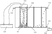
Shown in ginseng Fig. 1 and Fig. 2, Waste Water Treatment 10 comprises reaction cell body 11, electrolyzer 12, electrolysis airing system 13, catalytic material 14 and separate mesh 15.
Electrolyzer 12 comprises positive plate 121, negative plate 122 and power supply 123.Positive plate 121 and negative plate 122 are installed in reaction cell body 11, and are graphite electrode plate.A plurality of graphite electrode plates on the reaction interior edge of cell body 11 from left to right the direction of (water inlet 111 is to the direction of water outlet 112) with certain being intervally arranged, and be electrically connected according to the positive and negative electrode output terminal of the power supply of positive and negative electrode interactive approach and configuration 123, power supply 123 is preferably direct supply.Positive plate 121 and negative plate 122 are perpendicular to the base plate of reaction cell body 11.In actual applications, due to the restriction of reaction cell body 11 volumes, positive plate 121 and negative plate 122 can only be set to one group, only have a positive plate 121 and a negative plate 122.
Carbon back or silica-based particles that catalytic material 14 is carrying transition metal, can also be doped with titanium dioxide in catalytic material 14.This catalytic material 14 can either be from low concentration wastewater selective enrichment pollutent, there is again high degree of electrical catalytic activation performance.In reaction cell body 11, add catalytic material 14, made the treatment effect of low concentration used water difficult to degradate and processing efficiency be greatly enhanced.
The volume that the loadings of catalytic material 14 accounts for reaction cell body 11 is preferably 30%~60%.
Utilize in the process that 10 pairs of waste water of above-mentioned Waste Water Treatment process, by pump, drive, make waste water be transported to water inlet 111, after under meter metering, enter into reaction cell body 11 and carry out catalytic oxidation processing, average reaction time (being hydraulic detention time) is 20min.Waste water effluent quality after treatment can meet the requirement of standard.Emission standard is carried out (being that COD is lower than 50mg/L) according to current urban wastewater treatment firm emission standard (GB18918-2002) I class (A standard).
User according to actual needs, for different waste water or while meeting different purposes demands, capable of regulating reaction times or adjust electrolytic parameter and catalytic material 14 loadings, can meet the processing requirements of dissimilar trade effluent after parameter optimization.
Below in conjunction with embodiment, the effect of Waste Water Treatment 10 provided by the invention is elaborated.
Embodiment 1
Treatment effect analysis to water outlet after refinery water biochemistry.
Refinery water belongs to used water difficult to degradate, and oil refining process water consumption is large, and water quality complexity and the fluctuation of waste discharge are strong.Utilize the above-mentioned Waste Water Treatment 10 that processing power is 60L/h, the discharge water to an oil refinery effluent after biochemistry has carried out the on-the-spot continuous service test of 30 days.Result shows: when influent quality index COD fluctuation changes between 80.0-360mg/L, and mean value 220mg/L; Ammonia nitrogen concentration is when 40.0mg/L left and right, and the control reaction times is 20min, and after reaction, the COD of system water outlet is lower than 50mg/L, and average removal rate can reach 80.1%; The ammonia nitrogen concentration of water outlet, lower than 4mg/L, reaches more than 90% ammonia nitrogen removal frank; When electrolysis finishes, the average sludge output of system is lower than every liter of waste water 50mg.And effluent quality is good and it is steady to change, this illustrative system is fine to organic shock resistance.
Embodiment 2
The treatment effect analysis of water outlet after dyeing waste water biochemistry.
Printing and dyeing industry water consumption is large, and water quality is complicated, and Pollutant levels fluctuation is large.Utilize the above-mentioned Waste Water Treatment 10 that processing power is 60L/h, the discharge water after many dyeing waste water biochemistry has been carried out to the on-the-spot continuous service test of 3 weeks.The main water-quality guideline of experiment water is: influent quality index COD fluctuation changes between 80-120mg/L, during mean value 100mg/L; Colourity is 40-80, and mean value is 60.During experiment, controlling the reaction times is 20min.Water outlet result shows: this device still can reach 60% to the average removal rate of COD, and water outlet COD is lower than 50mg/L, and the clearance of colourity approaches 100%; When electrolysis finishes, the average sludge output of system is lower than every liter of waste water 60mg.Effluent quality is steady, respond well, can reach the water quality standard requirement of reuse water.
Embodiment 3
The advanced treatment effect analysis of water outlet after sanitary wastewater biochemical treatment.
The generation of sanitary wastewater surpasses the quantity discharged of trade effluent at present, becomes the main wastewater source in China's wastewater treatment industry, and it is also the most important potential water source in reuse water field from now on simultaneously.According to the sanitary sewage emission standard of current China, the discharge water COD after require processing is lower than 50 or the standard of 60mg/L.In Jiangsu Province's Taihu Lake basin, require COD lower than 50, and ammonia nitrogen is lower than 5 or 8mg/L.But this standard is for some old sewage works, during its technological design, COD requires lower than 80 or 120mg/L, and to ammonia nitrogen without standard-required.Therefore this technology is suitable for the technological transformation of Dui Lao sewage work and waste water recycling basin from now on.The above-mentioned Waste Water Treatment 10, Dui Yijialao sewage work test in place of 30 days that to utilize processing power be 60L/h, test water quality is: influent quality index COD fluctuation changes between 60-150mg/L, during mean value 105mg/L; Ammonia nitrogen is 20-60mg/L, and mean value is 40mg/L.During experiment, controlling the reaction times is 20min.Water outlet result shows: this device still can reach 70% to the average removal rate of COD, and the clearance of ammonia nitrogen approaches 100%; When electrolysis finishes, the average sludge output of system is lower than every liter of waste water 30mg.Effluent quality is good and variation is steady, respond well, can reach the water quality standard requirement of reuse water.
The above results explanation, Waste Water Treatment 10 of the present invention can be widely used in different wastewater treatments, and treatment effect is good, and system sludge output is low, and process is clean, and processing cost is low, has very large market outlook.
Total the above, in Waste Water Treatment of the present invention, with carbon back or SiO
2base carrying transition metal doped Ti O
2deng prepared can either be from low concentration wastewater selective enrichment pollutent, there is again the environmental catalysis material of high degree of electrical catalytic activation performance; This material requires to be loaded in reaction cell body according to certain loading level, and combines with the electrolysis tech of waste water; Utilize electrolysis airing system simultaneously, while providing oxygen (DO) to activate to power for the negative plate in reaction cell body, produce active oxygen species, the power of directed circulation is also provided for catalytic material simultaneously.Owing to having added catalytic material in reaction cell body, make the treatment effect of low concentration used water difficult to degradate and processing efficiency be greatly enhanced; Compare with current waste water three-dimensional electrolysis technology, this technology adopts is fluidized-bed but not fixed bed, and catalytic material inactivation and fouling risk reduce greatly, and the catalytic efficiency of catalytic material is greatly improved.Mechanical stability strong to the catalytic activity of DO due to catalytic material and catalytic material is good, in treating processes, pollutent is nearly all completely degraded and catalytic material itself is difficult for efflorescence, so the maximum of this technology and traditional electrolysis or three-dimensional electrolysis technology difference is that its energy consumption is low, comprehensive treating process is with low cost, and treating processes is clean, without or few sludge creation.
And the site test results of multiple factory effluent shows, this technological system to the advanced treatment of the water outlet of domestic sewage processing system, the water outlet of dyeing waste water biochemical system and the water outlet of refinery biochemical treatment system etc. have that volume of equipment efficiency is high, treatment effect good, low or without sludge creation, stable effluent quality, running cost is low, energy consumption is little, level of automation is high, simple to operate, and with the compatible many technological merits such as good of original water treatment system.
Above-mentioned explanation to the disclosed embodiments, makes professional and technical personnel in the field can realize or use the present invention.To the multiple modification of these embodiment, will be apparent for those skilled in the art, General Principle as defined herein can, in the situation that not departing from the spirit or scope of the present invention, realize in other embodiments.Therefore, the present invention will can not be restricted to these embodiment shown in this article, but will meet the widest scope consistent with principle disclosed herein and features of novelty.
Claims (2)
1. a Waste Water Treatment, comprise reaction cell body and electrolyzer, described reaction cell body includes the mouth of a river and water outlet, described water inlet and water outlet are located at respectively the upper end of two sidewalls that described reaction cell body is relative, described electrolyzer comprises positive plate, negative plate and power supply, described positive plate and negative plate are located in described reaction cell body, described power supply is electrically connected at described positive plate and negative plate, it is characterized in that: described Waste Water Treatment also comprises electrolysis airing system, catalytic material and separate mesh, described electrolysis airing system comprises aeration tube and pneumatic pump, described aeration tube is located at the bottom of described reaction cell body, described aeration tube is provided with a plurality of, and the parallel bottom that is distributed in reaction cell body, aeration tube is parallel to described positive plate or negative plate setting, aeration tube is located between adjacent positive plate and negative plate, described catalytic material fills in described reaction cell body, described catalytic material is carbon back or the silica-based particles of carrying transition metal, in described catalytic material doped with titanium dioxide, described separate mesh is located at described water outlet.
2. Waste Water Treatment according to claim 1, is characterized in that: described reaction cell body is processed to form by PP plate or PVC plate.
Priority Applications (1)
| Application Number | Priority Date | Filing Date | Title |
|---|---|---|---|
| CN201210095923.0A CN102616893B (en) | 2012-04-01 | 2012-04-01 | Wastewater treatment system |
Applications Claiming Priority (1)
| Application Number | Priority Date | Filing Date | Title |
|---|---|---|---|
| CN201210095923.0A CN102616893B (en) | 2012-04-01 | 2012-04-01 | Wastewater treatment system |
Publications (2)
| Publication Number | Publication Date |
|---|---|
| CN102616893A CN102616893A (en) | 2012-08-01 |
| CN102616893B true CN102616893B (en) | 2014-02-26 |
Family
ID=46557175
Family Applications (1)
| Application Number | Title | Priority Date | Filing Date |
|---|---|---|---|
| CN201210095923.0A Expired - Fee Related CN102616893B (en) | 2012-04-01 | 2012-04-01 | Wastewater treatment system |
Country Status (1)
| Country | Link |
|---|---|
| CN (1) | CN102616893B (en) |
Families Citing this family (6)
| Publication number | Priority date | Publication date | Assignee | Title |
|---|---|---|---|---|
| CN103723869B (en) * | 2012-12-28 | 2015-09-30 | 肖英 | Water cleaner for shower |
| CN103449574B (en) * | 2013-09-12 | 2015-01-14 | 苏州大学 | Wastewater treatment system |
| CN103435133B (en) * | 2013-09-12 | 2015-07-15 | 苏州大学 | Waste water treatment system |
| CN104591351B (en) * | 2015-02-13 | 2016-05-18 | 中新环科(天津)科技有限公司 | A kind of electrolysis with ion-exchange film slot device of processing chemical production wastewater |
| CN108585129B (en) * | 2018-07-03 | 2023-08-29 | 青岛双瑞海洋环境工程股份有限公司 | Three-dimensional electrode wastewater treatment method and equipment with recovery function |
| CN115093059A (en) * | 2022-06-10 | 2022-09-23 | 大连大学 | Treatment facility of EDCs in photodegradation polluted waste water |
Family Cites Families (7)
| Publication number | Priority date | Publication date | Assignee | Title |
|---|---|---|---|---|
| CN1263686C (en) * | 2004-04-07 | 2006-07-12 | 太原理工大学 | Photoelectrocatalysis and oxidation device for treating organic substance in water |
| CN101434443B (en) * | 2007-11-15 | 2011-07-20 | 中国石油化工股份有限公司 | Method and apparatus for treating oil refining sewerage |
| KR20100052962A (en) * | 2008-11-11 | 2010-05-20 | 유림엔마텍(주) | Treatment method using ultrasonic-electrolysis-precipitator for domestic sewage or wasted water |
| CN101691262A (en) * | 2009-10-21 | 2010-04-07 | 中国海洋石油总公司 | Optic-electronics integrated device for treating organic wastewater through catalytic oxidation |
| CN102139939B (en) * | 2011-04-29 | 2012-09-05 | 东莞市星火环保科技有限公司 | Printing and dyeing waste water treatment system |
| CN102381744B (en) * | 2011-09-28 | 2013-11-27 | 天津市环境保护科学研究院 | Polyphase multipole electrocatalytic industrial wastewater processing system for high efficiency biological toxicity removal |
| CN202508904U (en) * | 2012-04-01 | 2012-10-31 | 苏州大学 | Waste water treatment system |
-
2012
- 2012-04-01 CN CN201210095923.0A patent/CN102616893B/en not_active Expired - Fee Related
Also Published As
| Publication number | Publication date |
|---|---|
| CN102616893A (en) | 2012-08-01 |
Similar Documents
| Publication | Publication Date | Title |
|---|---|---|
| CN102616893B (en) | Wastewater treatment system | |
| CN101591082A (en) | Organic electroplating waste water multicomponent oxide pretreatment process and device | |
| CN102874960A (en) | Device and method for treating high-salinity and degradation-resistant organic industrial waste water by performing photoelectrical synchro coupling and catalytic oxidation on three-dimensional particles | |
| CN103936106A (en) | Electrochemical synchronous nitrogen and phosphorus removal apparatus and municipal sewage treatment method | |
| CN202390287U (en) | Internal iron-carbon UASB-SBR (Upflow Anaerobic Sludge Blanket-Sequencing Batch Reactor) coupling system for treatment of printing and dyeing wastewater | |
| CN103482730B (en) | A kind of Electrocatalytic wastewater treatment system | |
| CN102674505B (en) | Special equipment for treating organic sewage by utilizing electro-Fenton reaction | |
| CN113735227A (en) | Aeration type three-dimensional electro-Fenton fluidized bed | |
| CN112174434B (en) | Reactor and method for treating landfill leachate by combining electric Fenton with denitrification biofilter | |
| CN203625090U (en) | Electrocatalytic wastewater treatment system | |
| CN202508904U (en) | Waste water treatment system | |
| CN211255496U (en) | High-standard advanced treatment system for refractory organic matters in comprehensive wastewater of industrial park | |
| CN112441701A (en) | Efficient treatment, recycling and zero emission method and system for shale gas flowback liquid | |
| CN202508903U (en) | Waste water treatment system | |
| CN203529983U (en) | Wastewater treatment system | |
| CN203699987U (en) | Wastewater treatment system | |
| CN104355505B (en) | The treatment system of one way of life waste water | |
| CN105060624A (en) | Sewage treatment biochemical reaction tank | |
| CN210133989U (en) | Solar electro-catalysis integrated sewage purification device | |
| CN107986519A (en) | A kind of electro-catalysis and photocatalysis sewage processing method | |
| CN210176667U (en) | Novel comprehensive phosphorus removal treatment system | |
| CN209815897U (en) | Mineralized nitrogen and phosphorus removal and sludge reduction and ecological filter tank coupling treatment equipment | |
| CN103449574B (en) | Wastewater treatment system | |
| CN204939189U (en) | A kind of sewage disposal biochemical reaction tank | |
| CN103435133B (en) | Waste water treatment system |
Legal Events
| Date | Code | Title | Description |
|---|---|---|---|
| C06 | Publication | ||
| PB01 | Publication | ||
| C10 | Entry into substantive examination | ||
| SE01 | Entry into force of request for substantive examination | ||
| C14 | Grant of patent or utility model | ||
| GR01 | Patent grant | ||
| CF01 | Termination of patent right due to non-payment of annual fee | ||
| CF01 | Termination of patent right due to non-payment of annual fee |
Granted publication date: 20140226 Termination date: 20210401 |