CN102610978A - Method and device for machining motor carbon brush carrier - Google Patents
Method and device for machining motor carbon brush carrier Download PDFInfo
- Publication number
- CN102610978A CN102610978A CN2012101051919A CN201210105191A CN102610978A CN 102610978 A CN102610978 A CN 102610978A CN 2012101051919 A CN2012101051919 A CN 2012101051919A CN 201210105191 A CN201210105191 A CN 201210105191A CN 102610978 A CN102610978 A CN 102610978A
- Authority
- CN
- China
- Prior art keywords
- terminal
- feeding guide
- stamping die
- material belt
- riveted
- Prior art date
- Legal status (The legal status is an assumption and is not a legal conclusion. Google has not performed a legal analysis and makes no representation as to the accuracy of the status listed.)
- Granted
Links
Images


Abstract
The invention discloses a method and device for machining a motor carbon brush carrier. The method for machining the motor carbon brush carrier comprises the following steps of: automatically feeding by utilizing a first terminal material strip, a second terminal material strip and a third terminal material strip; blanking, stamping and bending the first terminal material strip, the second terminal material strip and the third terminal material strip; riveting the first terminal material strip and the second terminal material strip, and cutting down a second terminal at the same time; riveting the first terminal material strip and the third terminal material strip, and cutting down a third terminal at the same time; finally finishing forming and blanking process to a riveted carbon brush. The method and device for machining the motor carbon brush carrier, disclosed by the invention, have the advantages of high machining efficiency and firm terminal riveting; and in addition, the terminals are bent before being riveted, and two different pre-riveting structures can be machined on the first terminal.
Description
Technical field
The present invention relates to the motor part and make field, particularly a kind of processing method of carbon brush for electric machine frame and process equipment thereof.
Background technology
To shown in Figure 4, a kind of carbon brush for electric machine frame 4 comprises the first terminal 1 and is riveted on second terminal 2 and the 3rd terminal 3 on the first terminal 1 like Fig. 1, and in the prior art, the processing method of this kind carbon brush for electric machine frame 4 roughly may further comprise the steps, with reference to Fig. 1~Fig. 4:
(1) mould that adopts a mould to go out a plurality of products stamps out the first terminal 1 with first strip, the some first preparatory riveted construction 11 and the some second preparatory riveted construction 12 that on the first terminal 1, be stamped out, and this first terminal 1 is also by curved two kinks 13 and 14 that extrude;
(2) mould that adopts a mould to go out a plurality of products stamps out second terminal 2 with second strip; The some the 3rd preparatory riveted construction 21 that on second terminal 2, is stamped out and matches with the first preparatory riveted construction 11, this second terminal 2 are also by the curved two bending ligulate shell fragments 22 that extrude;
(3) mould that adopts a mould to go out a plurality of products stamps out the 3rd terminal 3 with the 3rd strip; The some the 4th preparatory riveted construction 31, the three terminals that match with the second preparatory riveted construction 12 that on the 3rd terminal 3, are stamped out are also bent extrusion one " 7 " font shell fragment 32;
(4) with the mode of special fixture the first terminal 1 and second terminal 2 are riveted together, with the mode of special fixture the first terminal 1 and the 3rd terminal 3 are riveted together again, finally process finished product carbon brush for electric machine frame 4 through manual rivet through manual rivet.
The shortcoming of this kind processing method is: production efficiency is low, and labour intensity is big; Three kinds of terminals go out a plurality of products by a mould respectively and are stamped to form, and are difficult to guarantee the moulding of each product and the stability of angle; Three kinds of terminals all need be bent pressure, and its transformation yield is low; The spot that stays during the hand riveting is prone to the surface of oxygenated products, and defective such as the hand riveting also can cause because the location is inaccurate that riveted joint is bad, off normal, pulling-out force are not enough.
Chinese invention patent 200710030090.9 discloses a kind of production method of DC electric machine carbon brush holder; The mode of the elastic arm automatic press combination of adopting brass strip and the self-feeding of beryllium copper strip, the terminal that will be processed by the brass strip again and being processed by the beryllium copper strip is produced; The production efficiency that affair is established in this production method and production thereof is high; And terminal and elastic arm combine firmly, and quality is also secure.Yet the production method of this DC electric machine carbon brush holder and production equipment thereof can not be produced the carbon brush for electric machine frame with three terminals, and it has following defective:
The production method of one of which, this DC electric machine carbon brush holder special-purpose production equipment only have two feeding guides, can't accomplish the transmission of three terminals;
The carbon brush for electric machine frame that two, has three terminals need carry out twice riveted joint and can be assembled, and the production equipment of this DC electric machine carbon brush holder only has a riveted joint stamping die, can't accomplish twice riveted joint; And the first terminal need stamp out two kinds of different preparatory riveted constructions, and the production method of this carbon brush for electric machine frame and equipment can't be accomplished;
Three, the production method of this DC electric machine carbon brush holder special-purpose production equipment can't accomplish curved before the riveted joint and be pressed into shape; Make terminal when riveted joint; Because terminal structure has long extension, very easily produces the problem that extension is interfered each other and superposeed, therefore; Even increase a cover feeding guide and riveted joint stamping die simply, can not accomplish the processing that this kind has the carbon brush for electric machine frame of three terminals.
Summary of the invention
The technical problem that the present invention will solve is to above-mentioned deficiency of the prior art; A kind of processing method that is used to process the carbon brush for electric machine frame with three terminals is provided; This processing method working (machining) efficiency is high, the terminal riveted is firm; And can bend terminal before the riveted and be pressed into shape, can process two kinds of different preparatory riveted constructions the first terminal; For this reason, the present invention also will provide the special processing equipment in a kind of above-mentioned processing method.
For solving above-mentioned first technical problem, technical scheme of the present invention is: a kind of processing method of carbon brush for electric machine frame may further comprise the steps:
A, the first terminal strip is installed in first feeding guide on the workbench, second terminal material belt is installed in second feeding guide on the workbench, the 3rd terminal material belt is installed in the 3rd feeding guide on the workbench; This first feeding guide and second feeding guide are in a certain angle to intersect, and the intersection is provided with the first riveted joint stamping die; This first feeding guide and the 3rd feeding guide are also in a certain angle to intersect, and the intersection is provided with the second riveted joint stamping die;
B, before the first terminal strip and second terminal material belt move to the first riveted joint stamping die; Utilize the mould in first feeding guide outside that the first terminal strip is carried out stamping-out, punching press and bend being pressed into shape; On the first terminal strip, stamp out the first preparatory riveted construction and the second preparatory riveted construction; Utilize the mould in second feeding guide outside that second terminal material belt is carried out stamping-out, punching press and bend being pressed into shape, on second terminal material belt, stamp out the 3rd preparatory riveted construction that matches with the first preparatory riveted construction;
C, when the first terminal strip and second terminal material belt move to the first riveted joint stamping die place simultaneously; Through the first riveted joint stamping die action; With first preparatory riveted construction of the first terminal strip and the 3rd preparatory riveted construction riveted joint of second terminal material belt, downcut second terminal from second terminal material belt simultaneously;
D, have before the first terminal strip and the 3rd terminal material belt of second terminal move to the second riveted joint stamping die in riveted joint; Utilize the mould of the 3rd feeding guide top that the 3rd terminal material belt is carried out stamping-out and bend being pressed into shape, stamping-out goes out the 4th preparatory riveted construction on the 3rd terminal material belt;
E, when riveted joint has the first terminal strip and the 3rd terminal material belt of second terminal to move to the second riveted joint stamping die place simultaneously; Through the second riveted joint stamping die action; With second preparatory riveted construction of the first terminal strip and the 4th preparatory riveted construction riveted joint of the 3rd terminal material belt, downcut the 3rd terminal from the 3rd terminal material belt simultaneously;
F, the first terminal strip, second terminal material belt and the 3rd terminal material belt continue feeding; The first riveted joint stamping die and the second riveted joint stamping die repeat next punching press action; The carbon brush holder of riveted passes through shaping mould and blanking cutter successively, accomplishes the processing of moulding and blanking.
For solving above-mentioned second technical problem; Technical scheme of the present invention is: a kind of process equipment of carbon brush for electric machine frame; Comprise workbench, this workbench is provided with first feeding guide that is used to install and transmit the first terminal strip, the 3rd feeding guide that is used to install and transmit second feeding guide of second terminal material belt and is used to install and transmit the 3rd terminal material belt; This first feeding guide and second feeding guide are in a certain angle to intersect, and the intersection is provided with the first riveted joint stamping die; This first feeding guide and the 3rd feeding guide are also in a certain angle to intersect, and the intersection is provided with the second riveted joint stamping die; Along the direction of transfer of first feeding guide, first feeding guide outside before the first riveted joint stamping die is provided with blanking die, stamping die and curved pressing mold, and first feeding guide outside after the second riveted joint stamping die is provided with shaping mould and blanking cutter; Along the direction of transfer of second feeding guide, be provided with blanking die, stamping die, curved pressing mold and cutter in second feeding guide outside; Along the direction of transfer of the 3rd feeding guide, be provided with blanking die, stamping die and cutter in the 3rd feeding guide outside.
The invention has the beneficial effects as follows: the present invention adopts first feeding guide that the first terminal strip is carried out friction feeding; Adopt second guide rail that second terminal material belt is carried out friction feeding; Adopt the 3rd guide rail that the 3rd terminal material belt is carried out friction feeding, utilize processing moulds such as riveting stamping die that three kinds of terminal material belts are carried out punching press, riveted, curved molded and blank simultaneously, not only production efficiency is high; And the riveted of three kinds of terminals is firm, and the processing yield is high.The present invention on the one hand, can carry out the punching press of two kinds of preparatory riveted constructions to the first terminal before the first terminal strip and second terminal material belt are riveted punching press; On the other hand; Can utilize the curved pressing mold in first feeding guide outside that the first terminal is carried out bending first time and be pressed into shape; Utilize the curved pressing mold in second feeding guide outside that second terminal is bent and be pressed into shape, make three kinds of terminals when punch riveting, the problem that does not exist terminal extension structure to interfere each other or superpose; Simultaneously, make that also three kinds of mutual angles of feeding guide are easier to regulate.
Description of drawings
Fig. 1 is the structural representation of the first terminal.
Fig. 2 is the structural representation of second terminal.
Fig. 3 is the structural representation of the 3rd terminal.
Fig. 4 is the overall structure sketch map of carbon brush for electric machine frame.
Fig. 5 is the work flow sketch map of processing method of the present invention.
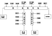
Fig. 6 is the block diagram of process equipment of the present invention.
Embodiment
Below in conjunction with accompanying drawing and embodiment the present invention is done further detailed explanation.
Please with reference to Fig. 5, and combine with reference to Fig. 1~Fig. 4, in this embodiment, a kind of processing method of carbon brush for electric machine frame may further comprise the steps:
A, the first terminal strip 10 is installed in first feeding guide on the workbench 100, second terminal material belt 20 is installed in second feeding guide on the workbench 100, the 3rd terminal material belt 30 is installed in the 3rd feeding guide on the workbench 100; This first feeding guide and second feeding guide are in a certain angle to intersect, and the intersection is provided with the first riveted joint stamping die; This first feeding guide and the 3rd feeding guide are also in a certain angle to intersect, and the intersection is provided with the second riveted joint stamping die;
B, before the first terminal strip 10 and second terminal material belt 20 move to the first riveted joint stamping die; Utilize the mould in first feeding guide outside that the first terminal strip 10 is carried out stamping-out, punching press and bend being pressed into shape; On the first terminal strip, stamp out the first preparatory riveted construction 11 and the second preparatory riveted construction 12; Utilize the mould in second feeding guide outside that second terminal material belt 20 is carried out stamping-out, punching press and bend being pressed into shape, on second terminal material belt 20, stamp out the 3rd preparatory riveted construction 21 that matches with the first preparatory riveted construction 11;
C, when the first terminal strip 10 and second terminal material belt 20 move to the first riveted joint stamping die place simultaneously; Through the first riveted joint stamping die action; With first preparatory riveted construction 11 of the first terminal strip 10 and the 3rd preparatory riveted construction 21 riveted joints of second terminal material belt 20, downcut second terminal 2 from second terminal material belt 20 simultaneously;
D, have before the first terminal strip 10 and the 3rd terminal material belt 30 of second terminal 2 move to the second riveted joint stamping die in riveted joint; Utilize the mould of the 3rd feeding guide top that the 3rd terminal material belt 30 is carried out stamping-out and bend being pressed into shape, stamping-out goes out the 4th preparatory riveted construction 31 on the 3rd terminal material belt 30;
E, when riveted joint has the first terminal strip 10 and the 3rd terminal material belt 30 of second terminal 2 to move to the second riveted joint stamping die place simultaneously; Through the second riveted joint stamping die action; With second preparatory riveted construction 12 of the first terminal strip 10 and the 4th preparatory riveted construction 31 riveted joints of the 3rd terminal material belt 30, downcut the 3rd terminal 3 from the 3rd terminal material belt 30 simultaneously;
F, the first terminal strip 10, second terminal material belt 20 and the 3rd terminal material belt 30 continue feeding; The first riveted joint stamping die and the second riveted joint stamping die repeat next punching press action; The carbon brush holder of riveted passes through shaping mould and blanking cutter successively, accomplishes the moulding and the blanking processing of carbon brush for electric machine frame 4.
In technique scheme, the first terminal 1 has first kink 13 and second kink 14; Before the first terminal strip 10 moved to the first riveted joint stamping die, the first terminal 1 determined of liquidating carried out bending first time and is pressed into shape, makes the first terminal form first kink 13.
In technique scheme, second terminal 2 has two bending shell fragments 22; Before second terminal material belt 20 moved to the first riveted joint stamping die, second terminal 2 determined of liquidating bend and is pressed into shape, made second terminal form the two ligulate shell fragments 22 that bend.
Optimal way as preparatory riveted construction processing; The some down salient points 11 of the said first preparatory riveted construction 11 on the first terminal strip 10, stamping out; The said second preparatory riveted construction 12 for stamp out on the first terminal strip 1 some on salient point 12; The some holes 21 of with said down salient point 11 matching of the said the 3rd preparatory riveted construction 21 on second terminal material belt 20, stamping out, the said the 4th preparatory riveted construction 31 be stamp out on the 3rd terminal material belt 30 with said on salient point 12 some holes 31 of matching.
In technique scheme, said the first terminal strip 10 is the brass strip, and said second terminal material belt 20 and the 3rd terminal material belt 30 are the beryllium copper strip.
Please with reference to Fig. 6; And please combine 1~Fig. 5 with reference to figure; The process equipment of carbon brush for electric machine frame; Comprise workbench 100, this workbench 100 is provided with first feeding guide that is used to install and transmit the first terminal strip 10, the 3rd feeding guide that is used to install and transmit second feeding guide of second terminal material belt 20 and is used to install and transmit the 3rd terminal material belt 30; This first feeding guide and second feeding guide are in a certain angle to intersect, and the intersection is provided with the first riveted joint stamping die; This first feeding guide and the 3rd feeding guide are also in a certain angle to intersect, and the intersection is provided with the second riveted joint stamping die.
Hold; Please refer to Fig. 5 and Fig. 6, along the direction of transfer of first feeding guide, first feeding guide outside before the first riveted joint stamping die is provided with blanking die, stamping die and curved pressing mold; Wherein, Blanking die is used for that stamping-out goes out the first terminal 1 from the first terminal strip 10, and stamping die is used for stamping out the first preparatory riveted construction and the second preparatory riveted construction from the first terminal strip 10, and curved pressing mold is used for extruding first kink 13 from the first terminal; Along the direction of transfer of first feeding guide, first feeding guide outside after the second riveted joint stamping die is provided with shaping mould and blanking cutter, and wherein, shaping mould is used for the moulding of carbon brush for electric machine frame 4, and the blanking cutter is used for carbon brush for electric machine frame 4 is separated with leftover pieces; Direction of transfer along second feeding guide; Be provided with blanking die, stamping die, curved pressing mold and cutter in second feeding guide outside; Wherein, blanking die is used for that stamping-out goes out second terminal 2 from second terminal material belt 20, and stamping die is used for stamping out the 3rd preparatory riveted construction from second terminal material belt 20; Curved pressing mold is used for extruding from second terminal 20 the ligulate shell fragment 22 of two bendings, and cutter is used for second terminal 2 of having riveted is separated with second terminal material belt 20; Direction of transfer along the 3rd feeding guide; Be provided with blanking die, stamping die and cutter in the 3rd feeding guide outside; Blanking die is used for that stamping-out goes out the 3rd terminal 3 from the 3rd terminal material belt 30; Stamping die is used for stamping out the 4th preparatory riveted construction from the 3rd terminal material belt 30, and cutter is used for the 3rd terminal 3 of having riveted is separated with the 3rd terminal material belt 30.
As shown in Figure 6, in technique scheme, the head end of said first feeding guide is provided with first feed arrangement, and tail end is provided with material collecting device; The head end of said second feeding guide is provided with second feed arrangement; The head end of said the 3rd feeding guide is provided with the 3rd feed arrangement.
As a kind of optimal way of the present invention; The stamping die in first feeding guide outside before the first riveted joint stamping die comprises stamping die and following stamping die; Should go up some salient points 11 down that stamping die can stamp out on the first terminal strip 10, this time stamping die can stamp out on the first terminal strip 10 some on salient point 12.
As another kind of optimal way of the present invention, said first feeding guide is positioned at the horizontal of workbench 100, and the left side that said second feeding guide is positioned at workbench 100 is oblique, and said the 3rd feeding guide is oblique in the right side of workbench 100.
The above only is a preferred embodiments of the present invention, and any trickle modification, equivalent variations and modification that every foundation technical scheme of the present invention is done above execution mode all belong in the scope of technical scheme of the present invention.
Claims (9)
1. the processing method of a carbon brush for electric machine frame is characterized in that, may further comprise the steps:
A, the first terminal strip is installed in first feeding guide on the workbench, second terminal material belt is installed in second feeding guide on the workbench, the 3rd terminal material belt is installed in the 3rd feeding guide on the workbench; This first feeding guide and second feeding guide are in a certain angle to intersect, and the intersection is provided with the first riveted joint stamping die; This first feeding guide and the 3rd feeding guide are also in a certain angle to intersect, and the intersection is provided with the second riveted joint stamping die;
B, before the first terminal strip and second terminal material belt move to the first riveted joint stamping die; Utilize the mould in first feeding guide outside that the first terminal strip is carried out stamping-out, punching press and bend being pressed into shape; On the first terminal strip, stamp out the first preparatory riveted construction and the second preparatory riveted construction; Utilize the mould in second feeding guide outside that second terminal material belt is carried out stamping-out, punching press and bend being pressed into shape, on second terminal material belt, stamp out the 3rd preparatory riveted construction that matches with the first preparatory riveted construction;
C, when the first terminal strip and second terminal material belt move to the first riveted joint stamping die place simultaneously; Through the first riveted joint stamping die action; With first preparatory riveted construction of the first terminal strip and the 3rd preparatory riveted construction riveted joint of second terminal material belt, downcut second terminal from second terminal material belt simultaneously;
D, have before the first terminal strip and the 3rd terminal material belt of second terminal move to the second riveted joint stamping die in riveted joint; Utilize the mould of the 3rd feeding guide top that the 3rd terminal material belt is carried out stamping-out and bend being pressed into shape, stamping-out goes out the 4th preparatory riveted construction on the 3rd terminal material belt;
E, when riveted joint has the first terminal strip and the 3rd terminal material belt of second terminal to move to the second riveted joint stamping die place simultaneously; Through the second riveted joint stamping die action; With second preparatory riveted construction of the first terminal strip and the 4th preparatory riveted construction riveted joint of the 3rd terminal material belt, downcut the 3rd terminal from the 3rd terminal material belt simultaneously;
F, the first terminal strip, second terminal material belt and the 3rd terminal material belt continue feeding; The first riveted joint stamping die and the second riveted joint stamping die repeat next punching press action; The carbon brush holder of riveted passes through shaping mould and blanking cutter successively, accomplishes the processing of moulding and blanking.
2. the processing method of carbon brush for electric machine frame according to claim 1 is characterized in that: said the first terminal has first kink and second kink; Before the first terminal strip moved to the first riveted joint stamping die, the first terminal determined of liquidating carried out bending first time and is pressed into shape, makes the first terminal form first kink.
3. the processing method of carbon brush for electric machine frame according to claim 1 is characterized in that: said second terminal has two bending shell fragments; Before second terminal material belt moved to the first riveted joint stamping die, second terminal determined of liquidating bend and is pressed into shape, made second terminal form the two ligulate shell fragments that bend.
4. the processing method of carbon brush for electric machine frame according to claim 1; It is characterized in that: the said first preparatory riveted construction is the some salient points down that on the first terminal strip, stamp out; The said second preparatory riveted construction for stamp out on the first terminal strip some on salient point; The some holes of with said down salient point matching of the said the 3rd preparatory riveted construction on second terminal material belt, stamping out, the said the 4th preparatory riveted construction be stamp out on the 3rd terminal material belt with said on salient point some holes of matching.
5. the processing method of carbon brush for electric machine frame according to claim 1 is characterized in that: said the first terminal strip is the brass strip, and said second terminal material belt and the 3rd terminal material belt are the beryllium copper strip.
6. the process equipment of a carbon brush for electric machine frame; It is characterized in that: comprise workbench, this workbench is provided with first feeding guide that is used to install and transmit the first terminal strip, the 3rd feeding guide that is used to install and transmit second feeding guide of second terminal material belt and is used to install and transmit the 3rd terminal material belt; This first feeding guide and second feeding guide are in a certain angle to intersect, and the intersection is provided with the first riveted joint stamping die; This first feeding guide and the 3rd feeding guide are also in a certain angle to intersect, and the intersection is provided with the second riveted joint stamping die; Along the direction of transfer of first feeding guide, first feeding guide outside before the first riveted joint stamping die is provided with blanking die, stamping die and curved pressing mold, and first feeding guide outside after the second riveted joint stamping die is provided with shaping mould and blanking cutter; Along the direction of transfer of second feeding guide, be provided with blanking die, stamping die, curved pressing mold and cutter in second feeding guide outside; Along the direction of transfer of the 3rd feeding guide, be provided with blanking die, stamping die and cutter in the 3rd feeding guide outside.
7. the process equipment of carbon brush for electric machine frame according to claim 6 is characterized in that: the head end of said first feeding guide is provided with first feed arrangement, and tail end is provided with material collecting device; The head end of said second feeding guide is provided with second feed arrangement; The head end of said the 3rd feeding guide is provided with the 3rd feed arrangement.
8. the process equipment of carbon brush for electric machine frame according to claim 6; It is characterized in that: the stamping die in first feeding guide outside before the first riveted joint stamping die comprises stamping die and following stamping die; Should go up some salient points down that stamping die can stamp out on the first terminal strip, this time stamping die can stamp out on the first terminal strip some on salient point.
9. according to the process equipment of any described carbon brush for electric machine frame of claim in the claim 6~8; It is characterized in that: said first feeding guide is positioned at the horizontal of workbench; The left side that said second feeding guide is positioned at workbench is oblique, and said the 3rd feeding guide is oblique in the right side of workbench.
Priority Applications (1)
| Application Number | Priority Date | Filing Date | Title |
|---|---|---|---|
| CN201210105191.9A CN102610978B (en) | 2012-04-12 | 2012-04-12 | Method and device for machining motor carbon brush carrier |
Applications Claiming Priority (1)
| Application Number | Priority Date | Filing Date | Title |
|---|---|---|---|
| CN201210105191.9A CN102610978B (en) | 2012-04-12 | 2012-04-12 | Method and device for machining motor carbon brush carrier |
Publications (2)
| Publication Number | Publication Date |
|---|---|
| CN102610978A true CN102610978A (en) | 2012-07-25 |
| CN102610978B CN102610978B (en) | 2014-02-05 |
Family
ID=46528205
Family Applications (1)
| Application Number | Title | Priority Date | Filing Date |
|---|---|---|---|
| CN201210105191.9A Active CN102610978B (en) | 2012-04-12 | 2012-04-12 | Method and device for machining motor carbon brush carrier |
Country Status (1)
| Country | Link |
|---|---|
| CN (1) | CN102610978B (en) |
Cited By (9)
| Publication number | Priority date | Publication date | Assignee | Title |
|---|---|---|---|---|
| CN104485562A (en) * | 2014-12-22 | 2015-04-01 | 东莞市富基自动化设备有限公司 | Novel brush holder production line |
| CN105363939A (en) * | 2014-08-11 | 2016-03-02 | 固笙企业有限公司 | A method for combining heat dissipation aluminum boxes and heat dissipation fins and insert pins |
| CN105537433A (en) * | 2016-03-03 | 2016-05-04 | 厦门鑫河机电科技有限公司 | Automatic production equipment for switch elastic sheets |
| CN105720447A (en) * | 2016-03-22 | 2016-06-29 | 安徽孟凌精密电子有限公司 | Manufacturing method of motor carbon brush |
| CN106311902A (en) * | 2016-10-21 | 2017-01-11 | 福州晟鑫机械有限公司 | Riveting molding mould and technique for carbon brush workpiece of carbon brush holder of grinding machine |
| CN108296655A (en) * | 2017-12-25 | 2018-07-20 | 大族激光科技产业集团股份有限公司 | Assemble localization tool, laser-beam welding machine and its working method |
| CN111545645A (en) * | 2020-06-08 | 2020-08-18 | 深圳市亿和精密科技集团有限公司 | Punching die for punching, riveting and one-step forming |
| CN112671178A (en) * | 2021-01-12 | 2021-04-16 | 捷和电机制品(深圳)有限公司 | Carbon brush assembly, direct current motor and manufacturing method of carbon brush assembly |
| CN116995512A (en) * | 2023-09-28 | 2023-11-03 | 江苏艾锐博精密金属科技有限公司 | Stamping process of in-mold riveting wire clamping terminal |
Citations (4)
| Publication number | Priority date | Publication date | Assignee | Title |
|---|---|---|---|---|
| JPS5328401U (en) * | 1976-08-19 | 1978-03-10 | ||
| CN1237020A (en) * | 1999-06-16 | 1999-12-01 | 江鸿仁 | Method for manufacturing improved conducting copper holder of carbon brush for motor |
| CN101162820A (en) * | 2007-08-31 | 2008-04-16 | 东莞市林远实业有限公司 | Manufacturing method of DC electric machine carbon brush holder |
| CN202662955U (en) * | 2012-04-12 | 2013-01-09 | 东莞市林远实业有限公司 | Motor carbon brush holder processing apparatus |
-
2012
- 2012-04-12 CN CN201210105191.9A patent/CN102610978B/en active Active
Patent Citations (4)
| Publication number | Priority date | Publication date | Assignee | Title |
|---|---|---|---|---|
| JPS5328401U (en) * | 1976-08-19 | 1978-03-10 | ||
| CN1237020A (en) * | 1999-06-16 | 1999-12-01 | 江鸿仁 | Method for manufacturing improved conducting copper holder of carbon brush for motor |
| CN101162820A (en) * | 2007-08-31 | 2008-04-16 | 东莞市林远实业有限公司 | Manufacturing method of DC electric machine carbon brush holder |
| CN202662955U (en) * | 2012-04-12 | 2013-01-09 | 东莞市林远实业有限公司 | Motor carbon brush holder processing apparatus |
Cited By (11)
| Publication number | Priority date | Publication date | Assignee | Title |
|---|---|---|---|---|
| CN105363939A (en) * | 2014-08-11 | 2016-03-02 | 固笙企业有限公司 | A method for combining heat dissipation aluminum boxes and heat dissipation fins and insert pins |
| CN104485562A (en) * | 2014-12-22 | 2015-04-01 | 东莞市富基自动化设备有限公司 | Novel brush holder production line |
| CN105537433A (en) * | 2016-03-03 | 2016-05-04 | 厦门鑫河机电科技有限公司 | Automatic production equipment for switch elastic sheets |
| CN105720447A (en) * | 2016-03-22 | 2016-06-29 | 安徽孟凌精密电子有限公司 | Manufacturing method of motor carbon brush |
| CN106311902A (en) * | 2016-10-21 | 2017-01-11 | 福州晟鑫机械有限公司 | Riveting molding mould and technique for carbon brush workpiece of carbon brush holder of grinding machine |
| CN106311902B (en) * | 2016-10-21 | 2018-06-08 | 福州晟鑫机械有限公司 | The riveted molding die and riveted moulding process of sander carbon brush holder carbon brush workpiece |
| CN108296655A (en) * | 2017-12-25 | 2018-07-20 | 大族激光科技产业集团股份有限公司 | Assemble localization tool, laser-beam welding machine and its working method |
| CN111545645A (en) * | 2020-06-08 | 2020-08-18 | 深圳市亿和精密科技集团有限公司 | Punching die for punching, riveting and one-step forming |
| CN112671178A (en) * | 2021-01-12 | 2021-04-16 | 捷和电机制品(深圳)有限公司 | Carbon brush assembly, direct current motor and manufacturing method of carbon brush assembly |
| CN116995512A (en) * | 2023-09-28 | 2023-11-03 | 江苏艾锐博精密金属科技有限公司 | Stamping process of in-mold riveting wire clamping terminal |
| CN116995512B (en) * | 2023-09-28 | 2023-12-26 | 江苏艾锐博精密金属科技有限公司 | Stamping process of in-mold riveting wire clamping terminal |
Also Published As
| Publication number | Publication date |
|---|---|
| CN102610978B (en) | 2014-02-05 |
Similar Documents
| Publication | Publication Date | Title |
|---|---|---|
| CN102610978B (en) | Method and device for machining motor carbon brush carrier | |
| CN203426280U (en) | Continuous stamping die for manufacturing connector terminal | |
| CN204075003U (en) | A kind of shaping dies of flameproof enclosure | |
| CN104998969A (en) | Continuous die for manufacturing vehicle connecting plate and continuous manufacture method of vehicle connecting plate | |
| CN102974686B (en) | Iron pressure plate progressive die | |
| CN104384352A (en) | Continuous stamping die for manufacturing antenna terminal of wearable equipment | |
| CN104438833B (en) | A kind of continuous stamping die manufacturing threading device talk bonder terminal | |
| CN204018535U (en) | A kind of concave bottom bowl progressive die | |
| CN206882509U (en) | A kind of diel of piece terminal | |
| CN115475879A (en) | Continuous stamping die of one shot forming contact pin and material area | |
| CN105728559A (en) | One-die two-socket precise forming die | |
| CN101145667A (en) | A processing technology of plug slice of connector and its special device | |
| CN205414148U (en) | Make continuous stamping die of high -speed transmission backplate communication connector terminal | |
| CN105057469A (en) | Sleeve-formation progressive die | |
| CN101162820B (en) | Manufacturing method of DC electric machine carbon brush holder | |
| CN202662955U (en) | Motor carbon brush holder processing apparatus | |
| CN111014451B (en) | Progressive stamping die of radiator support | |
| CN208195289U (en) | A kind of punching edge rolling mold of full-automatic no waste mine high quality | |
| CN213495967U (en) | Stamping die of wiring fixing plate | |
| CN213496069U (en) | Automatic punching riveting die for combined piece | |
| CN205032569U (en) | Make continuous stamping die of backplate communication connector shielding piece | |
| CN208960748U (en) | It is a kind of for producing the progressive die for penetrating piece | |
| CN210648107U (en) | Continuous machining die for clutch transmission piece | |
| CN112366106A (en) | Stamping structure of wiring element | |
| CN202963192U (en) | Machining tool for ground wire plug-board of motor |
Legal Events
| Date | Code | Title | Description |
|---|---|---|---|
| C06 | Publication | ||
| PB01 | Publication | ||
| C10 | Entry into substantive examination | ||
| SE01 | Entry into force of request for substantive examination | ||
| C14 | Grant of patent or utility model | ||
| GR01 | Patent grant | ||
| TR01 | Transfer of patent right | ||
| TR01 | Transfer of patent right |
Effective date of registration: 20230406 Address after: Room 204, Building 4, No. 2 Zhugongling Third Road, Tangxia Town, Dongguan City, Guangdong Province, 523000 Patentee after: Dongguan Linheng Technology Co.,Ltd. Address before: Tangxia Town, Guangdong city of Dongguan province 523000 Qing Lake Industrial Zone Patentee before: DONGGUAN LINYUAN INDUSTRY Co.,Ltd. |