CN102587736A - Fingerprint encryption electronic lock and bolt driving mechanism thereof - Google Patents
Fingerprint encryption electronic lock and bolt driving mechanism thereof Download PDFInfo
- Publication number
- CN102587736A CN102587736A CN201210094960XA CN201210094960A CN102587736A CN 102587736 A CN102587736 A CN 102587736A CN 201210094960X A CN201210094960X A CN 201210094960XA CN 201210094960 A CN201210094960 A CN 201210094960A CN 102587736 A CN102587736 A CN 102587736A
- Authority
- CN
- China
- Prior art keywords
- dead bolt
- driving mechanism
- gear
- clutch
- lever
- Prior art date
- Legal status (The legal status is an assumption and is not a legal conclusion. Google has not performed a legal analysis and makes no representation as to the accuracy of the status listed.)
- Granted
Links
Images


Landscapes
- Lock And Its Accessories (AREA)
Abstract
The invention provides a bolt driving mechanism, which comprises a first gear, a first motor, a second motor, a first clutch, a second clutch and a clutch control mechanism. The two clutches which are both composed of two coaxially arranged clutch gears are respectively used for transmitting the rotation of the two motors to the first gear. The clutch control mechanism enables the two clutches to be engaged and disengaged respectively. The clutch control mechanism includes a lever, a first pin, a second pin and a driving mechanism of the lever. The two pins are respectively arranged at two ends of the lever and capable of being pushed by the lever to move along the axial direction of the two clutch gears so as to enable the two clutches to be engaged or disengaged. Further provided is a fingerprint encryption electronic lock which comprises a fingerprint sensor, a first control device provided with a fingerprint comparison module and the bolt driving mechanism. The first control device is connected with the bolt driving mechanism. The bolt driving mechanism enables reliability of the electronic lock to be effectively enhanced.
Description
Technical field
The present invention relates to electronic lock, the particularly dead bolt driving mechanism of electronic lock, and the encrypting fingerprint electronic lock that adopts this dead bolt driving mechanism.
Background technology
Realize unblanking electronic lock with locking by general use through the motor-driven dead bolt.But in the higher application scenario of some security requirements, for example the cycle of money case requires lockset that higher reliability is arranged, and preferably can verify the identity of unlocking person.Existing electronic lock can not satisfy these requirements.Therefore; The cycle of money case is started from the consideration of safety of goods in the turnover transportation at present; Plastic buckle normally is set on case lid; Plastic strain through plastics is dead with the casing button by force, this mode poor stability and need strong destruction when uncapping or buckle is deformed to uncap, cause the easy damage of case lid buckle not reuse.
Summary of the invention
The purpose of this invention is to provide a kind of dead bolt driving mechanism, this dead bolt driving mechanism can improve the reliability of electronic lock.
Dead bolt driving mechanism of the present invention comprises:
First gear;
The first and second two motors;
The first and second two clutches, the rotation that is respectively applied for said two motors is passed to said first gear, and said two clutches are formed by two clutch gears of coaxial setting; And
Be used to make said two clutches to be in the clutch for clutch control mechanism of released state and bonding state respectively, comprise lever, respectively be arranged at this lever two ends and can be in the promotion lower edge of this lever moving axially of said two clutch gears said two clutch gears are combined or the first and second two latches separating and the driving mechanism of this lever.
Preferably, the driving mechanism of said lever comprises the 3rd motor and expansion link, and an end of said expansion link connects said lever, and the other end of said expansion link connects the 3rd motor through transmission mechanism.
Preferably; Said expansion link comprises the body of rod, be sheathed on the outer movable component of this body of rod and be fixed in second gear of this body of rod one end; Said movable component comprises framework and the interior spring of this framework, on the said body of rod bearing pin is set, and this bearing pin stretches out from the gap of said spring.
Preferably, said dead bolt driving mechanism also comprises the 3rd gear and the train of reduction gears that is used for the rotation of first gear is passed to the 3rd gear.
Preferably; Said the 3rd gear is a bevel gear; Said dead bolt driving mechanism also comprises the 4th bevel gear with said the 3rd gears engaged; There is a cylinder coaxial with the 4th bevel gear at the 4th bevel gear end face middle part, the first and second two push rods of said cylinder perisporium pin joint, terminal corresponding connection first dead bolt of said two push rods and second dead bolt.
The present invention also provides a kind of encrypting fingerprint electronic lock; It comprises fingerprint sensor, contains first control device and above-mentioned any one dead bolt driving mechanism of fingerprint contrast module; Said first control device is connected with said dead bolt driving mechanism; Be used to control first clutch and be in bonding state and make the first motor-driven dead bolt realize unblanking or locking, and be used for when detecting first electrical fault, second clutch being switched to bonding state and realize unblanking or locking by the second motor-driven dead bolt.
Preferably, on the key that said fingerprint sensor is arranged at lock body separates, the motor in said first control device and the said dead bolt driving mechanism is supplied power by said key.
Preferably, said key comprises first housing, is arranged at second control device and power supply in first housing, and is arranged at the locking button on said first housing, the button of unblanking, display unit, first power supply and communication interface and said fingerprint sensor.
Preferably, on first housing of said key a plurality of electric weight indicator lamps are set.
Preferably, said encrypting fingerprint electronic lock also comprises the travel switch that is used to detect the dead bolt stroke.
Dead bolt driving mechanism of the present invention is provided with two cover power sources; And realize the switching of two cover power sources through lever-type clutch for clutch control mechanism and clutch engagement; After a cover power source is out of order, still can realizes unblanking and lock operation, thereby can effectively improve the reliability of electronic lock.
Owing to adopted above-mentioned dead bolt driving mechanism, encrypting fingerprint electronic lock reliability of the present invention is high, and it can verify that safety is good through fingerprint recognition to the identity of unlocking person simultaneously, therefore can be applied to the cycle of money case.
Description of drawings
Fig. 1 is the structural representation of first embodiment of the invention dead bolt driving mechanism.
Fig. 2 is the structural representation of its expansion link under contraction state.
Fig. 3 is the structural representation of its expansion link under extended state.
Fig. 4 is the structural representation of second embodiment of the invention encrypting fingerprint electronic lock.
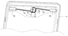
Fig. 5 is the state diagram of second embodiment of the invention encrypting fingerprint electronic lock in the casing outside.
Fig. 6 is the structural representation of the key of second embodiment of the invention encrypting fingerprint electronic lock.
Fig. 7 is the structural representation of third embodiment of the invention encrypting fingerprint electronic lock.
The specific embodiment
Below in conjunction with accompanying drawing and specific embodiment the present invention is further specified.
Fig. 1 shows the dead bolt driving mechanism of first embodiment of the invention.As shown in Figure 1, this dead bolt driving mechanism 1 comprises: the first gear 1d, the first motor 1g, the second motor 1j, first clutch 1f, second clutch 1i and clutch for clutch control mechanism, they are installed among the casing 1a.
First clutch 1f is made up of two the clutch gear 1f1 and the 1f2 that are installed on the 1e; Clutch gear 1f1 and first gear 1d engagement; Gears engaged on another clutch gear 1f2 and the first motor 1g axle is used for the rotation of the first motor 1g is passed to the first gear 1d.
Second clutch 1i is made up of two the clutch gear 1i1 and the 1i2 that are installed on the 1h; Clutch gear 1i1 and first gear 1d engagement; Gears engaged on another clutch gear 1i2 and the second motor 1j axle is used for the rotation of the second motor 1j is passed to the first gear 1d.
Clutch for clutch control mechanism comprises lever 1m, is arranged on the first latch 1l of lever 1m one end, is arranged on second latch 1k of the lever 1m other end and the driving mechanism of lever 1m; Lever 1m rotates counterclockwise and promotes the first latch 1l to the process at terminal and be moved to the left two clutch gear 1f1 and 1f2 combination along axle 1e, rotates counterclockwise in the process lever 1m at this on the other hand and also promotes the second latch 1k and move right along axle 1h two clutch gear 1i1 are separated with 1i2; On the contrary, will promote the first latch 1l to the process at terminal and move right along axle 1e two clutch gear 1f1 are separated with 1f2, and also promote the second latch 1k simultaneously and be moved to the left along axle 1h two clutch gear 1i1 and 1i2 are combined when lever 1m clockwise rotates.That is to say that second clutch 1i was in released state when clutch for clutch control mechanism can make first clutch 1f be in bonding state, and is perhaps opposite.
The driving mechanism of lever 1m comprises the 3rd motor 1p and expansion link 1n; The end of expansion link 1n connects lever 1m; The other end of expansion link 1n connects the 3rd motor 1p through transmission mechanism 1o; Expansion link 1n is shunk the 3rd motor 1p and then activation lever 1m clockwise rotates, and on the contrary, the 3rd motor 1p when reversing expansion link 1n is stretched out and then activation lever 1m rotates counterclockwise.Be appreciated that ground, also have other mode also can promote lever 1m and rotate, for example rotate and drive tooth bar and move, utilize the mobile promotion lever 1m of tooth bar to rotate through the 3rd motor driven gear, etc.
Shown in Fig. 2 and 3; Expansion link 1n comprises body of rod 1n1, be sheathed on the outer movable component 1n2 of body of rod 1n1 and be fixed in the second gear 1n3 of body of rod 1n1 one end; Movable component 1n2 comprises framework 1n4 and the interior spring 1n5 of this framework 1n4; Bearing pin 1n6 is set on the body of rod 1n1, and this bearing pin 1n6 stretches out from the gap of spring 1n5.When the 3rd motor 1p drives the second gear 1n3 and rotates, body of rod 1n1 and on bearing pin 1n6 rotate synchronously, the cooperation through bearing pin 1n6 and spring 1n5 drives movable component 1n2 and body of rod 1n1 relative motion, the contraction of realization expansion link 1n and stretching out.Outside body of rod 1n1 and movable component 1n2, also be provided with a sleeve 1n7.Be appreciated that ground, expansion link also can adopt other structure, for example adopts two pipes nested and through being threaded, and perhaps be placed in the body and be threaded and also can realize with a body of rod, or the like.
In order to save electric energy; The first motor 1g and the second motor 1j adopt the 4.5V direct current generator; In order to guarantee that enough twisting resistances drive dead bolt, this dead bolt driving mechanism 1 also comprises the 3rd gear 1b and the train of reduction gears 1c that is used for the rotation of the first gear 1d is passed to the 3rd gear 1b.
Dead bolt driving mechanism 1 of the present invention is provided with two cover power sources (i.e. first motor and second motor); And realize the switching of two cover power sources through lever-type clutch for clutch control mechanism and clutch engagement; So that after a cover power source is out of order, still can realize unblanking and lock operation.More particularly; When unblanking or during locking, first clutch 1f is in bonding state, second clutch 1i is in released state; The first motor 1g drives the 3rd gear 1b through first clutch 1f, the first gear 1d, train of reduction gears 1c successively and rotates, and drives the dead bolt action through the 3rd gear 1b; When detecting the first motor 1g fault; The 3rd motor 1p rotates through transmission mechanism 1o and expansion link 1n promotion lever 1m and clockwise rotates; Make first clutch 1f switch to released state; Second clutch 1i switches to bonding state, and the second motor 1j drives the 3rd gear 1b through second clutch 1i, the first gear 1d, train of reduction gears 1c successively and rotates, and realizes the driving to dead bolt.
Fig. 4-6 shows the structure of the second embodiment encrypting fingerprint electronic lock.Shown in Fig. 4-6; The second embodiment encrypting fingerprint electronic lock comprises fingerprint sensor 8c, contains the first control device (not shown) of fingerprint contrast module and above-mentioned dead bolt driving mechanism 1; First control device is connected with dead bolt driving mechanism 1; Being used to control first clutch 1f is in bonding state and makes the first motor 1g drive dead bolt 3c to realize unblanking or locking; First control device also is used to detect the first motor 1g, when detecting the first motor 1g fault, starts the 3rd motor 1p and second clutch 1i is switched to bonding state drives dead bolt 3c by the second motor 1j and realize unblanking or locking.
As shown in Figure 4, in a second embodiment, adopt a dead bolt 3c, dead bolt 3c is strip and the latter half of tooth bar that is provided with, the 3rd gear 1b engagement of this tooth bar and dead bolt driving mechanism 1 realizes the driving to dead bolt 3c; Be provided for detecting the travel switch 6 of dead bolt stroke in dead bolt 3c one side, when dead bolt 3c unblanks or after locking put in place, travel switch 6 was given first control device with signal feedback, the stall of control motor.5 for the case lid of cycle of money case among the figure.
Fingerprint sensor 8c is independent mutually with lock body, adopts split-type structural, and promptly fingerprint sensor 8c is arranged on the key 8 that separates with lock body, and the motor 1g in said first control device and the dead bolt driving mechanism 1,1j, 1p are by key 8 power supplies.
Fig. 6 shows a kind of structure of key.As shown in Figure 6; Key 8 comprises the first housing 8a; Be arranged at second control device (not shown) and power supply (not shown) in the first housing 8a, and be arranged at the locking button 8b on the first housing 8a, the button 8e that unblanks, display unit 8f, first power supply and communication interface 8g and fingerprint sensor 8c.Power supply adopts rechargeable battery, in order to understand dump energy easily, is provided with a plurality of electric weight indicator lamp 8d on first housing of key 8.Wherein, display unit 8f adopts LCDs, is used to show state and operation information of lock etc.
When unblanking or during lock operation; With first power supply and the second source on communication interface 8g and the case lid 5 and the grafting of communication interface 7 (see figure 5)s of key 8, gather fingerprint through fingerprint sensor 8c, pass to the interior first control device of lock body after handling through the second control devices in the key 8; Carry out finger print identifying; After authentication was passed through, pressing unblank button 8e or locking button 8b on the key 8 provided to first control device and unblanks or blocking order, and first control device is received 1 work of instruction back control dead bolt driving mechanism; Drive dead bolt 3c action, realize unblanking or locking.
Fig. 7 shows the structure of the 3rd embodiment encrypting fingerprint electronic lock.The difference of the 3rd embodiment and second embodiment only is: second embodiment adopts a dead bolt 3c, adopts gear & rack structure to realize the driving of 1 couple of dead bolt 3c of dead bolt driving mechanism.And the 3rd embodiment adopts double lock tongue, promptly comprises the first dead bolt 3a and the second dead bolt 3b, adopts bevel-gear sett and two push rods to realize the driving to dead bolt; More particularly; In the 3rd embodiment, the 3rd gear 1b of dead bolt driving mechanism 1 is a bevel gear, and dead bolt driving mechanism 1 also comprises the 4th bevel gear 2 with the 3rd gear 1b engagement; There is a cylinder 2a coaxial with the 4th bevel gear 2 at the 4th bevel gear 2 end faces middle parts; The cylinder 2a perisporium pin joint first push rod 2b and the second push rod 2c, the terminal first dead bolt 3a that connects of the first push rod 2b, the terminal second dead bolt 3b that connects of the second push rod 2c.The case lid of 4 expression cycle of money casees among Fig. 7.The remainder of the 3rd embodiment encrypting fingerprint electronic lock is identical with second embodiment, no longer narration.
Be appreciated that ground, in certain embodiments, key and lock body also can adopt the integral type design.
Some embodiments of the present invention encrypting fingerprint electronic lock has the following advantages at least:
1. dead bolt leans on the faint direct current generator of 4.5V to drive, and has effectively reduced the consumption of electric energy, can supply power at the built-in standard-sized poly-lithium battery of key during work;
2. take bi-motor dead bolt driving mechanism, when one of them motor was unblanked with locking because of damage can't drive dead bolt, then another one backup motor started work at once;
3. this electronic lock does not need power supply when operate as normal, just by key power supply is provided when only unblanking with lock operation, can avoid the electronic lock fault that causes because of power failure;
4. be provided with fingerprint identification module, only after recognizing effective finger print information, could open the corresponding function of key.Key disposes small-sized LCDs, makes things convenient for the user to understand the user mode of lock body.The built-in standard size poly-lithium battery of key can the repeated charge operation.
More than through specific embodiment the present invention has been done more detailed explanation; These explanations are not limited to the present invention; Those skilled in the art is according to description of the invention; Can also make and revising or equivalents, all according to variation and the modification done in the claimed range of the present invention, all should belong to the covering scope of Patent right requirement of the present invention.
Claims (10)
1. a dead bolt driving mechanism is characterized in that, comprising:
First gear (1d);
The first and second two motors (1g and 1j);
The first and second two clutches (1f and 1i), the rotation that is respectively applied for said two motors is passed to said first gear, and said two clutches are formed by two clutch gears (1f1 and 1f2) (1i1 and 1i2) of coaxial setting; And
Be used to make said two clutches to be in the clutch for clutch control mechanism of released state and bonding state respectively, comprise lever (1m), respectively be arranged at this lever two ends and can be in the promotion lower edge of this lever moving axially of said two clutch gears said two clutch gears are combined or the first and second two latches (1l and 1k) separating and the driving mechanism of this lever.
2. dead bolt driving mechanism according to claim 1; It is characterized in that: the driving mechanism of said lever comprises the 3rd motor (1p) and expansion link (1n); One end of said expansion link connects said lever, and the other end of said expansion link connects the 3rd motor through transmission mechanism (1o).
3. dead bolt driving mechanism according to claim 2; It is characterized in that: said expansion link comprises the body of rod (1n1), be sheathed on the outer movable component (1n2) of this body of rod and be fixed in second gear (1n3) of this body of rod one end; Said movable component comprises the spring (1n5) in framework (1n4) and this framework; Bearing pin (1n6) is set on the said body of rod, and this bearing pin stretches out from the gap of said spring.
4. dead bolt driving mechanism according to claim 1 is characterized in that: also comprise the 3rd gear (1b) and be used for the rotation of first gear is passed to the train of reduction gears (1c) of the 3rd gear.
5. dead bolt driving mechanism according to claim 4; It is characterized in that: said the 3rd gear is a bevel gear; Said dead bolt driving mechanism also comprises the 4th bevel gear (2) with said the 3rd gear (1b) engagement; There is a cylinder coaxial with the 4th bevel gear (2a) at the 4th bevel gear end face middle part, the first and second two push rods (2b and 2c) of said cylinder perisporium pin joint, terminal corresponding connection first dead bolt (3a) of said two push rods and second dead bolt (3b).
6. encrypting fingerprint electronic lock; It is characterized in that: comprise fingerprint sensor (8c), contain first control device and any described dead bolt driving mechanism of claim 1-5 (1) that fingerprint contrasts module; Said first control device is connected with said dead bolt driving mechanism; Be used to control first clutch and be in bonding state and make the first motor-driven dead bolt realize unblanking or locking, and be used for when detecting first electrical fault, second clutch being switched to bonding state and realize unblanking or locking by the second motor-driven dead bolt.
7. encrypting fingerprint electronic lock according to claim 6 is characterized in that: said fingerprint sensor (8c) is arranged on the key (8) that separates with lock body, and the motor in said first control device and the said dead bolt driving mechanism is supplied power by said key.
8. encrypting fingerprint electronic lock according to claim 7; It is characterized in that: said key comprises first housing (8a); Be arranged at second control device and power supply in first housing, and be arranged at the locking button (8b) on said first housing, the button of unblanking (8e), display unit (8f), first power supply and communication interface (8g) and said fingerprint sensor (8c).
9. encrypting fingerprint electronic lock according to claim 8 is characterized in that: a plurality of electric weight indicator lamps (8d) are set on first housing of said key.
10. encrypting fingerprint electronic lock according to claim 6 is characterized in that: said encrypting fingerprint electronic lock also comprises the travel switch (6) that is used to detect the dead bolt stroke.
Priority Applications (1)
| Application Number | Priority Date | Filing Date | Title |
|---|---|---|---|
| CN201210094960.XA CN102587736B (en) | 2012-03-31 | 2012-03-31 | Fingerprint encryption electronic lock and bolt driving mechanism thereof |
Applications Claiming Priority (1)
| Application Number | Priority Date | Filing Date | Title |
|---|---|---|---|
| CN201210094960.XA CN102587736B (en) | 2012-03-31 | 2012-03-31 | Fingerprint encryption electronic lock and bolt driving mechanism thereof |
Publications (2)
| Publication Number | Publication Date |
|---|---|
| CN102587736A true CN102587736A (en) | 2012-07-18 |
| CN102587736B CN102587736B (en) | 2014-12-17 |
Family
ID=46476915
Family Applications (1)
| Application Number | Title | Priority Date | Filing Date |
|---|---|---|---|
| CN201210094960.XA Active CN102587736B (en) | 2012-03-31 | 2012-03-31 | Fingerprint encryption electronic lock and bolt driving mechanism thereof |
Country Status (1)
| Country | Link |
|---|---|
| CN (1) | CN102587736B (en) |
Cited By (7)
| Publication number | Priority date | Publication date | Assignee | Title |
|---|---|---|---|---|
| CN102785112A (en) * | 2012-08-22 | 2012-11-21 | 浙江腾云制冷科技有限公司 | Pulley propelling mechanism for pipe cutter |
| CN103486324A (en) * | 2013-08-20 | 2014-01-01 | 合肥周固智能设备有限公司 | Electric control clutch type valve lockset for a chemical industry production storage and transportation pipeline |
| CN104131745A (en) * | 2014-07-28 | 2014-11-05 | 深圳宝嘉电子设备有限公司 | Transmission mechanism of electronic lock |
| CN105909145A (en) * | 2016-04-14 | 2016-08-31 | 王立崽 | Di-code security door |
| CN106522660A (en) * | 2016-12-27 | 2017-03-22 | 成都申亚科技有限公司 | Lock tongue driving mechanism, lock tongue device and electric control door lock |
| CN106761004A (en) * | 2017-01-04 | 2017-05-31 | 成都申亚科技有限公司 | A kind of intelligent electric-controlled door lock and its control method |
| CN107503589A (en) * | 2017-09-05 | 2017-12-22 | 烟台久环电子科技有限公司 | Bin intelligent lock control system |
Citations (9)
| Publication number | Priority date | Publication date | Assignee | Title |
|---|---|---|---|---|
| CN1737316A (en) * | 2005-08-21 | 2006-02-22 | 徐文祥 | Lock core |
| CN201100025Y (en) * | 2005-08-09 | 2008-08-13 | 常州市溢畅纺织品有限公司 | Micro- power consumption electronic lockset with key providing energy supply |
| EP2150664A1 (en) * | 2007-05-19 | 2010-02-10 | Huf Hülsbeck & Fürst GmbH & Co. KG | Lock cylinder particularly for functions which can be carried out in a vehicle |
| CN201460496U (en) * | 2009-05-27 | 2010-05-12 | 保定市硕成科技有限公司 | Electric antitheft lock easily matched with electronic decoding circuit |
| CN101963012A (en) * | 2009-04-17 | 2011-02-02 | 徐文祥 | Electronic lock drive device, electronic lock core and electronic lock |
| CN201843411U (en) * | 2010-11-03 | 2011-05-25 | 宁波永发集团有限公司 | Motor drive type latching structure for safety deposit box |
| CN201915725U (en) * | 2010-12-07 | 2011-08-03 | 王茜 | Novel remote control bolt lock |
| CN201981885U (en) * | 2011-03-11 | 2011-09-21 | 浙江金财工贸有限公司 | Emergent anti-theft lock of invisible belt |
| CN202023422U (en) * | 2011-03-31 | 2011-11-02 | 重庆远圣智能锁安全门有限公司 | Intelligent indoor door lock without lockhole |
-
2012
- 2012-03-31 CN CN201210094960.XA patent/CN102587736B/en active Active
Patent Citations (9)
| Publication number | Priority date | Publication date | Assignee | Title |
|---|---|---|---|---|
| CN201100025Y (en) * | 2005-08-09 | 2008-08-13 | 常州市溢畅纺织品有限公司 | Micro- power consumption electronic lockset with key providing energy supply |
| CN1737316A (en) * | 2005-08-21 | 2006-02-22 | 徐文祥 | Lock core |
| EP2150664A1 (en) * | 2007-05-19 | 2010-02-10 | Huf Hülsbeck & Fürst GmbH & Co. KG | Lock cylinder particularly for functions which can be carried out in a vehicle |
| CN101963012A (en) * | 2009-04-17 | 2011-02-02 | 徐文祥 | Electronic lock drive device, electronic lock core and electronic lock |
| CN201460496U (en) * | 2009-05-27 | 2010-05-12 | 保定市硕成科技有限公司 | Electric antitheft lock easily matched with electronic decoding circuit |
| CN201843411U (en) * | 2010-11-03 | 2011-05-25 | 宁波永发集团有限公司 | Motor drive type latching structure for safety deposit box |
| CN201915725U (en) * | 2010-12-07 | 2011-08-03 | 王茜 | Novel remote control bolt lock |
| CN201981885U (en) * | 2011-03-11 | 2011-09-21 | 浙江金财工贸有限公司 | Emergent anti-theft lock of invisible belt |
| CN202023422U (en) * | 2011-03-31 | 2011-11-02 | 重庆远圣智能锁安全门有限公司 | Intelligent indoor door lock without lockhole |
Cited By (10)
| Publication number | Priority date | Publication date | Assignee | Title |
|---|---|---|---|---|
| CN102785112A (en) * | 2012-08-22 | 2012-11-21 | 浙江腾云制冷科技有限公司 | Pulley propelling mechanism for pipe cutter |
| CN103486324A (en) * | 2013-08-20 | 2014-01-01 | 合肥周固智能设备有限公司 | Electric control clutch type valve lockset for a chemical industry production storage and transportation pipeline |
| CN103486324B (en) * | 2013-08-20 | 2016-02-03 | 合肥周固智能设备有限公司 | A kind of electric control clutch type valve lockset for Chemical Manufacture accumulating pipeline |
| CN104131745A (en) * | 2014-07-28 | 2014-11-05 | 深圳宝嘉电子设备有限公司 | Transmission mechanism of electronic lock |
| CN105909145A (en) * | 2016-04-14 | 2016-08-31 | 王立崽 | Di-code security door |
| CN105909145B (en) * | 2016-04-14 | 2017-09-22 | 王立崽 | A kind of dicode antitheft door |
| CN106522660A (en) * | 2016-12-27 | 2017-03-22 | 成都申亚科技有限公司 | Lock tongue driving mechanism, lock tongue device and electric control door lock |
| CN106522660B (en) * | 2016-12-27 | 2017-08-25 | 成都申亚科技有限公司 | A kind of bolt driving mechanism, bolt device and electric control door lock |
| CN106761004A (en) * | 2017-01-04 | 2017-05-31 | 成都申亚科技有限公司 | A kind of intelligent electric-controlled door lock and its control method |
| CN107503589A (en) * | 2017-09-05 | 2017-12-22 | 烟台久环电子科技有限公司 | Bin intelligent lock control system |
Also Published As
| Publication number | Publication date |
|---|---|
| CN102587736B (en) | 2014-12-17 |
Similar Documents
| Publication | Publication Date | Title |
|---|---|---|
| CN102587736A (en) | Fingerprint encryption electronic lock and bolt driving mechanism thereof | |
| CN104481280B (en) | Electronic lock with double-motor structure | |
| CN102877707B (en) | Electric lock one is opening structure and open method | |
| CN105275274B (en) | A kind of wisdom identifies lockset | |
| CN105201293A (en) | Intelligent lock and method | |
| CN106347258A (en) | Apparatus for controlling supply of power of battery | |
| CN110080628A (en) | A kind of full-automatic lock body | |
| CN204571495U (en) | A kind of electronic lock with emergent unlocking structure | |
| CN201411984Y (en) | Energy-saving electronic lock | |
| CN104632035A (en) | Novel fingerprint security door | |
| CN106761004A (en) | A kind of intelligent electric-controlled door lock and its control method | |
| CN204386292U (en) | There is the lockset of integration lock panel structure | |
| CN101660374A (en) | Intelligent identity control lock | |
| CN202578194U (en) | Intelligent electronic mechanical lock core | |
| CN105700038A (en) | Electronic equipment and electronic system | |
| CN103556881A (en) | Ring latch device | |
| CN204126458U (en) | Bus inner swing door intelligence external-open control device | |
| CN103280007A (en) | Bluetooth face identification strongbox | |
| CN103225450B (en) | Intelligent safety lock | |
| CN101736964A (en) | Intelligent lock for cases and bags | |
| CN206438853U (en) | A kind of actuating unit of smart lock and the smart lock containing it | |
| CN205577652U (en) | Using mobile phones bluetooth signal control's emergent unlocking means | |
| CN205349008U (en) | Take independent emergent unlocking means of electric switch | |
| CN205778021U (en) | Cabinet lock construction and electronic intelligence locker | |
| CN203640397U (en) | Lock core clutch structure of electronic lock |
Legal Events
| Date | Code | Title | Description |
|---|---|---|---|
| C06 | Publication | ||
| PB01 | Publication | ||
| C10 | Entry into substantive examination | ||
| SE01 | Entry into force of request for substantive examination | ||
| C14 | Grant of patent or utility model | ||
| GR01 | Patent grant |