CN102547347A - Three-dimensional image display apparatus - Google Patents
Three-dimensional image display apparatus Download PDFInfo
- Publication number
- CN102547347A CN102547347A CN2011104478273A CN201110447827A CN102547347A CN 102547347 A CN102547347 A CN 102547347A CN 2011104478273 A CN2011104478273 A CN 2011104478273A CN 201110447827 A CN201110447827 A CN 201110447827A CN 102547347 A CN102547347 A CN 102547347A
- Authority
- CN
- China
- Prior art keywords
- image
- data
- viewpoint
- pixel
- image display
- Prior art date
- Legal status (The legal status is an assumption and is not a legal conclusion. Google has not performed a legal analysis and makes no representation as to the accuracy of the status listed.)
- Pending
Links
Images


Classifications
-
- H—ELECTRICITY
- H04—ELECTRIC COMMUNICATION TECHNIQUE
- H04N—PICTORIAL COMMUNICATION, e.g. TELEVISION
- H04N13/00—Stereoscopic video systems; Multi-view video systems; Details thereof
- H04N13/30—Image reproducers
- H04N13/349—Multi-view displays for displaying three or more geometrical viewpoints without viewer tracking
- H04N13/351—Multi-view displays for displaying three or more geometrical viewpoints without viewer tracking for displaying simultaneously
-
- G—PHYSICS
- G02—OPTICS
- G02B—OPTICAL ELEMENTS, SYSTEMS OR APPARATUS
- G02B30/00—Optical systems or apparatus for producing three-dimensional [3D] effects, e.g. stereoscopic images
-
- H—ELECTRICITY
- H04—ELECTRIC COMMUNICATION TECHNIQUE
- H04N—PICTORIAL COMMUNICATION, e.g. TELEVISION
- H04N13/00—Stereoscopic video systems; Multi-view video systems; Details thereof
- H04N13/30—Image reproducers
- H04N13/302—Image reproducers for viewing without the aid of special glasses, i.e. using autostereoscopic displays
- H04N13/305—Image reproducers for viewing without the aid of special glasses, i.e. using autostereoscopic displays using lenticular lenses, e.g. arrangements of cylindrical lenses
-
- H—ELECTRICITY
- H04—ELECTRIC COMMUNICATION TECHNIQUE
- H04N—PICTORIAL COMMUNICATION, e.g. TELEVISION
- H04N13/00—Stereoscopic video systems; Multi-view video systems; Details thereof
- H04N13/30—Image reproducers
- H04N13/302—Image reproducers for viewing without the aid of special glasses, i.e. using autostereoscopic displays
- H04N13/31—Image reproducers for viewing without the aid of special glasses, i.e. using autostereoscopic displays using parallax barriers
- H04N13/312—Image reproducers for viewing without the aid of special glasses, i.e. using autostereoscopic displays using parallax barriers the parallax barriers being placed behind the display panel, e.g. between backlight and spatial light modulator [SLM]
-
- H—ELECTRICITY
- H04—ELECTRIC COMMUNICATION TECHNIQUE
- H04N—PICTORIAL COMMUNICATION, e.g. TELEVISION
- H04N13/00—Stereoscopic video systems; Multi-view video systems; Details thereof
- H04N13/30—Image reproducers
- H04N13/302—Image reproducers for viewing without the aid of special glasses, i.e. using autostereoscopic displays
- H04N13/31—Image reproducers for viewing without the aid of special glasses, i.e. using autostereoscopic displays using parallax barriers
- H04N13/315—Image reproducers for viewing without the aid of special glasses, i.e. using autostereoscopic displays using parallax barriers the parallax barriers being time-variant
-
- H—ELECTRICITY
- H04—ELECTRIC COMMUNICATION TECHNIQUE
- H04N—PICTORIAL COMMUNICATION, e.g. TELEVISION
- H04N13/00—Stereoscopic video systems; Multi-view video systems; Details thereof
- H04N13/30—Image reproducers
- H04N13/302—Image reproducers for viewing without the aid of special glasses, i.e. using autostereoscopic displays
- H04N13/317—Image reproducers for viewing without the aid of special glasses, i.e. using autostereoscopic displays using slanted parallax optics
Abstract
Disclosed herein is a three-dimensional image display apparatus in which an image for each of a plurality of view points in each of a plurality of observation areas can be observed. The three-dimensional image display apparatus displays one or two images pertaining to a pair of images put in a reverse-view relation in the vicinity of an edge of the observation areas by making use of data different from image data for the view points. Also, the three-dimensional image display apparatus creates one or two images pertaining to a pair of images put in a reverse-view relation in the vicinity of an edge of the observation areas by displaying pieces of image data having a variety of types on a time-division basis.
Description
Technical field
The present invention relates to 3-D image display device.In detail, the present invention relates to alleviate by the so-called contrary nature that (reverse view) cause and the 3-D image display device of sense of discomfort looked.
Background technology
Known multiple 3-D image display device, wherein each is used to and watches two image viewing persons with image of difference (disparity) to realize binocular vision.There are two kinds of main method to be adopted by 3-D image display device.Wherein a kind of is the glasses methods, promptly utilizes glasses to become left eye to use image with image and right eye the separation of images with difference.Another kind is the bore hole method, and the separation of images that promptly under the situation of not utilizing glasses, will have difference becomes left eye to use image with image and right eye.
Under the situation of the 3-D image display device that adopts the bore hole method,, obtained progress in that a kind of specific 3-D image display device is dropped in the actual effort of using.This specific 3-D image display device is roughly to pass through to make up the 3-D image display device that constitutes to optical fractionation parts and image display part, and wherein this image display part is actually 2-dimensional image display device.In the case, these optical fractionation parts comprise that the disparity barrier (parallaxbarrier) that also is called as the difference barrier perhaps has the lens (lens sheet) of lens arra.
For example, utilize disparity barrier normally to go up in vertical direction (being also referred to as longitudinal direction) with having in fact that the disparity barrier of the opening that extends constitutes by image display part as the 3-D image display device of optical fractionation parts.In the case, image display part normally has in the horizontal direction the image display panel of arranging on (being also referred to as transverse direction) and the vertical direction with a plurality of pixels that form two-dimensional matrix.
The 3-D image display device that utilizes the optical fractionation parts can be such device usually: wherein, the optical fractionation parts are set between image display part and the image viewing person, like Japan Patent in early days openly shown in Fig. 7 of No.Hei 5-122733.As replacement; The 3-D image display device that utilizes the optical fractionation parts also can be such device: wherein; Image display part comprises transmission-type liquid crystal display floater and the illuminace component as image display part, shown in Figure 10 of Japan Patent No.3565391.In the case, the optical fractionation parts are set between image display part and the illuminace component.
In the 3-D image display device that the concept map of Figure 60 A and 60B illustrates respectively, the optical fractionation parts are set between image display part and the illuminace component.Under the situation of the 3-D image display device shown in Figure 60 A, the optical fractionation parts are made up of disparity barrier.Under the situation of the 3-D image display device shown in Figure 60 B, the optical fractionation parts are made up of the lens with projection lens arra (lens pillar).In addition, in the 3-D image display device that the concept map of Figure 61 A and 61B illustrates separately, the optical fractionation parts are set between image display part and the image viewing person.Under the situation of the 3-D image display device shown in Figure 61 A, the optical fractionation parts are made up of disparity barrier.Under the situation of the 3-D image display device shown in Figure 61 B, the optical fractionation parts are made up of lens pillar.
Shown in Figure 60 A, the light crowd of the pixel group that next free symbol L2, L4, L6, L8 and L10 represent arrives viewpoint 1, and the light crowd of the pixel group that next free symbol R1, R3, R5, R7 and R9 represent arrives viewpoint 2.Like this, with the be separated by position of predetermined distance of image display part, the image of the image of viewpoint 1 and viewpoint 2 is alternately observed.This phenomenon also takes place in the 3-D image display device shown in Figure 60 B, 61A and the 61B.
If image viewing person's left eye and right eye lay respectively at viewpoint 1 and viewpoint 2.In the case; If the pixel group of being represented by symbol L2, L4, L6, L8 and L10 is used to show left eye and uses image; And be used to show that by the pixel group that symbol R1, R3, R5, R7 and R9 represent right eye uses image, then the observer will use left eye image and right eye to use image understanding to be 3-D view.That is to say that when the image viewing person is in the image that received viewpoint 1 by left eye and right eye when receiving in the zone of image of viewpoint 2, the observer will use image and right eye to use image to be familiar with to be 3-D view to left eye.
Yet right eye receives the position of the image of viewpoint 1 by the image of left eye reception viewpoint 2 if the image viewing person moves to, and left eye is received by right eye with image on the contrary, and right eye is received by left eye with image on the contrary, is in the so-called contrary state of looking.In this state, the image viewing person is perceived as the front portion of the object of observation rear portion of the object of observation and the rear portion of the object of observation is perceived as its front portion conversely, therefore feels unnatural and uncomfortable.
In Japan Patent alerting bulletin No.2000-47139, described to alleviating by the so-called contrary effort that the nature that causes and sense of discomfort are done of looking.Particularly; Japan Patent alerting bulletin No.2000-47139 discloses a kind of 3-D image display device; Its detected image observer's position, and, change the shape of sheltering pattern with the corresponding optical modulator of optical fractionation parts according to detected image viewing person's position.Japan Patent alerting bulletin No.2000-47139 has also described a kind of 3-D image display device, its detected image observer's position, and, change the content of images displayed on image display part according to detected image viewing person's position.
Summary of the invention
Above-mentioned 3-D image display device has detected image observer's position and controls image display part and optical fractionation configuration of components based on detected position, requires complicated configuration and complicated control, thereby causes expensive.In addition, when a plurality of image viewing persons observe a 3-D image display device from different position, further produced control to the 3-D image display device problem of difficulty more that becomes.
Thereby; A hope of the present invention provides a kind of 3-D image display device; Even a plurality of image viewing persons observe this 3-D image display device from different position, can be not difficultly, under the situation that does not require complex configurations and complicated control, alleviate by so-called against looking not nature and the sense of discomfort that causes yet.
In order to realize above-mentioned hope; According to the first embodiment of the present invention; A kind of 3-D image display device is provided, wherein can have observed the image of each viewpoint in a plurality of viewpoints that are used in each viewing area of a plurality of viewing areas, wherein; The data that this 3-D image display device utilization is different with the view data that is used for these viewpoints show to belong near the edge of viewing area, to be in a contrary image or two images of looking a pair of the image of relation.
In order to realize above-mentioned hope; According to a second embodiment of the present invention; A kind of 3-D image display device is provided, wherein can have observed the image of each viewpoint in a plurality of viewpoints that are used in each viewing area of a plurality of viewing areas, wherein; This 3-D image display device is in a contrary image or two images of looking a pair of the image of relation through showing to have polytype multiple bar chart as data with time division way, produce to belong near the edge of viewing area.
3-D image display device according to the first and second aspects of the present invention can reduce near the contrary degree of looking in edge of viewing area, and need not detected image observer's position and need not to control image display part or the like according to detected position.In addition, though a plurality of image viewing person from different observation 3-D image display devices, 3-D image display device also can alleviate by so-called contrary not nature and the sense of discomfort that causes of looking.
Description of drawings
Fig. 1 is the perspective view of model that the 3-D image display device of virtual separation according to an embodiment of the invention is shown;
Fig. 2 is the diagrammatic sketch that illustrates as the top view of the model model of the relation between the position of opening that is used for explaining 3-D image display device and sub-pixel, that provide for the part of optical fractionation parts and viewing area;
Fig. 3 illustrates the viewpoint A that is used for the viewing area shown in the key diagram 1
1To A
9, image display part, optical fractionation parts and illuminace component the position between the diagrammatic sketch of top view of model of relation;
Fig. 4 illustrates to be used for explaining as from the light of the sub-pixel viewpoint A towards the viewing area of central authorities
1To A
9The diagrammatic sketch of the model of the condition that the condition of propagating will satisfy;
Fig. 5 illustrates to be used for explaining as from the light of the sub-pixel viewpoint A towards the viewing area on right side
1To A
9The diagrammatic sketch of the model of the condition that the condition of propagating will satisfy;
Fig. 6 illustrates to be used for explaining the viewpoint A at the viewing area of central authorities
1To A
9The diagrammatic sketch of the model of the image that the place is observed;
Fig. 7 illustrates to be used for explaining the viewpoint A at the viewing area on right side
1To A
9The diagrammatic sketch of the model of the image that the place is observed;
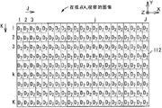
Fig. 8 is the diagrammatic sketch that illustrates as the top view of the model model of the sub-pixel of the pixel that is used for explaining the image that formation each visual field point according to the 3-D image display device of the embodiment of the invention uses, that provide as the part of optical fractionation parts and viewing area;
Fig. 9 be illustrate from (1,1) individual to (M, N) form of the viewpoint that propagates into of the light of subpixels;
Figure 10 is used for explanation to be configured for viewpoint A
4The form of array of one group of sub-pixel of image;
Figure 11 is used for explanation to be configured for viewpoint A
5The form of array of one group of sub-pixel of image;
Figure 12 A illustrates to be used for explanation and to be formed in viewpoint A
4The diagrammatic sketch of the top view of the model of the layout of the pixel of the image of observing;
Figure 12 B illustrates to be used for explanation and to be formed in viewpoint A
5The diagrammatic sketch of the top view of the model of the layout of the pixel of the image of observing;
Figure 13 illustrates to be used for explanation based on being respectively applied for viewpoint A
1To A
9View data D
1To view data D
9Generate the diagrammatic sketch of model of the method for multi-view image video data;
Figure 14 shows and is used to be illustrated as the sub-pixel 12 that is in the capable intersection point place of m row and n
(m, n)The flow chart of the model of the method for selection view data;
Figure 15 show be used for explanation from (1,1) individual to the (M, N) the viewpoint A that propagates into of the light of subpixels
QThe form of the Q value at place;
Figure 16 shows and illustrates that to be used for (1,1) individual to (M, N) form of the j value of subpixels;
Figure 17 shows and illustrates that to be used for (1,1) individual to (M, N) form of the k value of subpixels;
Figure 18 is the diagrammatic sketch that illustrates as the top view that is used to explain when not alleviating contrary effect of looking model on the image display part model of images displayed data, that produce for the part of viewing area 11;
Figure 19 illustrates as being used to explain that left eye and right eye as the image viewing person lay respectively at viewpoint A
4And A
5The time constitute the diagrammatic sketch of top view of model model, that produce for the part of viewing area of the pixel of the image of observing by left eye and the pixel that constitutes the image of observing by right eye;
Figure 20 A is the diagrammatic sketch that the top view of the model that is used to explain the image of being observed by left eye is shown;
Figure 20 B is the diagrammatic sketch that the top view of the model that is used to explain the image of being observed by right eye is shown;
Figure 21 illustrates as being used to explain that left eye and right eye as the image viewing person lay respectively at viewpoint A
9And A
1The time constitute the diagrammatic sketch of top view of model model, that produce for the part of viewing area of the pixel of the image of observing by left eye and the pixel that constitutes the image of observing by right eye;
Figure 22 A is the diagrammatic sketch that the top view of the model that is used to explain the image of being observed by left eye is shown;
Figure 22 B is the diagrammatic sketch that the top view of the model that is used to explain the image of being observed by right eye is shown;
Figure 23 A illustrates to be used for explanation at first embodiment generation data D
S1(j, the diagrammatic sketch of the model of method k);
Figure 23 B illustrates to be used for explaining the diagrammatic sketch for the model of the operation that generates many viewpoints video data and carry out at first embodiment;
Figure 24 A and 24B illustrate to be used to explain that left eye and right eye as the image viewing person lay respectively at viewpoint A
9And A
1The time image observed by left eye and the image observed by right eye the diagrammatic sketch of top view of model;
Figure 25 A illustrates to be used for explanation and to generate data D in a second embodiment
S2(j, the diagrammatic sketch of the model of method k);
Figure 25 B illustrates the diagrammatic sketch that is used to explain in a second embodiment for the model that generates the operation that many viewpoints video data carries out;
Figure 26 A and 26B illustrate to be used to explain that left eye and right eye as the image viewing person lay respectively at viewpoint A
9And A
1The time image observed by left eye and the image observed by right eye the diagrammatic sketch of top view of model;
Figure 27 A illustrates to be used for explanation at the 3rd embodiment generation data D
C1(j, the diagrammatic sketch of the model of method k);
Figure 27 B illustrates to be used for explaining the diagrammatic sketch for the model of the operation that generates many viewpoints video data and carry out at the 3rd embodiment;
Figure 28 A and 28B illustrate to be used to explain that left eye and right eye as the image viewing person lay respectively at viewpoint A
9And A
1The time image observed by left eye and the image observed by right eye the diagrammatic sketch of top view of model;
Figure 29 A illustrates to be used for explanation at the 4th embodiment generation data D
C2(j, the diagrammatic sketch of the model of method k);
Figure 29 B illustrates to be used for explaining the diagrammatic sketch for the model of the operation that generates many viewpoints video data and carry out at the 4th embodiment;
Figure 30 A and 30B illustrate to be used to explain that left eye and right eye as the image viewing person lay respectively at viewpoint A
9And A
1The time image observed by left eye and the image observed by right eye the diagrammatic sketch of top view of model;
Figure 31 A illustrates to be used for explanation at the 5th embodiment generation data D
Av(j, the diagrammatic sketch of the model of method k);
Figure 31 B illustrates to be used for explaining the diagrammatic sketch for the model of the operation that generates many viewpoints video data and carry out at the 5th embodiment;
Figure 32 A and 32B illustrate to be used to explain that left eye and right eye as the image viewing person lay respectively at viewpoint A
9And A
1The time image observed by left eye and the image observed by right eye the diagrammatic sketch of top view of model;
Figure 33 is the diagrammatic sketch that the model that is used for explaining the operation of carrying out at the 6th embodiment is shown;
Figure 34 A and 34B are that the left eye that illustrates as the image viewing person is positioned at viewpoint A
9The time before the diagrammatic sketch of top view of field and the model of the image of back field;
Figure 35 A and 35B are that the right eye that illustrates as the image viewing person is positioned at viewpoint A
1The time before the diagrammatic sketch of top view of field and the model of the image of back field;
Figure 36 illustrates to be used for explanation in order to alleviate by viewpoint A
1And A
2Between and viewpoint A
8And A
9Yet between the contrary relation of looking cause not from the diagrammatic sketch of the model of the operation of carrying out;
Figure 37 is the diagrammatic sketch that the model that is used for explaining the operation of carrying out at the revision of the 6th embodiment is shown;
Figure 38 illustrates the diagrammatic sketch that is used to explain the model of carrying out interleaved typical case;
Figure 39 illustrates to be used for explaining the diagrammatic sketch for the model of the operation that generates many viewpoints video data and carry out at the 7th embodiment;
Figure 40 A and 40B illustrate to be used to explain that left eye and right eye as the image viewing person lay respectively at viewpoint A
9And A
1The time image observed by left eye and the image observed by right eye the diagrammatic sketch of top view of model;
Figure 41 illustrates to be used for explaining the diagrammatic sketch for the model of the operation that generates many viewpoints video data and carry out at the 8th embodiment;
Figure 42 A and 42B illustrate to be used to explain that left eye and right eye as the image viewing person lay respectively at viewpoint A
9And A
1The time image observed by left eye and the image observed by right eye the diagrammatic sketch of top view of model;
Figure 43 A and 43B illustrate to be used to explain that left eye and right eye as the image viewing person lay respectively at viewpoint A
1And A
2The time image observed by left eye and the image observed by right eye the diagrammatic sketch of top view of model;
Figure 44 A and 44B illustrate to be used to explain that left eye and right eye as the image viewing person lay respectively at viewpoint A
8And A
9The time image observed by left eye and the image observed by right eye the diagrammatic sketch of top view of model;
Figure 45 illustrates to be used for explaining the diagrammatic sketch for the model of the operation that generates many viewpoints video data and carry out at the 9th embodiment;
Figure 46 illustrates to be used for explaining the diagrammatic sketch for the model of the operation that generates many viewpoints video data and carry out at the tenth embodiment;
Figure 47 A and 47B illustrate to be used to explain that left eye and right eye as the image viewing person lay respectively at viewpoint A
9And A
1The time image observed by left eye and the image observed by right eye the diagrammatic sketch of top view of model;
Figure 48 illustrates to be used for explaining the diagrammatic sketch for the model of the operation that generates many viewpoints video data and carry out at the 11 embodiment;
Figure 49 A and 49B illustrate to be used to explain that left eye and right eye as the image viewing person lay respectively at viewpoint A
9And A
1The time image observed by left eye and the image observed by right eye the diagrammatic sketch of top view of model;
Figure 50 illustrates to be used for explaining the diagrammatic sketch for the model of the operation that generates many viewpoints video data and carry out at the 12 embodiment;
Figure 51 A and 51B illustrate to be used to explain that left eye and right eye as the image viewing person lay respectively at viewpoint A
9And A
1The time image observed by left eye and the image observed by right eye the diagrammatic sketch of top view of model;
Figure 52 illustrates to be used for explaining the diagrammatic sketch for the model of the operation that generates many viewpoints video data and carry out at the 13 embodiment;
Figure 53 illustrates to be used for explaining the diagrammatic sketch for the model of the operation that generates many viewpoints video data and carry out at the 14 embodiment;
Figure 54 A and 54B illustrate to be used to explain that left eye and right eye as the image viewing person lay respectively at viewpoint A
9And A
1The time image observed by left eye and the image observed by right eye the diagrammatic sketch of top view of model;
Figure 55 is the perspective view that the model of the 3-D image display device of representing virtual separation is shown;
Figure 56 is the perspective view of model of typical revision that the 3-D image display device of the virtual separation of expression is shown;
Figure 57 is the perspective view that the model of the relation between opening and the sub-pixel is shown;
Figure 58 is the perspective view of model of typical revision that the 3-D image display device of the virtual separation of expression is shown;
Figure 59 is the perspective view that the model of the relation between opening and the sub-pixel is shown;
The concept map of Figure 60 A and 60B illustrates 3-D image display device separately, and wherein the optical fractionation parts are set between image display part and the illuminace component; And
The concept map of Figure 61 A and 61B illustrates 3-D image display device separately, and wherein the optical fractionation parts are set between image display part and the image viewing person.
Embodiment
Below through embodiments of the invention being described with reference to accompanying drawing.Yet implementation of the present invention never is limited to these embodiment.In addition, the various numerical value that use in an embodiment also are typical with the material that is used for making the key element that embodiment uses.In the following description, identical key element is indicated and is illustrated once to avoid repeat specification by identical label with the key element with identical function.Notice that following description is divided into the chapters and sections of following arrangement.
1. to 3-D image display device provided by the invention, its driving method and the generally explanation of item
2. to explanation according to the 3-D image display device of embodiment
3. there is not the operation that 3-D image display device is carried out under the contrary situation of looking
4. first embodiment
5. second embodiment
6. the 3rd embodiment
7. the 4th embodiment
8. the 5th embodiment
9. the 6th embodiment
10. the 7th embodiment
11. the 8th embodiment
12. the 9th embodiment
13. the tenth embodiment
14. the 11 embodiment
15. the 12 embodiment
16. the 13 embodiment
17. the 14 embodiment (and other)
[the 1. explanation of pair 3-D image display device provided by the invention, its driving method and general item]
As by 3-D image display device provided by the invention, be widely used a kind ofly can show the image that is used for these visual field points and be used in the 3-D image display device that a plurality of viewing areas observations are used for the image of these visual field points based on the view data that is used for a plurality of visual field points.In this manual, visual field point also is called as viewpoint.
As stated, according to the 3-D image display device of the first embodiment of the present invention through utilizing the data different with the view data that is used for these visual field points, be presented at be near the edge of viewing area in a pair of image of looking relation one or both.Thereby, can reduce the absolute value of the difference size between near the image (these images are in the contrary image of relation of looking a pair of being formed on the edge of viewing area).As a result, can reduce near the contrary degree of looking in edge of viewing area.In the case, different with the view data that is used for visual field point data can be by constituting having the data that polytype multiple bar chart obtains as data combination.
From the angle of the configuration of simplifying 3-D image display device, be desirable to provide such configuration: wherein, having polytype multiple bar chart is the view data that is used for different visual field points as each bar in the data.Yet, have polytype multiple bar chart and not necessarily will be limited to this configuration as each bar in the data.For example, also such configuration can be provided: wherein, multiple bar chart is generated as data separately from each other, and these data that generated are used as and have polytype multiple bar chart as data.In the case, this multiple bar chart as data comprise through rewriting be used for visual field point view data some or the view data that all generates and be the view data of virtual visual field dot generation.
Such configuration can be provided: wherein; Based on coming the images displayed data to be placed in the array having the data that polytype multiple bar chart obtains as data combination, this array is through obtaining to produce band (stripe) state having the composition arranged alternate of polytype multiple bar chart as data; Perhaps such configuration can be provided: wherein, have polytype multiple bar chart and be arranged to as the composition of data and form the gridiron pattern pattern.
The composition of image is to be the composition of image the configuration of unit arranged alternate with the pixel unit of classifying as or with the pixel by arranged alternate with the typical case of the configuration that produces the band state; And be the composition of image the unit arranged alternate with the pixel column crowd or be the configuration of unit arranged alternate with the pixel column crowd; Wherein each pixel column crowd has a plurality of pixel columns adjacent one another are, and each pixel column crowd has a plurality of pixel columns adjacent one another are.In addition; The typical case that is arranged as the configuration that forms checkerboard pattern to the composition of image is to be the composition of image that unit arranges with the configuration that forms checkerboard pattern and is the composition of image the configuration of unit layout with the formation checkerboard pattern with the pixel group with the pixel, and wherein each pixel group has a plurality of pixels.
Perhaps; Such configuration is provided also can for the 3-D image display device according to the first embodiment of the present invention: wherein, the data different with the view data that is used for visual field point are to have the data that polytype multiple bar chart is made even and all obtained as data through giving.In the case, hope that having polytype multiple bar chart is made up of the view data that is used for different visual field points as each bar in the data.Yet, have polytype multiple bar chart and never be limited to this configuration as each bar in the data.For example, as stated, also such configuration can be provided: wherein, multiple bar chart is generated as data separately from each other, and these data that generated are used as and have polytype multiple bar chart as data.In the case, this multiple bar chart as data comprise through rewriting be used for visual field point view data some or the view data that all generates and be the view data of virtual visual field dot generation.Be noted that through making even as data and all obtains data and mean set through the equal data that obtain that many data that are used for same pixel are made even to having polytype multiple bar chart.In addition, " on average " this speech is not limited to arithmetic average (it is average to be also referred to as addition).That is to say that " on average " this speech also can refer to weighted average.Under average weighted situation, can come suitably to select to be used to calculate average weighted weight coefficient based on the design of 3-D image display device.
Perhaps, such configuration is provided can for the 3-D image display device based on the first embodiment of the present invention: wherein, the data different with the view data that is used for visual field point are the data that are used for other visual field point.
As stated, according to a second embodiment of the present invention 3-D image display device is the display image of image that can show each visual field point of each viewing area that is used for a plurality of viewing areas.This 3-D image display device is through showing to have polytype multiple bar chart as data with time-division (time-division) mode, is formed on to be in one in the contrary a pair of image of looking relation or both near the edge of viewing area.In the case, hope that having polytype multiple bar chart is made up of the view data that is used for different visual field points as each bar in the data.Yet, have polytype multiple bar chart and never be limited to this configuration as each bar in the data.For example, as stated, also such configuration can be provided: wherein, multiple bar chart is generated as data separately from each other, and these data that generated are used as and have polytype multiple bar chart as data.In the case, this multiple bar chart as data comprise through rewriting be used for visual field point view data some or the view data that all generates and be the view data of virtual visual field dot generation.
In the 3-D image display device based on the second embodiment of the present invention, the demonstration that in the operation of carrying out with time division way, obtains can be configured to through carrying out so-called lining by line scan or demonstration that so-called interlacing scan obtains.
If this 3-D image display device is provided with the image display part that is used for showing multi-view image and is used to separate the multi-view image that will on image display part, show and allows to observe the optical fractionation parts of the image of each visual field point that is used for each viewing area, then this 3-D image display device can be configured to comprise that the optical fractionation parts that are arranged between image display part and the image viewing person perhaps comprise the optical fractionation parts that are arranged between image display part and the illuminace component.Under the situation of first configuration that comprises the optical fractionation parts that are arranged between image display part and the image viewing person, known display unit can be used as image display part.The typical case of known display unit is display panels, electroluminescence display panel and Plasmia indicating panel.On the other hand, under the situation of second configuration that comprises the optical fractionation parts that are arranged between image display part and the illuminace component, the known transluscent display panel such as the transmission-type liquid crystal display floater can be used as image display part.In addition, image display part can be monochromatic or colored display unit.
The installation site of optical fractionation configuration of components, optical fractionation parts and the other business relevant with the optical fractionation parts are that specification according to 3-D image display device or the like comes suitably to set.If select disparity barrier to be used as the optical fractionation parts, then can use fixing disparity barrier, perhaps, can use the disparity barrier that can dynamically switch as replacement.
Fixedly disparity barrier can adopt the known method utilization to be produced by the base material that known transparent material constitutes, and said known transparent material for example is acrylic resin, PC (Merlon) resin, ABS resin, PMMA (polymethyl methacrylate), PAR (polyacrylate resin), PET (PETG) or glass.The typical case of known method is combination, the multiple print process such as silk screen print method, ink-jet method and metal mask print process, the rubbing method (electric rubbing method and electroless coating method) of photoetching process and etching method and lifts away from (lift-off) method.The disparity barrier that can dynamically switch on the other hand, can constitute as the valve that can electrically switch through the light valve that utilization is provided with liquid crystal material layer usually.For being used to constitute the type of material of the light valve that uses liquid crystal material layer and the not concrete restriction of operator scheme of liquid crystal material layer.In fact, in some cases, the display panels of monochromatic display unit can be used as dynamic parallax barrier.Can come suitably to set size, wire distribution distance of each opening of disparity barrier or the like according to specification of 3-D image display device or the like.
If lens is used as the optical fractionation parts, then there is not concrete regulation for the configuration of design lens and the structure of lens.For example; Can utilize lens through using aforesaid known transparent material to form with the one mode; Perhaps following lens: wherein, through constituting by above-mentioned material to produce lens arra as use photosensitive resin material or the like in the substrate of sheet form base.Come suitably to confirm the optical power of lens arra, the spacing that produces lens arra and other attributes of lens arra according to specification of 3-D image display device or the like.
In the configuration of the 3-D image display device that comprises transluscent display panel and illuminace component, can use known illuminace component.Configuration for illuminace component is not specifically limited.Yet usually, illuminace component can be configured to utilize the known member such as light source, prismatic lens, diffusion sheet and LGP.
In the embodiment that describes after a while, adopt the transmission type colour liquid crystal display floater of active matrix method to be used as image display part, and fixedly disparity barrier is used as the optical fractionation parts.In addition, in an embodiment, the optical fractionation parts are set between image display part and the illuminace component.Yet implementation of the present invention never is limited to these embodiment.
Display panels be configured to comprise front panel usually, have the rear board of second transparency electrode and be arranged on front panel with first transparency electrode and rear board between liquid crystal material.
More specifically, front panel generally includes first substrate, first transparency electrode and light polarizing film.First substrate is the substrate that is made up of glass.First transparency electrode that is also referred to as common electrode is set on the inner surface of first substrate.First electrode is made up of ITO (indium tin oxide) usually.In addition, light polarizing film is set on the outer surface of first substrate.In addition, under the situation of color liquid crystal display panel, front panel has such configuration: wherein, colour filter is set on the inner surface of first substrate, and colour filter is capped the protective layer that constitutes with by acrylic resin or epoxy resin.On this protective layer, produce first transparency electrode.On first transparency electrode, produce alignment film.The arrangement pattern of colour filter can be triangular arrangement pattern, ribbon arrangement pattern, diagonal arrangement pattern or matrix arrangements pattern.
On the other hand, more specifically, rear board generally includes second substrate, switching device, second transparency electrode and light polarizing film.Second substrate is a glass substrate.On the inner surface of second substrate, produce switching device.Second transparency electrode (be also referred to as pixel electrode, for example be made up of ITO (indium tin oxide)) is controlled to get into conducting or not on-state by switching device.Light polarizing film is set on the outer surface of second substrate.Produce alignment film comprising on the whole surface of second transparency electrode.Various members as constituting the transmission-type liquid crystal display floater can use known member.In like manner, the various liquid crystal materials as constituting the transmission-type liquid crystal display floater can use material known.The typical case of switching device is three terminal devices and two-terminal device.The typical case of three terminal devices is TFT (thin-film transistors), and the typical case of two-terminal device is MIM (metal-insulator-metal) device, rheostat spare and diode.
Be noted that in color liquid crystal display panel first and second transparency electrodes are in overlapped region generating, and the zone that comprises liquid crystal cells is corresponding to sub-pixel.In addition, the emitting red light sub-pixel is to be had the colour filter that red light passes through and constitute with making by the relevant range.In like manner, the green emitting sub-pixel is to be had the colour filter that green light passes through and constitute with making by the relevant range.Likewise, the blue-light-emitting sub-pixel is to be had the colour filter that blue light passes through and constitute with making by the relevant range.The arrangement pattern that the arrangement pattern of the arrangement pattern of the arrangement pattern of emitting red light sub-pixel, green emitting sub-pixel and blue-light-emitting sub-pixel coupling is above to be described as the arrangement pattern of colour filter.
In addition, a kind of configuration can also be provided, the sub-pixel that wherein has one or more types is added to has above-mentioned three types sub-pixel.The typical case of extra sub-pixel be send light with white with the sub-pixel that improves brightness, send light with complementary color with the sub-pixel that enlarges the color reproduction scope, send have yellow light with the sub-pixel that enlarges the color reproduction scope and send have yellow and cyan light to enlarge the sub-pixel of color reproduction scope.
As symbol (M
0, N
0) the presentation video display unit is assumed that the pixel counts M of the situation that shows the common plane image
0* N
0The time, pixel counts (M
0, N
0) value particularly be VGA (640,480), S-VGA (800,600), XGA (1024,768), APRC (1152,900), S-XGA (1280,1024), U-XGA (1600,1200), HD-TV (1920,1080) and Q-XGA (2048,1536).In addition, pixel counts (M
0, N
0) other values comprise (1920,1035), (720,480) and (1280,960).Pixel counts (M
0, N
0) each typical naturally image display resolution of these values.Yet, pixel counts (M
0, N
0) value never be limited to the above example that provides.
The driver part that is used for the driven image display unit can be made up of the various circuit such as picture signal processing unit, timing controlled parts, data driver and gate driver.Circuit devcie that each Tong Guo use in these circuit is known or the like constitutes.
The explanation of the 3-D image display device of embodiment [2. pair according to]
Fig. 1 illustrates the basis perspective view of the model of the 3-D image display device of the virtual separation of the embodiments of the invention of description after a while.
As shown in fig. 1,3-D image display device 1 use image display part 10, illuminace component 20 and be arranged on image display part 10 and illuminace component 20 between optical fractionation parts 30.Illuminace component 20 is the parts that are used to shine the back side of image display part 10.Optical fractionation parts 30 are to be used for separating into the multi-view image that will on image display part 10, show being used for each viewing area WA
L, WA
CAnd WA
RIn the parts of observable image of each visual field point.Be noted that viewing area WA
L, WA
CAnd WA
RAlso be collectively referred to as viewing area WA in some cases.
M * N subpixels 12 is disposed in the viewing area 11 of image display part 10 with formation has the matrix that M row and N are listed as.(on the directions X of figure) arranged M subpixels 12 in the horizontal direction, and (on the Y direction of figure) arranged N subpixels 12 in vertical direction.Be in m row (m=1 wherein, 2 ... and M) and n capable (n=1 wherein, 2 ... and N) the sub-pixel 12 at intersection point place be called as (m, n) subpixels 12 or sub-pixel 12
(m, n)In addition, the sub-pixel 12 that lists of m is called as sub-pixel 12 in some cases
m
As previously mentioned, symbol (M
0, N
0) presentation video display unit 10 is assumed that the pixel counts M of the situation that shows the common plane image
0* N
0The exemplary pixels counting is (1920,1080).Under the situation of common plane image; Each pixel on the common plane image is the set that comprises three subpixels of arranging in the horizontal direction; Promptly comprise and send the sub-pixel with red light, the set of sending sub-pixel and sending sub-pixel, make equality M=M with blue light with green light
0* 3 and N=N
0Set up.That is to say, under the situation of the pixel counts of (1920,1080), equality M=5,760 and N=1,080 sets up.
Each opening row is configured to comprise N opening 31 basically.As will describe after a while, opening 31 forms low-angle in arranged direction and the Y direction that opening lists.Therefore, the opening at the edge of optical fractionation parts 30 row comprise the opening 31 of number less than N.
Be noted that after a while among the Fig. 3 to 7 that discusses, the PET film of not shown base material as optical fractionation parts 30, and only show the model of opening 31 and light-blocking member 32.In addition, in order clearly to distinguish shading state and light transmission state, light-blocking member 32 is shown with black.
When the light that is derived from illuminace component 20 and sees through the opening 31 of optical fractionation parts 30 incided image display part 10, some light were reflected back into optical fractionation parts 30 and illumination optical separating component 30 by image display part 10.Thereby the directive property possibility deterioration of difference images is because some light are reflected back into optical fractionation parts 30 and illumination optical separating component 30 by image display part 10.For head it off, antireflection film is set in a side of image display part 10.This side of image display part 10 is the side near optical fractionation parts 30.As replacement, antireflection film is set in a side of optical fractionation parts 30.This side of optical fractionation parts 30 is the side near image display part 10.If the side at optical fractionation parts 30 is provided with antireflection film, then hope only on light-blocking member 32, antireflection film to be set.Configuration for antireflection film does not have concrete regulation, but can use known antireflection film.
Distance, sub-pixel pitch and aperture pitch between optical fractionation parts 30 and the image display part 10 is configured to satisfy the value of the condition of the desirable 3-D view that occurs on the viewing area WA that allows observation in the specification of 3-D image display device 1, to confirm.Sub-pixel pitch is as the spacing on the directions X of the figure of the spacing of sub-pixel 12.In addition, aperture pitch is as the spacing on the directions X of the figure of the spacing of opening 31.Specifically describe these conditions below.
The number of the viewpoint of images displayed is for the viewing area WA shown in Fig. 1 in according to the 3-D image display device of embodiment
L, WA
CAnd WA
RIn each be nine.Viewing area WA
L, WA
CAnd WA
REach in nine viewpoints be respectively viewpoint A
1, A
2... and A
9Yet implementation of the present invention never is limited to this configuration.That is to say that the number of the viewpoint in the number of viewing area and each viewing area can be configured to suitable value according to the design of 3-D image display device.Be noted that in order to make figure simple, in Figure 56 and 58 of Fig. 1, Fig. 3 to 7 and description after a while, viewing area WA be not shown
LAnd WA
RIn some viewpoints.
Fig. 2 is the diagrammatic sketch that illustrates as the top view of the model model of the relation between the position of opening that is used for explaining 3-D image display device and sub-pixel, that provide for the part of optical fractionation parts and viewing area.
As shown in Figure 2, through with the opening 31 that is associated with sub-pixel 12 on n is capable as benchmark, the opening 31 that is associated with sub-pixel 12 on n+1 the is capable distance that on directions X, squints, this distance approximates the spacing of sub-pixel 12.Thereby the direction and the Y direction that list arrange openings 31 at opening form a low-angle.Be noted that in order to make Fig. 2 simple, make the directions X width of the opening 31 shown in Fig. 2 equal the spacing of the sub-pixel 12 shown in the same figure.Yet the directions X width that shows opening 31 equals this relation typical relation only of the spacing of sub-pixel 12.
At Fig. 2 with in after a while with the Fig. 8 that describes, emitting red light sub-pixel, green emitting sub-pixel and blue-light-emitting sub-pixel are represented by reference symbol R, G and B respectively.
Must be in order to make with reference to the explanation easy to understand of figure 2 and 8 readings; In explanation; The sub-pixel 12 that is in the intersection point place of m subpixels row and n subpixels row is assumed that the emitting red light sub-pixel, and the mid point of this sub-pixel 12 is assumed that and is located at the opening 31 of extension to list through p opening on the Z direction
pThe virtual line at center on.
Fig. 3 illustrates the viewpoint A that is used for the viewing area shown in the key diagram 1
1To A
9, image display part, optical fractionation parts and illuminace component the position between the diagrammatic sketch of top view of model of relation.More specifically, Fig. 3 illustrates the viewpoint A that is used for explaining the viewing area on a virtual plane
1To A
9, image display part, optical fractionation parts and illuminace component the position between the diagrammatic sketch of top view of model of relation.This virtual plane comprise above-described dummy line and with the X-Z plane parallel.
In the drawings, symbol ND and RD represent sub-pixel pitch [mm] and aperture pitch [mm] respectively.Distance [mm] between symbols Z 1 expression opening 31 and the image display part 10, and symbols Z 2 presentation video display units 10 and viewing area WA
L, WA
CAnd WA
REach between distance [mm].In addition, symbol DP representes viewing area WA
L, WA
CAnd WA
REach on per two adjacent visual field points between distance [mm].
Symbol PW representes the width of opening 31, and symbol SW representes the width of light-blocking member 32.Thereby equality RD=SW+PW sets up.Describe qualitatively, the value of formula PW/RD=PW/ (SW+PW) is more little, and the directive property of the image of each visual field point is just good more.Yet the value of formula PW/RD=PW/ (SW+PW) is more little, and the brightness of viewed image is just poor more.Thereby, only need set PW/RD for suitable value based on the specification of 3-D image display device.
From opening 31
pAnd see through sub-pixel 12
(m-4, n), 12
(m-3, n)... with 12
(m+4, n)Light propagate into central observation zone WA respectively
CIn viewpoint A
1, A
2... and A
9Discuss from opening 31 below
pLight ray propagation to central observation zone WA
CIn viewpoint A
1, A
2... and A
9Condition.In order make to discuss easy to understand, suppose that the enough little and argumentation of the A/F PW of opening 31 is absorbed in the track through the light at the center of opening 31.
Fig. 4 illustrates to be used for explaining as from the light of the sub-pixel viewpoint A towards the central observation zone
1To A
9The diagrammatic sketch of the model of the condition that the condition of propagating will satisfy.
On the Z direction, to extend to see through opening 31
pThe virtual line at center as benchmark.Symbol X1 representes this benchmark and sub-pixel 12
(m-4, n)The center between distance, and symbol X2 representes this benchmark and central observation zone WA
CIn viewpoint A
1Between distance.In order to make from opening 31
pAnd see through sub-pixel 12
(m-4, n)Light propagate into central observation zone WA
CIn viewpoint A
1, according to homothetic relation, the formula (1) that provides below satisfying.
Z1∶X1=(Z1+Z2)∶X2...(1)
Since more than X1 and X2 in the formula (1) that provides satisfy X1=4 * ND and X2=4 * DP respectively, will draw the following formula (1 ') that provides in the formula (1) so these formulas are updated to:
Z1∶4×ND=(Z1+Z2)∶4×DP ...(1’)
If the formula (1 ') that provides more than satisfying, then on how much clearly, from opening 31
pAnd see through sub-pixel 12
(m-3, n), 12
(m-2, n)... with 12
(m+4, n)Light also propagate into central observation zone WA respectively
CIn viewpoint A
2, A
3... and A
9
Fig. 5 illustrates to be used for explaining as from the light of the sub-pixel viewpoint A towards the viewing area on right side
1To A
9The diagrammatic sketch of the model of the condition that the condition of propagating will satisfy.
From opening 31
P-1And see through sub-pixel 12
(m-4, n), 12
(m-3, n)... with 12
(m+4, n)Light propagate into right side viewing area WA respectively
RIn viewpoint A
1, A
2... and A
9Discuss from opening 31 below
P-1Light ray propagation to right side viewing area WA
RIn viewpoint A
1, A
2... and A
9Condition.
On the Z direction, to extend to see through opening 31
P-1The virtual line at center as benchmark.Symbol X3 representes this benchmark and sub-pixel 12
(m-4, n)The center between distance, and symbol X4 representes this benchmark and right side viewing area WA
RIn viewpoint A
1Between distance.In order to make from opening 31
P-1And see through sub-pixel 12
(m-4, n)Light propagate into viewing area WA
RIn viewpoint A
1, according to homothetic relation, the formula (2) that provides below satisfying.
Z1∶X3=(Z1+Z2)∶X4...(2)
Since more than X3 and X4 in the formula (2) that provides satisfy X3=RD-X1=RD-4 * ND and X4=RD+5 * DP respectively, will draw the following formula (2 ') that provides in the formula (2) so these formulas are updated to:
Z1∶(RD-4×ND)=(Z1+Z2)∶(RD+5×DP)...(2’)
If the formula (2 ') that provides more than satisfying, then on how much clearly, from opening 31
P+1And see through sub-pixel 12
(m-3, n), 12
(m-2, n)... with 12
(m+4, n)Light also propagate into viewing area WA respectively
RIn viewpoint A
2, A
3... and A
9
From opening 31
P+1And see through sub-pixel 12
(m-4, n), 12
(m-3, n)... with 12
(m+4, n)Light propagate into left sides zone WA respectively
LIn viewpoint A
1, A
2... and A
9From opening 31
P+1Light ray propagation is WA to the left sides zone
LIn viewpoint A
1, A
2... and A
9Condition through obtaining with respect to the condition shown in Z axle counter-rotating Fig. 5.Therefore, omission is to the explanation of these conditions.
Be configured to specification predetermined value apart among Z2 and the DP each based on 3-D image display device 1.In addition, sub-pixel pitch ND confirms according to the structure of image display part 10.Express by the formula (3) and (4) that draw from formula (1 ') and (2 ') respectively apart from Z1 and aperture pitch RD.
Z1=Z2×ND/(DP-ND)...(3)
RD=9×DP×ND/(DP-ND)...(4)
If the sub-pixel pitch ND of image display part 10 is 0.175 [mm], be 3,000 [mm] then apart from Z2, distance B P for example is 65.0 [mm], is found to be about 8.10 [mm] apart from Z1, and aperture pitch RD is found to be about 1.58 [mm].
Note; If the configuration of 3-D image display device 1 be configured to make when the image viewing person move the person that approximates the image viewing greatly left eye and the distance between the right eye half the apart from the time image viewing person can observe the image that is used for another visual field point, then the value of distance B P only need be reduced to half.If the value of distance B P is reduced to 32.5 [mm], then be found to be about 16.2 [mm], and aperture pitch RD is found to be about 1.58 [mm] apart from Z1.
In 3-D image display device 1, to be used to make image display part 10 and optical fractionation parts 30 to be separated from each other above-mentioned apart from Z1 for all unshowned separator among all figure.
Be noted that light-emitting area 21 and the not concrete restriction of the distance between the optical fractionation parts 30 for illuminace component 20.Only need become suitable value to get final product with distance setting between the optical fractionation parts 30 light-emitting area 21 of illuminace component 20 according to the specification of 3-D image display device 1.
In above-mentioned Typical Disposition, the value of aperture pitch RD approximately is nine times of value of sub-pixel pitch ND.Thereby, satisfied M ≈ P * 9 that concern of M and P.
Be configured to make above-mentioned condition to be met apart from Z1 and aperture pitch RD.Satisfying under the situation of these conditions, at viewing area WA
L, WA
CAnd WA
REach in viewpoint A
1, A
2... and A
9Each the place, can observe the image that predetermined viewpoint is used.
Fig. 6 illustrates to be used for explaining the viewpoint A at the viewing area of central authorities
1To A
9The diagrammatic sketch of the model of the image that the place is observed.Fig. 7 illustrates to be used for explaining the viewpoint A at the viewing area on right side
1To A
9The diagrammatic sketch of the model of the image that the place is observed.
As before through illustrated with reference to figure 2, through with the opening 31 that is associated with sub-pixel 12 on n is capable as benchmark, the opening 31 that is associated with sub-pixel 12 on n+1 the is capable distance that on directions X, squints, this distance approximates the spacing of sub-pixel 12.Thereby, through will more than " n " in the description that provides replace with " n+1 " and " m " replaced with " m-1 ", the description that more than provides can be used as for n+1 the explanation of the sub-pixel 12 on capable.In addition, through will more than " n " in the description that provides replace with " n-1 " and " m " replaced with " m+1 ", the description that more than provides can be used as for n-1 the explanation of the sub-pixel 12 on capable.
Therefore; If pay close attention to the sub-pixel 12 on the adjacent triplex row; Then from after a while that the Fig. 9 that describes is obviously visible, the sub-pixel that light saw through 12 that propagates into central vision field point is that sub-pixel 12 squints each other and the equal-sized distance of a subpixels 12 is arranged through exercising for each.Each pixel that is configured for the image of each visual field point is to be made up of the one group of sub-pixel 12 that is arranged in triplex row.
Fig. 8 is the diagrammatic sketch that illustrates as the top view of the model model of the sub-pixel of each pixel that is used for explaining the image that formation each visual field point according to the 3-D image display device of the embodiment of the invention uses, that provide as the part of optical fractionation parts and viewing area.
If n is capable is the row of the central authorities of pixel column, then in Fig. 8, around one group of circle, rectangle and the octagon formation pixel of capital R, G and B.The image that is used for each visual field point has horizontal direction pixel counts J and vertical direction pixel counting K.That is to say that the number of pixel that is used for the image of each visual field point is J * K.In the case, concern that J=M/9 and K=N/3 set up, wherein symbol M and N represent horizontal direction sub-pixel counting and vertical direction sub-pixel counting respectively.Thereby, for M=5,760 and N=1,080, the number of the pixel in the image is J * K=640 * 360.Through with reference to figure 9 to 12, the relation between the sub-pixel 12 of pixel that the image that is configured for each visual field point has been described and composing images display unit is described below.
Fig. 9 be illustrate from (1,1) individual to (M, N) form of the viewpoint that propagates into of the light of subpixels.
At first, description starts from being formed in viewpoint A
4The argumentation of the pixel of the image of observing.At viewpoint A
4The image of observing is by the symbol A in each free form shown in Figure 9
4The sub-pixel of mark constitutes.As previously mentioned, each pixel that is configured for the image of each visual field point is to be made up of the one group of sub-pixel 12 that is arranged in triplex row.Be formed in viewpoint A
4Each pixel of the image of observing is by label 412 expressions, and the pixel that is in the capable intersection point place of j row and k by symbol 412 (j, k) expression, j=1 wherein, 2 ... and J and k=1,2 ... and K.
Figure 10 is used for explanation to be configured for viewpoint A
4The form of array of one group of sub-pixel 12 of image.
As shown in Figure 10, if the horizontal direction array of concerned pixel 412, then clearly, each pixel 412 has nine subpixels that are in respectively on nine different lines.The sum of the pixel 412 on each horizontal direction array is J.On the other hand, if the vertical direction array of concerned pixel 412, then clearly, each pixel 412 has three subpixels that are in respectively on three different rows.The sum of the pixel 412 on each vertical direction array is K.Thereby pixel 412 is arranged to and forms the two-dimensional matrix with J * K the every in other words capable J pixel 412 of pixel 412 and K pixel 412 of every row.These pixels 412 have constituted and have been used for viewpoint A
4Image.
Next, as to being formed in viewpoint A
5The argumentation of the pixel of the image of observing provides following description.At viewpoint A
5The image of observing is by the symbol A in each free form shown in Figure 9
5The sub-pixel of mark constitutes.Be formed in viewpoint A
5Each pixel of the image of observing is by label 512 expressions, and (j k) representes by symbol 512 to be in the pixel at the capable intersection point place of j row and k.
Figure 11 is used for explanation to be configured for viewpoint A
5The form of array of one group of sub-pixel of image.
The arrangement of pixel 512 is identical with above pixel 412 with reference to Figure 10 explanation.As shown in Figure 11, each pixel 512 has nine subpixels 12 that are in respectively on nine horizontal direction arrays on the different lines.The sum of the pixel 512 on each horizontal direction array is J.In addition, each pixel 512 has and is in three three subpixels on the vertical direction array on the different rows respectively.The sum of the pixel 512 on each vertical direction array is K.Thereby pixel 512 is arranged to and forms the two-dimensional matrix with J * K the every in other words capable J pixel 512 of pixel 512 and K pixel 512 of every row.This J * K pixel 512 is formed in viewpoint A
5The image of observing.
As stated, at viewpoint A
4The image of observing is configured to comprise J * K the pixel 412 that is arranged as the formation matrix.In like manner, at viewpoint A
5The image of observing is configured to comprise J * K the pixel 512 that is arranged as the formation matrix.Figure 12 A illustrates to be used for explanation and to be formed in viewpoint A
4The diagrammatic sketch of the top view of the model of the layout of the pixel of the image of observing, and Figure 12 B illustrates to be used for explanation and to be formed in viewpoint A
5The diagrammatic sketch of the top view of the model of the layout of the pixel of the image of observing.
Explanation to the pixel that is formed in the image that other visual field point observes is identical with above-mentioned explanation, and the combination of sub-pixel of each pixel that only is configured for other visual field point is different with combinations thereof.Thereby, omit the pixel of the image that is formed in any other visual field point observation and the explanation of arrangement.Be noted that in the following description, be formed in viewpoint A
1Each pixel of the image of observing is called as pixel 112.In like manner, be formed in viewpoint A
2Each pixel of the image of observing is called as pixel 212.Similarly, be formed in viewpoint A
8Each pixel of the image of observing is called as pixel 812.Likewise, be formed in viewpoint A
9Each pixel of the image of observing is called as pixel 912.
Relation between the sub-pixel of pixel that the image that is configured for each visual field point has been described and composing images display unit is more than described.Next, the multi-view image video data that explanation is used on image display part, showing multi-view image is below described.
Figure 13 illustrates to be used for explanation based on being respectively applied for viewpoint A
1To A
9View data D
1To view data D
9Generate the diagrammatic sketch of model of the method for multi-view image video data.
As shown in Figure 13, view data D
1By the view data D that is used for the emitting red light sub-pixel
1_R, be used for the view data D of green emitting sub-pixel
1_GWith the view data D that is used for the blue-light-emitting sub-pixel
1_BSet constitute.Other every view data D
2To D
9Configuration mode and view data D
1Identical.
View data D
1_R, view data D
1_GWith view data D
1_BEach is respectively applied for naturally and is formed in viewpoint A
1J * K bar the data of J * K pixel of the image of observing.Be used to be in the view data D of the pixel at the capable intersection point place of j row and k
1_RIn some cases by symbol D
1_R(j, k) expression.In like manner, be used to be in the view data D of the pixel at the capable intersection point place of j row and k
1_GIn some cases by symbol D
1_G(j, k) expression.Likewise, be used to be in the view data D of the pixel at the capable intersection point place of j row and k
1_BIn some cases by symbol D
1_B(j, k) expression.In addition, this three view data, i.e. view data D of having different each other types
1_R(j, k), view data D
1_G(j is k) with view data D
1_B(j k), is collectively referred to as view data D in some cases
1(j, k).Other every view data D
2To D
9Configuration mode and view data D
1Identical.Every data D that will describe after a while in addition,
S1, D
S2, D
C1, D
C2And D
AvConfiguration mode and view data D
1Identical.
Figure 14 shows and is used to be illustrated as the sub-pixel 12 that is in the capable intersection point place of m row and n
(m, n)The flow chart of the model of the method for selection view data.
As shown in Figure 9, in 3-D image display device 1, propagate into viewpoint A respectively from the light that is in first to the 9th row and the sub-pixel 12 at the first capable intersection point place in the image display part 10 according to embodiment
1To A
9From the 10th row and the repetition of the light of the sub-pixel that lists subsequently 12 and the identical relation of light from first to the 9th sub-pixel 12 that list.In addition, as previously mentioned, the sub-pixel that light saw through 12 that propagates into central vision field point is for the equal-sized distance of the mutual skew of each row with sub-pixel.
Thereby, from the sub-pixel 12 that is in the capable intersection point place of m row and n
(m, n)Light be called as viewpoint A to the viewpoint of its propagation
Q, wherein subscript Q is the integer in the scope 1 to 9.The value of Q is expressed by the following formula that provides (5).In formula (5), symbol mod (dividend, divisor) refers to the remainder of dividend divided by divisor.
Q=mod(m+n-2,9)+1...(5)
Figure 15 show be used to explain according to more than the formula (5) that provides calculate, as from (1,1) individual to the (M, N) the viewpoint A that propagates into of the light of subpixels
QThe form of Q value of Q value.
In addition, if sub-pixel 12
(m, n)Be to constitute to be in to be used for viewpoint A
QThe capable intersection point place of j row and the k of image pixel one of sub-pixel (j=1 wherein, 2 ... with J and k=1,2 ... and K), then the value of j and k is respectively by the following formula that provides (6) and (7) expression.Be noted that in formula (6) and (7) symbol INT (independent variable) is the function that comes to obtain from this independent variable integer through the fractional part of clipping this independent variable.
j=INT([mod(n-1,3)+m-1]/9)+1...(6)
k=INT((n-1)/3)+1...(7)
Figure 16 illustrates the conduct of calculating based on formula (6) to be used for (1,1) individual to (M, N) form of the j value of the j value of subpixels.On the other hand, Figure 17 shows and the conduct of calculating based on formula (7) is shown to be used for (1,1) individual to (M, N) form of the k value of the k value of subpixels.
In addition; If be 0 (m-1) divided by 3 remainder; Then the sub-pixel that lists of m is to send the sub-pixel with red light, if (m-1) be 1 divided by 3 remainder, then the sub-pixel that lists of m is to send the sub-pixel with green light; And if (m-1) be 2 divided by 3 remainder, then the sub-pixel that lists of m is to send the sub-pixel with blue light.
Thereby, if mod (m-1,3)=0 then is in the sub-pixel 12 at the capable intersection point place of m row and n
(m, n)Be used for viewpoint A
QThe red display data be associated, if mod (m-1,3)=1, then sub-pixel 12
(m, n)Be used for viewpoint A
QGreen video data be associated, and if mod (m-1,3)=2, then sub-pixel 12
(m, n)Be used for viewpoint A
QBlue-display data be associated.
If do not alleviate contrary effect of looking, then viewpoint A
1To A
9In statu quo respectively with view data D
1To view data D
9Be associated.On the other hand, embodiment carries out and comprises that the view data that suitably will be used for some visual field points replaces with the processing of the operation of the view data that is used for other visual field points.
In order to make the explanation easy to understand, the explanation of this paragraph does not alleviate against the selection of the data of the situation of the effect of looking.If do not alleviate contrary effect of looking, then be in the sub-pixel 12 at the capable intersection point place of m row and n
(m, n)Under the situation of mod (m-1,3)=0 with view data D
Q_R(j k) is associated.In addition, if mod (m-1,3)=1, then sub-pixel 12
(m, n)With view data D
Q_G(j k) is associated, and if mod (m-1,3)=2, then sub-pixel 12
(m, n)With view data D
Q_B(j k) is associated.
Because based on having the relation that is arranged the set of sub-pixel 12 in an inclined direction for its pixel that is configured for the image of visual field point separately; As shown in Figure 16; For some sub-pixels 12 that are in the capable intersection point place of M-1 row and M separately; The value of j surpasses the value of J, and the value of J is 640 under the situation of this embodiment.Because the view data that is not associated, so preferably through carrying out such as the value of J is associated this sub-pixel 12 as the exception processing the operation of the value (being j=J) of j with view data with this sub pixel 12.The suggestion reader remembers that a bit promptly, a kind of configuration possibly is provided, the data that wherein are used for the image of each visual field point comprise (J+1) * K bar data.In the case, do not need above-described exception to handle.
Through selecting view data based on said process, can generate to be used on image display part, showing the multi-view image video data of multi-view image.
[the 3. explanation of pair operation that 3-D image display device is carried out under the situation that does not alleviate contrary effect of looking]
Figure 18 is the diagrammatic sketch that illustrates as the top view that is used to explain when not alleviating contrary effect of looking model on image display part 10 model of the data of images displayed, that produce for the part of viewing area 11.
Symbol D among Figure 18
1To D
9Expression is used for the type of the view data of driven element pixel 12 separately.In typical case shown in Figure 180, (m, n) subpixels 12 is by symbol D
5Expression emitting red light sub-pixel.This sub-pixel 12 and view data D
5_R(j k) is associated.The deciphering mode of other sub-pixels that is used for other colors is identical.
When image viewing person's left eye all was arranged in identical viewing area with right eye, the image viewing person was 3-D view with image understanding.For example, image viewing person's left eye and right eye lay respectively at the viewing area WA shown in Fig. 1
CIn viewpoint A
4And A
5The place.In the case, the image of being observed by left eye is by being derived from sub-pixel 12 and propagating into viewpoint A
4Light produce, and the image of being observed by right eye is by being derived from sub-pixel 12 and propagating into viewpoint A
5Light produce.
Figure 19 illustrates to be used to explain that left eye and right eye as the image viewing person lay respectively at viewpoint A
4And A
5The time constitute the diagrammatic sketch of the top view of the model pixel of the image of observing by left eye and the pixel that constitutes the image of observing by right eye, that produce for the part of viewing area 11.
Symbol A shown in Figure 19
4And A
5Represent the viewpoint that the light from sub-pixel 12 propagates into separately.Because before through symbol D has been described with reference to Figure 18
4And D
5, therefore omit D
4And D
5Explanation.
The image viewing person utilizes left eye to observe by by view data D
4The image that the sub-pixel that drives produces, and utilize right eye to observe by by view data D
5The image that the sub-pixel that drives produces.
Figure 20 A is the diagrammatic sketch that the top view of the model that is used to explain the image of being observed by left eye is shown.Figure 20 B is the diagrammatic sketch that the top view of the model that is used to explain the image of being observed by right eye is shown.
The image viewing person utilizes left eye to observe by pixel 412 based on view data D
4(1,1) is to view data D
4(J, the image (shown in Figure 20 A) that K) produces, and the image viewing person utilizes right eye to observe by pixel 512 based on view data D
5(1,1) is to view data D
5(J, the image (shown in Figure 20 B) that K) produces.Because by the difference between the image of left eye and right eye observation, the image viewing person is 3-D view with image understanding.
On the other hand, when image viewing person's left eye and right eye are arranged in different viewing areas, the contrary phenomenon of looking takes place.Look in the phenomenon contrary, on the contrary, left eye is observed by right eye with image, and right eye is observed by left eye with image.The image viewing person perceives the image that front and rear wherein exchanges each other.As a result, the image viewing person feels unnatural and uncomfortable.
For example, if image viewing person's left eye is positioned at the left sides zone WA shown in Fig. 1
LIn viewpoint A
9, and image viewing person's right eye is positioned at central observation zone WA
CIn viewpoint A
1, the image of then being observed by left eye is by being derived from sub-pixel 12 and propagating into viewpoint A
9Light produce, and the image of being observed by right eye is by being derived from sub-pixel 12 and propagating into viewpoint A
1Light produce.
Figure 21 illustrates to be used to explain that left eye and right eye as the image viewing person lay respectively at viewpoint A
9And A
1The time constitute the diagrammatic sketch of the top view of the model pixel of the image of observing by left eye and the pixel that constitutes the image of observing by right eye, that produce for the part of viewing area.
Symbol A shown in Figure 21
1And A
9Represent the viewpoint that the light from sub-pixel propagates into separately.Because before through symbol D has been described with reference to Figure 18
1And D
9, therefore omit D
1And D
9Explanation.
The image viewing person utilizes left eye to observe by by view data D
9The image that the sub-pixel that drives produces, and utilize right eye to observe by by view data D
1The image that the sub-pixel that drives produces.
Figure 22 A is the diagrammatic sketch that the top view of the model that is used to explain the image of being observed by left eye is shown.Figure 22 B is the diagrammatic sketch that the top view of the model that is used to explain the image of being observed by right eye is shown.
Shown in Figure 22 A, the image viewing person utilizes left eye to observe by pixel 912 based on view data D
9(1,1) is to view data D
9(J, the image that K) produces, and shown in Figure 22 B, the image viewing person utilizes right eye to observe by pixel 112 based on view data D
1(1,1) is to view data D
1(J, the image that K) produces.Thereby because right eye observed by left eye with image, and left eye observed by right eye with image, so against looking the phenomenon generation, make the image viewing person feel unnatural and uncomfortable.
[4. first embodiment]
First embodiment realizes the 3-D image display device and the method that is used to drive this 3-D image display device according to the first embodiment of the present invention.
In first embodiment, a pair of image is in contrary looking in the relation near the edge of viewing area.For head it off, through utilizing two images that show this centering with the multiple bar chart that provides for visual field point as the different data of data.Is to have the data that polytype multiple bar chart obtains as data through combination with the multiple bar chart that provides for visual field point as the different data of data.More specifically, having polytype multiple bar chart is that the multiple bar chart that provides for different visuals field point is as data as data.Coming in the images displayed based on have the data that polytype multiple bar chart obtains as data through combination, have polytype multiple bar chart as the composition of data by arranged alternate to produce the band state.
Explanation first embodiment is the summary of the operation that generates the multi-view image video data and carry out below.The multiple bar chart that provides for a plurality of different points of view is combined as data so that generate after a while with the data D that describes
S1More specifically, this multiple bar chart is view data D as data
1With view data D
9Viewpoint A
1With replacement view data D
1Data D
S1Be associated.In like manner, viewpoint A
9Also with replacement view data D
9Data D
S1Be associated.Be noted that viewpoint A
2To A
8Respectively with view data D
2To view data D
8Be associated, wherein do not revise these view data.Then, generate the multi-view image video data according to the flow chart shown in Figure 14.
Figure 23 A illustrates to be used for explanation at first embodiment generation data D
S1(j, the diagrammatic sketch of the model of method k).Figure 23 B illustrates to be used for explaining the diagrammatic sketch for the model of the operation that generates the multi-view image video data and carry out at first embodiment.
Obviously visible from the formula shown in Figure 23 A, if the value of j is an odd number, data D then
S1(j k) is configured to view data D
1(j, k), i.e. D
S1(j, k)=D
1(j, k), and on the other hand, if the value of j is an even number, data D then
S1(j k) is configured to view data D
9(j, k), i.e. D
S1(j, k)=D
9(j, k).That is to say data D
S1(j is to be used for viewpoint A through arranged alternate k)
1View data be used for viewpoint A
9The composition of view data the band state generates to produce.
View data D
1To view data D
9Under situation about not being modified, be provided for driver part 100.Then, driver part 100 generates data D based on the operation shown in Figure 23 A
S1, utilize data D
S1Replacement and viewpoint A
1The view data that is associated, and also utilize data D
S1Replacement and viewpoint A
9The view data that is associated.Be noted that by driver part 100 outside parts and generate data D
S1Configuration also be possible.
Figure 24 A and 24B illustrate to be used to explain that left eye and right eye as the image viewing person lay respectively at viewpoint A
9And A
1The time image observed by left eye and the image observed by right eye the diagrammatic sketch of top view of model.
Shown in Figure 24 A and 24B, respectively at viewpoint A
9And A
1In each of two images observing, be respectively applied for viewpoint A
1And A
9The composition of 2 images by arranged alternate to produce the band state.More specifically, extend on the column direction with the iconic element that produces the band state on line direction by arranged alternate.Yet, because respectively at viewpoint A
9And A
1Two images observing are identical images, so between these two images, do not have difference.Like this, can reduce absolute value as the value that is in the difference between two images that a contrary centering of looking two images of relation comprises.
Thereby, when image viewing person's left eye and right eye is in viewpoint A respectively
9And A
1The time, the image viewing person recognizes as being used for viewpoint A
9And A
1Result and the plane picture that obtains of two image mutual superposition.As a result, the image viewing person can not feel to look unnatural and uncomfortable that phenomenon causes by contrary.Even a plurality of image viewing persons observe images displayed on same 3-D image display device from different position, also can alleviate by contrary no problemly and look unnatural and uncomfortable that phenomenon causes.
At viewpoint A
1And A
9In the image of observing each comprises and is used for viewpoint A
1And A
9The composition of image.Thereby, when image viewing person's left eye and right eye is in viewpoint A respectively
1And A
2The time, as being used for viewpoint A
9The image of observing by left eye of iconic element in the iconic element that comprises and as being used for viewpoint A
2The image of observing by right eye of iconic element in the iconic element that comprises be in contrary looking in the relation.Yet the image of being observed by left eye also comprises and is used for viewpoint A
1Iconic element, and this image is viewpoint A with what will be observed by right eye
2The image that provides is in the normal 3-D view relation.Thereby the image viewing person can not feel by above-mentioned contrary unnatural and uncomfortable that phenomenon causes of looking consumingly.In addition, same, when image viewing person's left eye and right eye is in viewpoint A respectively
8And A
9The time, that observed by left eye is viewpoint A
8The image that provides and be viewpoint A as the iconic element that comprises in the image of observing by right eye
1The iconic element that provides is in contrary looking in the relation.Yet the image of being observed by right eye also comprises and is used for viewpoint A
9Iconic element, and this image is viewpoint A with what will be observed by right eye
2The image that provides is in the normal 3-D view relation.Thereby the image viewing person can not feel by above-mentioned contrary unnatural and uncomfortable that phenomenon causes of looking consumingly.
As stated, view data D
1With view data D
9Be combined so that generate data D
S1Yet, wherein view data D also can be provided
2With view data D
8The configuration that is combined, perhaps view data D wherein
3With view data D
7The configuration that is combined.As another replacement, also a kind of configuration can be provided, wherein, typically, combination is through rewriting view data D
1And data that obtain and through rewriting view data D
9And the data that obtain.Only need come suitably to select multiple bar chart to get final product according to the design of 3-D image display device as the combination of data.
In addition, also a kind of configuration can be provided, wherein have dissimilar three or more multiple bar chart be combined as data so that generate data D
S1For example, wherein view data D also can be provided
1, view data D
5With view data D
9Configuration that is combined or view data D wherein
2, view data D
5With view data D
8The configuration that is combined.As replacement, also a kind of configuration can be provided, wherein, typically, combination is through rewriting view data D
1And the data that obtain, through rewriting view data D
5And data that obtain and through rewriting view data D
9And the data that obtain.
[5. second embodiment]
Second embodiment obtains through revising first embodiment.In the situation of first embodiment, viewpoint A
1And A
9In each and identical data D
S1Be associated.On the other hand, under the situation of second embodiment, viewpoint A
1And A
9Be associated with different pieces of information, as follows.
Explanation second embodiment is the summary of the operation that generates the multi-view image video data and carry out below.Except the above data D that in description, explains to first embodiment
S1In addition, the multiple bar chart that provides for a plurality of different points of view is combined as data so that generate after a while with the data D that describes
S2More specifically, this multiple bar chart is view data D as data
1With view data D
9Then, viewpoint A
1With replacement view data D
1Data D
S1Be associated.On the other hand, viewpoint A
9With replacement view data D
9Data D
S2Be associated.Be noted that viewpoint A
2To A
8Respectively with view data D
2To view data D
8Be associated, wherein do not revise these view data.Then, generate the multi-view image video data according to the flow chart shown in Figure 14.
Figure 25 A illustrates to be used for explanation and to generate data D in a second embodiment
S2(j, the diagrammatic sketch of the model of method k), and Figure 25 B illustrates the diagrammatic sketch that is used to explain in a second embodiment for the model that generates the operation that the multi-view image video data carries out.
In to the description of first embodiment, be used to generate data D through having explained with reference to figure 23A
S1(j, method k).Therefore this method needn't be described once more.
Apparent in view visible to Figure 25 A and Figure 23 A is selected as data D
S1(j, many data k) are exchanged so that obtain each other will be selected as data D
S2(j, many data k).That is to say, if the value of j is an odd number, data D then
S2(j k) is configured to view data D
9(j, k), i.e. D
S2(j, k)=D
9(j, k), and on the other hand, if the value of j is an even number, data D then
S2(j k) is configured to view data D
1(j, k), i.e. D
S2(j, k)=D
1(j, k).Like this, data D
S2(j also is to be used for viewpoint A through arranged alternate k)
1View data be used for viewpoint A
9The composition of view data the band state generates to produce.
Figure 26 A and 26B illustrate to be used to explain that left eye and right eye as the image viewing person lay respectively at viewpoint A
9And A
1The time image observed by left eye and the image observed by right eye the diagrammatic sketch of top view of model.
Shown in Figure 26 A and 26B, respectively at viewpoint A
9And A
1In each of two images observing, be respectively applied for viewpoint A
1And A
9The composition of two images by arranged alternate to produce the band state.More specifically, extend on the column direction with the iconic element that produces the band state on line direction by arranged alternate.Respectively at viewpoint A
9And A
1Two images observing have different stripes and arrange phase place.Yet, because these two images almost are perceived as similar identical image, so do not have difference between these two images in fact.Like this, can reduce absolute value as the value that is in the difference between two images that a contrary centering of looking two images of relation comprises.
Thereby, when image viewing person's left eye and right eye is in viewpoint A respectively
9And A
1The time, the image viewing person recognizes as being used for viewpoint A
9And A
1Result and the plane picture that obtains of two image mutual superposition.As a result, the image viewing person can not feel to look unnatural and uncomfortable that phenomenon causes by contrary.
As previous illustrated in description to first embodiment, also a kind of configuration can be provided, wherein, and typically, combined image data D
2With view data D
8So that generate data D
S2As another replacement, also a kind of configuration can be provided, wherein, typically, combination have dissimilar three or more multiple bar chart as data so that generate data D
S2Only need come suitably to select multiple bar chart to get final product according to the design of 3-D image display device as the combination of data.
[6. the 3rd embodiment]
The 3rd embodiment also realizes the 3-D image display device and the method that is used to drive this 3-D image display device according to the first embodiment of the present invention.
Equally, under the situation of the 3rd embodiment, a pair of image also is in contrary looking in the relation near the edge of viewing area.For head it off, show two images that this is right with the multiple bar chart that provides for visual field point as the different data of data through utilizing.Is to have the data that polytype multiple bar chart obtains as data through combination with the multiple bar chart that provides for visual field point as the different data of data.More specifically, having polytype multiple bar chart is that the multiple bar chart that provides for different visuals field point is as data as data.Coming in the images displayed based on have the data that polytype multiple bar chart obtains as data through combination, have polytype multiple bar chart as the composition of data by arranged alternate to form checkerboard pattern.
In the 3rd embodiment, the multiple bar chart that provides for a plurality of different points of view is combined as data so that generate after a while with the data D that describes
C1More specifically, this multiple bar chart is view data D as data
1With view data D
9Then, viewpoint A
1With replacement view data D
1Data D
C1Be associated.In like manner, viewpoint A
9Also with replacement view data D
9Data D
C1Be associated.Be noted that viewpoint A
2To A
8Respectively with view data D
2To view data D
8Be associated, wherein do not revise these view data.Then, generate the multi-view image video data according to the flow chart shown in Figure 14.
Figure 27 A illustrates to be used for explanation at the 3rd embodiment generation data D
C1(j, the diagrammatic sketch of the model of method k), and Figure 27 B illustrates to be used for explaining the diagrammatic sketch for the model of the operation that generates the multi-view image video data and carry out at the 3rd embodiment.
Obviously visible from the formula shown in Figure 27 A, if the value of j+k is an odd number, data D then
C1(j k) is configured to view data D
1(j, k), i.e. D
C1(j, k)=D
1(j, k), and on the other hand, if the value of j+k is an even number, data D then
C1(j k) is configured to view data D
9(j, k), i.e. D
C1(j, k)=D
9(j, k).That is to say data D
C1(j is to be used for viewpoint A through arranged alternate k)
1View data be used for viewpoint A
9The composition of view data checkerboard pattern generates to produce.
View data D
1To view data
D9Under situation about not being modified, be provided for driver part 100.Then, driver part 100 generates data D based on the operation shown in Figure 27 A
C1, utilize data D
C1Replacement and viewpoint A
1The view data that is associated, and also utilize data D
C1Replacement and viewpoint A
9The view data that is associated.Being noted that also to provide a kind of configuration, wherein generates data D by driver part 100 outside parts
C1
Figure 28 A and 28B illustrate to be used to explain that left eye and right eye as the image viewing person lay respectively at viewpoint A
9And A
1The time image observed by left eye and the image observed by right eye the diagrammatic sketch of top view of model.
Shown in Figure 28 A and 28B, respectively at viewpoint A
9And A
1In each of two images observing, be respectively applied for viewpoint A
1And A
9The composition of two images by arranged alternate to form checkerboard pattern.More specifically, for each pixel arrangement iconic element to form checkerboard pattern.Because respectively at viewpoint A
9And A
1Two images observing are identical images, so between these two images, do not have difference.Like this, can reduce absolute value as the value that is in the difference between two images that a contrary centering of looking two images of relation comprises.
Thereby, when image viewing person's left eye and right eye is in viewpoint A respectively
9And A
1The time, the image viewing person recognizes as being used for viewpoint A
9And A
1Result and the plane picture that obtains of two image mutual superposition.As a result, the image viewing person can not feel to look unnatural and uncomfortable that phenomenon causes by contrary.Even a plurality of image viewing persons observe images displayed on same 3-D image display device from different position, also can alleviate by contrary no problemly and look unnatural and uncomfortable that phenomenon causes.
In addition, different with first embodiment, the composition of two images is arranged to the formation checkerboard pattern.Thereby the image viewing person can be with being more level and smooth image as the plane picture understanding that obtains the result of two image mutual superposition that are used for two visual field points.The 3rd embodiment omits complicated for the operation that generation multi-view image video data is carried out than the operation that first embodiment carries out for generation multi-view image video data.Yet the 3rd embodiment has the advantage that can make images displayed more level and smooth.
Equally, in the situation of the 3rd embodiment, at viewpoint A
1And A
9In the image of observing each also comprises and is used for viewpoint A
1And A
9Iconic element.Thereby, when the image viewing person at viewpoint A
1And A
2Observe image perhaps at viewpoint A
8And A
9When observing image, the image viewing person can not feel to look unnatural and uncomfortable that phenomenon causes by contrary consumingly.
As stated, data D
C1Be through with view data D
1With view data D
9Combined generate.Yet, as previous illustrated in description, also a kind of configuration can be provided to first embodiment, wherein, typically, combined image data D
2With view data D
8So that generate data D
C1As another replacement, also a kind of configuration can be provided, wherein, typically, combination have dissimilar three or more multiple bar chart as data so that generate data D
C1Only need come suitably to select multiple bar chart to get final product according to the design of 3-D image display device as the combination of data.
[7. the 4th embodiment]
The 4th embodiment obtains through revising the 3rd embodiment.In the situation of the 3rd embodiment, viewpoint A
1And A
9In each and identical data D
C1Be associated.On the other hand, under the situation of the 4th embodiment, viewpoint A
1And A
9Be associated with different pieces of information, as follows.
Explanation the 4th embodiment is the summary of the operation that generates the multi-view image video data and carry out below.Except the above data D that in description, explains to the 3rd embodiment
C1In addition, the multiple bar chart that provides for a plurality of different points of view is combined as data so that generate after a while with the data D that describes
C2Then, viewpoint A
1With replacement view data D
1Data D
C1Be associated.On the other hand, viewpoint A
9With replacement view data D
9Data D
C2Be associated.Be noted that viewpoint A
2To A
8Respectively with view data D
2To view data D
8Be associated, wherein do not revise these view data.Then, generate the multi-view image video data according to the flow chart shown in Figure 14.
Figure 29 A illustrates to be used for explanation at the 4th embodiment generation data D
C2(j, the diagrammatic sketch of the model of method k), and Figure 29 B illustrates to be used for explaining the diagrammatic sketch for the model of the operation that generates the multi-view image video data and carry out at the 4th embodiment.
In to the description of the 3rd embodiment, be used to generate data D through having explained with reference to figure 27A
C1(j, method k).Therefore skip description to it.
Apparent in view visible to Figure 29 A and Figure 27 A is selected as data D
C1(j, many data k) are exchanged so that obtain each other will be selected as data D
C2(j, many data k).That is to say, if the value of j+k is an odd number, data D then
C2(j k) is configured to view data D
9(j, k), i.e. D
C2(j, k)=D
9(j, k), and on the other hand, if the value of j+k is an even number, data D then
C2(j k) is configured to view data D
1(j, k), i.e. D
C2(j, k)=D
1(j, k).Like this, data D
C2(j also is to be used for viewpoint A through combination k)
1View data be used for viewpoint A
9The composition of view data checkerboard pattern generates to form.
Figure 30 A and 30B illustrate to be used to explain that left eye and right eye as the image viewing person lay respectively at viewpoint A
9And A
1The time image observed by left eye and the image observed by right eye the diagrammatic sketch of top view of model.
Shown in Figure 30 A and 30B, respectively at viewpoint A
9And A
1In each of two images observing, be respectively applied for viewpoint A
1And A
9The composition of two images be arranged to the formation checkerboard pattern.More specifically, for each pixel, iconic element is arranged to the formation checkerboard pattern.Respectively at viewpoint A
9And A
1Two images observing have the out of phase of the array of checkerboard pattern.Yet, because these two images almost are perceived as similar identical image, so do not have difference between these two images in fact.Like this, can reduce absolute value as the value that is in the difference between two images that a contrary centering of looking two images of relation comprises.
Thereby, when image viewing person's left eye and right eye is in viewpoint A respectively
9And A
1The time, the image viewing person recognizes as being used for viewpoint A
9And A
1Result and the plane picture that obtains of two image mutual superposition.As a result, the image viewing person can not feel to look unnatural and uncomfortable that phenomenon causes by contrary.In addition, under the situation of the 4th embodiment, respectively at viewpoint A
9And A
1Two images observing have the out of phase of the array of checkerboard pattern.Thereby the image viewing person recognizes plane picture more smoothly.
As previous illustrated in description to first embodiment, under the situation of the 4th embodiment, also a kind of configuration can be provided, wherein, and typically, combined image data D
2With view data D
8So that generate data D
C2As another replacement, also a kind of configuration can be provided, wherein, typically, combination have dissimilar three or more multiple bar chart as data so that generate data D
C2Only need come suitably to select multiple bar chart to get final product according to the design of 3-D image display device as the combination of data.
[8. the 5th embodiment]
The 5th embodiment also realizes the 3-D image display device and the method that is used to drive this 3-D image display device according to the first embodiment of the present invention.
Equally, under the situation of the 5th embodiment, a pair of image also is in contrary looking in the relation near the edge of viewing area.For head it off, show two images that this is right with the multiple bar chart that provides for visual field point as the different data of data through utilizing.Is to have the average data that obtain of polytype multiple bar chart as data through calculating with the multiple bar chart that provides for visual field point as the different data of data.More specifically, having polytype multiple bar chart is that the multiple bar chart that provides for different visuals field point is as data as data.In the following description, assumed average is an arithmetic average, and it is average to be also referred to as addition.
Figure 31 A illustrates to be used for explanation at the 5th embodiment generation data D
Av(j, the diagrammatic sketch of the model of method k), and Figure 31 B illustrates to be used for explaining the diagrammatic sketch for the model of the operation that generates the multi-view image video data and carry out at the 5th embodiment.
Explanation the 5th embodiment is the summary of the operation that generates the multi-view image video data and carry out below.In the 5th embodiment, data D
AvBe based on and generate through the data that obtain as the data computation arithmetic average from the multiple bar chart that provides for a plurality of different points of view.More specifically, this multiple bar chart is view data D as data
1With view data D
9Then, viewpoint A
1With replacement view data D
1Data D
AvBe associated.In like manner, viewpoint A
9With replacement view data D
9Data D
AvBe associated.Be noted that viewpoint A
2To A
8Respectively with view data D
2To view data D
8Be associated, wherein do not revise these view data.Then, generate the multi-view image video data according to the flow chart shown in Figure 14.
Shown in Figure 31 A, to the data that are used to send sub-pixel, be used to send the data of sub-pixel and be used to send the data of sub-pixel, obtain arithmetic average with blue light with green light with red light.More specifically, data D
Av(j is to comprise data D k)
Av_R(j, k), D
Av_G(j, k) and D
Av_B(j, set k).Data D
Av_R(j k) is expression data D
1_R(j, k) and D
9_R(j, the data of arithmetic average k).In like manner, data D
Av_G(j k) is expression data D
1_G(j, k) and D
9_G(j, the data of arithmetic average k).Likewise, data D
Av_B(j k) is expression data D
1_B(j, k) and D
9_B(j, the data of arithmetic average k).
View data D
1To view data D
9Under situation about not being modified, be provided for driver part 100.Then, driver part 100 generates data D based on the operation shown in Figure 31 A
Av, utilize data D
AvReplacement and viewpoint A
1The view data that is associated, and also utilize data D
AvReplacement and viewpoint A
9The view data that is associated.Yet, also a kind of configuration can be provided, wherein generate data D by driver part 100 outside parts
Av
Figure 32 A and 32B illustrate to be used to explain that left eye and right eye as the image viewing person lay respectively at viewpoint A
9And A
1The time image observed by left eye and the image observed by right eye the diagrammatic sketch of top view of model.
Shown in Figure 32 A and 32B, when image viewing person's left eye and right eye lays respectively at viewpoint A
9And A
1The time, two eyes are all observed based on data D
AvImage.Because respectively at viewpoint A
9And A
1Two images observing are identical images, so between these two images, do not have difference.Like this, can reduce absolute value as the value that is in the difference between two images that a contrary centering of looking two images of relation comprises.
Thereby, when image viewing person's left eye and right eye is in viewpoint A respectively
9And A
1The time, the image viewing person recognizes as being used for viewpoint A
9And A
1Result and the plane picture that obtains of two image mutual superposition.As a result, the image viewing person can not feel to look unnatural and uncomfortable that phenomenon causes by contrary.Even a plurality of image viewing persons observe images displayed on same 3-D image display device from different position, also can alleviate by contrary no problemly and look unnatural and uncomfortable that phenomenon causes.
Data D
AvReflection view data D
1With view data D
9Value.Thereby, when image viewing person's left eye and right eye is in viewpoint A respectively
1And A
2The time, will be by viewpoint A
1The image that the left eye at place is observed with will be by viewpoint A
2There is the contrary relation of looking between the image that the right eye at place is observed.Yet, because data D
AvAlso reflect view data D
1Value, so the image viewing person can not feel consumingly by the contrary relation of looking cause unnatural and uncomfortable.Be in viewpoint A respectively even be noted that left eye and right eye for the image viewing person
8And A
9Situation, more than describe also and set up basically.
As stated, data D
AvBe through utilizing view data D
1With view data D
9Obtain.Yet, also a kind of configuration can be provided, wherein data D
AvBe through utilizing view data D
2, view data D
8Or the like obtain.In addition, also a kind of configuration can be provided, wherein data D
AvBe through utilizing view data D
3, view data D
7Or the like obtain.Only need come suitably to select multiple bar chart will be used to obtain data D as the combination conduct of data according to the design of 3-D image display device
AvMultiple bar chart get final product as data.
In addition, also a kind of configuration can be provided, wherein through utilize three or more multiple bar chart obtain data D as data
AvFor example, also can provide wherein through utilizing view data D
1, view data D
5, view data D
9Or the like obtain data D
AvConfiguration, perhaps wherein through utilizing view data D
2, view data D
5, view data D
8Or the like obtain data D
AvConfiguration.
[9. the 6th embodiment]
The 6th embodiment realizes 3-D image display device and the method that is used to drive this 3-D image display device according to a second embodiment of the present invention.
Equally, under the situation of the 6th embodiment, a pair of image also is in contrary looking in the relation near the edge of viewing area.For head it off, through showing that with time division way having polytype multiple bar chart produces this two right images as data.This multiple bar chart is to be used for the multiple bar chart of different visual field points as data as data.
Figure 33 is the diagrammatic sketch that the model that is used for explaining the operation of carrying out at the 6th embodiment is shown.
Explanation the 6th embodiment is the summary of the operation that generates the multi-view image video data and carry out below.In the 6th embodiment, show the image of a pair of frame that is configured to comprise typical frame frequency with 120 hertz.Field and back field before these two right frames are called as respectively.Belong to viewpoint A
1And A
9The right preceding field of the frame of image at each place be associated with the different images data with the back field.More specifically, viewpoint A
1With respectively as preceding field with the back field view data D
1With view data D
9Be associated.On the other hand, viewpoint A
9With respectively as preceding field with the back field view data D
9With view data D
1Be associated.Be noted that for viewpoint A
2To A
8, preceding field with the back field all respectively with view data D
2To view data D
8Be associated, wherein do not revise these view data.Thereby, be used for viewpoint A
1And A
9Image each naturally through showing that with time division way the multiple bar chart be used for a plurality of viewpoints produces as data.
Figure 34 A and 34B illustrate to be used to explain that the left eye as the image viewing person is positioned at viewpoint A
9The time before the diagrammatic sketch of top view of field and the model of the image of back field, and Figure 35 A is to illustrate to be used to explain that the right eye of working as the image viewing person is positioned at viewpoint A with 35B
1The time before the diagrammatic sketch of top view of field and the model of the image of back field.
Switching between preceding field and the back field is to carry out so that the image viewing person can not perceive the speed of individual images.Thereby because the image retention effects of perception, the image viewing person perceives the image that obtains as the result with the preceding field and the image mutual superposition of back field.As a result, because respectively at viewpoint A
9And A
1Two images observing are images much at one, so between these two images, do not have difference.Like this, can reduce absolute value as the value that is in the difference between two images that a contrary centering of looking two images of relation comprises.
Thereby, when image viewing person's left eye and right eye is in viewpoint A respectively
9And A
1The time, the image viewing person recognizes as being used for viewpoint A
9And A
1Result and the plane picture that obtains of two image mutual superposition.As a result, the image viewing person can not feel to look unnatural and uncomfortable that phenomenon causes by contrary.Even a plurality of image viewing persons observe images displayed on same 3-D image display device from different position, also can alleviate by contrary no problemly and look unnatural and uncomfortable that phenomenon causes.
Equally, under the situation of the 6th embodiment, at viewpoint A
1And A
9In the image of observing each also comprises and is used for viewpoint A
1And A
9The composition of image.Thereby, when image viewing person's left eye and right eye is in viewpoint A respectively
1And A
2The time, perhaps left eye and the right eye as the image viewing person is in viewpoint A respectively
8And A
9The time, the image viewing person can not feel by above-mentioned contrary unnatural and uncomfortable that phenomenon causes of looking consumingly.
In addition, in order further to alleviate by viewpoint A
1And A
2Between or viewpoint A
8And A
9Between the nature that causes of the contrary relation of looking, a kind of configuration can be provided, wherein at viewpoint A
2And A
8, also preceding field and back field are shown that with time division way the multiple bar chart that is used for a plurality of viewpoints is as data.
Figure 36 illustrates to be used for explanation in order to alleviate by viewpoint A
1And A
2Between and viewpoint A
8And A
9Yet between the contrary relation of looking cause not from the diagrammatic sketch of the model of the operation of carrying out.
In this typical case, except previous operation, at viewpoint A with reference to Figure 33 explanation
2, preceding field with the back field also respectively with view data D
2With view data D
3Be associated.On the other hand, at viewpoint A
8, preceding field with the back field respectively with view data D
8With view data D
7Be associated.
At viewpoint A
2In the image that the place is observed, be used for viewpoint A
2Image information be used for viewpoint A
3Image information mix mutually.On the other hand, at viewpoint A
8In the image that the place is observed, be used for viewpoint A
8Image information be used for viewpoint A
7Image information mix mutually.Thereby, can alleviate by viewpoint A
1And A
2Between and viewpoint A
8And A
9Between the nature that causes of the contrary relation of looking.
In above-mentioned configuration, at viewpoint A
1The place, preceding field with the back field respectively with view data D
1With view data D
9Be associated.On the other hand, at viewpoint A
9The place, preceding field with the back field respectively with view data D
9With view data D
1Be associated.Yet the implementation of the 6th embodiment never is limited to this configuration.For example, as replacement, also can provide and wherein utilize view data D respectively above-mentioned configuration
2With view data D
8Or the like replacement view data D
1With view data D
9Configuration, perhaps wherein utilize view data D respectively
3With view data D
7Or the like replacement view data D
1With view data D
9Configuration.As another replacement, configuration such shown in the image pattern 37 can be provided also.Only need come suitably to select multiple bar chart to get final product according to the design of 3-D image display device as the combination of data.
In the above operation of passing through with reference to Figure 33 to 37 explanation, supposed and lined by line scan.Yet the implementation of the 6th embodiment never is limited to this supposition.For example, also a kind of configuration can be provided, wherein carry out interlacing scan.As an example, below describe explanation and carry out the operation of carrying out with reference to the operation of Figure 33 description before through adopting interlacing scan.
Figure 38 illustrates the diagrammatic sketch that is used to explain the model of carrying out interleaved typical case.
In carrying out interleaved configuration, a frame is configured to comprise first and second, as shown in Figure 38.In this configuration, only need to carry out following operation and get final product: in first, scan odd-numbered line, and in second, scan even number line.Also only need come according to the design of 3-D image display device suitably to set so-called field frequencies range and get final product.
At viewpoint A
1The image of observing is that conduct is with view data D
1Odd-numbered line be superimposed upon view data D
9Even number line on result and the image that obtains.On the other hand, at viewpoint A
9The image of observing is that conduct is with view data D
9Odd-numbered line be superimposed upon view data D
1Even number line on result and the image that obtains.Because respectively at viewpoint A
9And A
1Two images observing are perceived as image much at one, so do not have difference between two images in fact.Thereby, and before in the same manner, also can alleviate by contrary no problemly and look unnatural and uncomfortable that phenomenon causes by the operation described with reference to Figure 33.
[10. the 7th embodiment]
The 7th embodiment also realizes the 3-D image display device and the method that is used to drive this 3-D image display device according to the first embodiment of the present invention.
Equally, under the situation of the 7th embodiment, a pair of image also is in contrary looking in the relation near the edge of viewing area.For head it off, show two images that this is right with the multiple bar chart that provides for visual field point as the different data of data through utilizing.More specifically, having polytype multiple bar chart is that the multiple bar chart that provides for different visuals field point is as data as data.
Figure 39 illustrates to be used for explaining the diagrammatic sketch for the model of the operation that generates the multi-view image video data and carry out at the 7th embodiment.
Explanation the 7th embodiment is the summary of the operation that generates the multi-view image video data and carry out below.Viewpoint A
1With replacement view data D
1View data D
2Be associated.In like manner, viewpoint A
9With replacement view data D
9View data D
8Be associated.Be noted that viewpoint A
2To A
8Respectively with view data D
2To view data D
8Be associated, wherein do not revise these view data.Then, generate the multi-view image video data according to the flow chart shown in Figure 14.
Thereby, owing to do not use view data D
1With view data D
9So, will these view data not offer driver part 100.In fact, can clipped image data D
1With view data D
9
Figure 40 A and 40B illustrate to be used to explain that left eye and right eye as the image viewing person lay respectively at viewpoint A
9And A
1The time image observed by left eye and the image observed by right eye the diagrammatic sketch of top view of model.
Shown in Figure 40 A and 40B, when image viewing person's left eye and right eye lays respectively at viewpoint A
9And A
1The time, the image viewing person utilizes the left eye observation to be used for viewpoint A
8Image and utilize right eye to observe to be used for viewpoint A
2Image.On the other hand, if do not alleviate contrary effect of looking, then utilize left eye to observe shown in image viewing person such as Figure 22 A and the 22B and be used for viewpoint A
9Image and utilize right eye to observe to be used for viewpoint A
1Image.
Like this, can reduce absolute value as the value that is in the difference between two images that a contrary centering of looking two images of relation comprises.Thereby, compare with the situation that does not alleviate contrary effect of looking, can observe and have the less contrary image of phenomenon effect of looking.As a result, can alleviate by contrary and look unnatural and uncomfortable that phenomenon causes.
When image viewing person's left eye and right eye lays respectively at viewpoint A
1And A
2The time or lay respectively at viewpoint A when left eye and right eye
8And A
9The time, the image of being observed by left eye is identical image with the image of being observed by right eye.Thereby, describe qualitatively, along with the image viewing person moves towards the edge of viewing area, the observer feels that the three-dimensional property of image is more little.
As stated, a kind of configuration can be provided, wherein viewpoint A
1With view data D
2Be associated, and viewpoint A
9With view data D
8Be associated.Yet the implementation of the 7th embodiment never is limited to this configuration.For example, viewpoint A
1Can rewrite view data D with conduct
2The result obtain data and be associated, and viewpoint A
9Can rewrite view data D with conduct
8The result obtain data and be associated.
[11. the 8th embodiment]
The 8th embodiment also realizes the 3-D image display device and the method that is used to drive this 3-D image display device according to the first embodiment of the present invention.The 8th embodiment obtains through revising the 7th embodiment.
Figure 41 illustrates to be used for explaining the diagrammatic sketch for the model of the operation that generates the multi-view image video data and carry out at the 8th embodiment.
Under the situation of the 7th embodiment, viewpoint A
1With view data D
2Be associated, and viewpoint A
9With view data D
8Be associated.On the other hand, under the situation of the 8th embodiment, viewpoint A
1With view data D
3Be associated, and viewpoint A
9With view data D
7Be associated.Then, generate the multi-view image video data according to the flow chart shown in Figure 14.
Thereby, owing under the situation of the 8th embodiment, do not use view data D yet
1With view data D
9So, will these view data not offer driver part 100.In fact, can clipped image data D
1With view data D
9
Figure 42 A and 42B illustrate to be used to explain that left eye and right eye as the image viewing person lay respectively at viewpoint A
9And A
1The time image observed by left eye and the image observed by right eye the diagrammatic sketch of top view of model.
Shown in Figure 42 A and 42B, when image viewing person's left eye and right eye lays respectively at viewpoint A
9And A
1The time, the image viewing person utilizes the left eye observation to be used for viewpoint A
7Image and utilize right eye to observe to be used for viewpoint A
3Image.On the other hand, if do not alleviate contrary effect of looking, then utilize left eye to observe shown in image viewing person such as Figure 22 A and the 22B and be used for viewpoint A
9Image and utilize right eye to observe to be used for viewpoint A
1Image.
Like this, compare, can observe and have the littler contrary image of effect of looking with the 7th embodiment.As a result, can alleviate by contrary and look unnatural and uncomfortable that phenomenon causes.
Be noted that under the situation of the 8th embodiment, when image viewing person's left eye and right eye lays respectively at viewpoint A
1And A
2The time or lay respectively at viewpoint A when left eye and right eye
8And A
9The time, the image of being observed by left eye exchanges with the image of being observed by right eye mutually.
Figure 43 A and 43B illustrate to be used to explain that left eye and right eye as the image viewing person lay respectively at viewpoint A
1And A
2The time image observed by left eye and the image observed by right eye the diagrammatic sketch of top view of model.On the other hand, Figure 44 A and 44B illustrate to be used to explain that left eye and right eye as the image viewing person lay respectively at viewpoint A
8And A
9The time image observed by left eye and the image observed by right eye the diagrammatic sketch of top view of model.
In the state shown in Figure 43 and 44, the image that is viewed as the image that has difference therebetween by the image viewing person is in contrary looking in the situation.Yet, because the contrary situation of looking is the situation that is used for the degree that the image of adjacent visual field point exchanges each other, so the image viewing person generally can not feel by against looking unnatural and uncomfortable that state causes consumingly.
[12. the 9th embodiment]
The 9th embodiment also realizes the 3-D image display device and the method that is used to drive this 3-D image display device according to the first embodiment of the present invention.The 9th embodiment obtains through revising the 8th embodiment.
Figure 45 illustrates to be used for explaining the diagrammatic sketch for the model of the operation that generates the multi-view image video data and carry out at the 9th embodiment.
Under the situation of the 8th embodiment, viewpoint A
1With view data D
3Be associated, and viewpoint A
9With view data D
7Be associated.On the other hand, under the situation of the 9th embodiment, this that carry out except the 8th embodiment be operation, viewpoint A
2Also with viewpoint A
1Likewise with view data D
3Be associated, and viewpoint A
8Also with viewpoint A
9Likewise with view data D
7Be associated.Then, generate the multi-view image video data according to the flow chart shown in Figure 14.
Owing under the situation of the 8th embodiment, do not use view data D
1, view data D
2, view data D
8With view data D
9So, will these view data not offer driver part 100.In fact, can clipped image data D
1, view data D
2, view data D
8With view data D
9
Under the situation of the 9th embodiment, when image viewing person's left eye and right eye lays respectively at viewpoint A
1And A
2The time or lay respectively at viewpoint A when left eye and right eye
8And A
9The time, the image of being observed by left eye is identical image with the image of being observed by right eye.Thereby different with the 8th embodiment, the image viewing person can not see the image that between image, has difference contrary looking in the state.
[13. the tenth embodiment]
The tenth embodiment also realizes the 3-D image display device and the method that is used to drive this 3-D image display device according to the first embodiment of the present invention.The tenth embodiment obtains through revising first embodiment.
Equally, in the tenth embodiment, a pair of image also is in contrary looking in the relation near the edge of viewing area.For head it off, show one of image that this is right with the multiple bar chart that provides for visual field point as the different data of data through utilizing.Is to have the data that polytype multiple bar chart obtains as data through combination with the multiple bar chart that provides for visual field point as the different data of data.More specifically, having polytype multiple bar chart is that the multiple bar chart that provides for different visuals field point is as data as data.Coming in the images displayed based on have the data that polytype multiple bar chart obtains as data through combination, have polytype multiple bar chart as the composition of data by arranged alternate to produce the band state.
Figure 46 illustrates to be used for explaining the diagrammatic sketch for the model of the operation that generates the multi-view image video data and carry out at the tenth embodiment.
Under the situation of first embodiment, viewpoint A
1And A
9All with data D
S1Be associated.On the other hand, under the situation of the tenth embodiment, has only viewpoint A
1With data D
S1Be associated.In addition, viewpoint A
2To A
9Respectively with view data D
2To view data D
9Be associated, wherein do not revise these view data.Then, generate the multi-view image video data according to the flow chart shown in Figure 14.
Be used to generate data D
S1(j, method k) is identical with the previous method of in to the description of first embodiment, explaining with reference to figure 23A.Thereby description is used to generate data D once more
S1(j, method k).
Figure 47 A and 47B illustrate to be used to explain that left eye and right eye as the image viewing person lay respectively at viewpoint A
9And A
1The time image observed by left eye and the image observed by right eye the diagrammatic sketch of top view of model.
Shown in Figure 47 B, at viewpoint A
1In the image that the place is observed, two images that is be used for viewpoint A
1And A
9The composition of image by arranged alternate to produce the band state.Like this, can reduce to form the absolute value that is in against the value of the difference between the image of a pair of image of looking relation.As a result, compare with the situation of the observation image shown in the 22B, can reduce contrary degree of looking with Figure 22 A.
As stated, has only viewpoint A
1With data D
S1Be associated.Yet, also a kind of configuration can be provided, wherein have only viewpoint A
9With data D
S1Be associated.As another replacement, replace data D
S1, also can utilize the data D that before in description, explains to the 3rd embodiment
S2
[14. the 11 embodiment]
The 11 embodiment also realizes the 3-D image display device and the method that is used to drive this 3-D image display device according to the first embodiment of the present invention.The 11 embodiment obtains through revising the 3rd embodiment.
Equally, in the 11 embodiment, a pair of image also is in contrary looking in the relation near the edge of viewing area.For head it off, show one of image that this is right with the multiple bar chart that provides for visual field point as the different data of data through utilizing.Is to have the data that polytype multiple bar chart obtains as data through combination with the multiple bar chart that provides for visual field point as the different data of data.More specifically, having polytype multiple bar chart is that the multiple bar chart that provides for different visuals field point is as data as data.Coming in the images displayed based on have the data that polytype multiple bar chart obtains as data through combination, have polytype multiple bar chart as the composition of data by arranged alternate to form checkerboard pattern.
Figure 48 illustrates to be used for explaining the diagrammatic sketch for the model of the operation that generates the multi-view image video data and carry out at the 11 embodiment.
Under the situation of the 3rd embodiment, viewpoint A
1And A
9All with data D
C1Be associated.On the other hand, under the situation of the 11 embodiment, has only viewpoint A
1With data D
C1Be associated.In addition, viewpoint A
2To A
9Respectively with view data D
2To view data D
9Be associated, wherein do not revise these view data.Then, generate the multi-view image video data according to the flow chart shown in Figure 14.
Be used to generate data D
C1(j, method k) is identical with the previous method of in to the description of the 3rd embodiment, explaining with reference to figure 27A.Thereby description is used to generate data D once more
C1(j, method k).
Figure 49 A and 48B illustrate to be used to explain that left eye and right eye as the image viewing person lay respectively at viewpoint A
9And A
1The time image observed by left eye and the image observed by right eye the diagrammatic sketch of top view of model.
Shown in Figure 49 B, at viewpoint A
1In the image that the place is observed, two images that is be used for viewpoint A
1And A
9The composition of image by arranged alternate to form checkerboard pattern.As a result, compare with the situation of the observation image shown in the 22B, can reduce contrary degree of looking with Figure 22 A.
As stated, has only viewpoint A
1With data D
C1Be associated.Yet, also a kind of configuration can be provided, wherein have only viewpoint A
9With data D
C1Be associated.As another replacement, replace data D
C1, also can utilize the data D that before in description, explains to the 4th embodiment
C2
[15. the 12 embodiment]
The 12 embodiment also realizes 3-D image display device and the method that is used to drive this 3-D image display device according to an embodiment of the invention.The 12 embodiment obtains through revising the 5th embodiment.
Equally, in the 12 embodiment, a pair of image also is in contrary looking in the relation near the edge of viewing area.For head it off, show one of image that this is right through the view data that is utilized as at least two visual field points and provides.More specifically, show one of image that this is right based on being expressed as multiple bar chart that at least two visual field points provide data as the arithmetic average of data.
Figure 50 illustrates to be used for explaining the diagrammatic sketch for the model of the operation that generates the multi-view image video data and carry out at the 12 embodiment.
Under the situation of the 5th embodiment, viewpoint A
1And A
9All with data D
AvBe associated.On the other hand, under the situation of the 12 embodiment, has only viewpoint A
1With data D
AvBe associated.In addition, viewpoint A
2To A
9Respectively with view data D
2To view data D
9Be associated, wherein do not revise these view data.Then, generate the multi-view image video data according to the flow chart shown in Figure 14.
Be used to generate data D
Av(j, method k) is identical with the previous method of in to the description of the 5th embodiment, explaining with reference to figure 31A.Thereby description is used to generate data D once more
Av(j, method k).
Figure 51 A and 51B illustrate to be used to explain that left eye and right eye as the image viewing person lay respectively at viewpoint A
9And A
1The time image observed by left eye and the image observed by right eye the diagrammatic sketch of top view of model.
For the image shown in Figure 51 B, according to two images that is be used for viewpoint A
1And A
9The one-tenth of image assign to calculate arithmetic average.Thereby, can reduce to form the absolute value that is in against the value of the difference between the image of a pair of image of looking relation.As a result, compare with the situation of the observation image shown in the 22B, can reduce contrary degree of looking with Figure 22 A.
As stated, has only viewpoint A
1With data D
AvBe associated.Yet, also a kind of configuration can be provided, wherein have only viewpoint A
9With data D
AvBe associated.
[16. the 13 embodiment]
The 13 embodiment also realizes 3-D image display device and the method that is used to drive this 3-D image display device according to a second embodiment of the present invention.The 13 embodiment obtains through revising the 6th embodiment.
Equally, under the situation of the 13 embodiment, a pair of image also is in contrary looking in the relation near the edge of viewing area.For head it off, through showing that with time division way having dissimilar multiple bar charts produces one of this right image as data.This multiple bar chart is to be used for the multiple bar chart of different visual field points as data as data.
Figure 52 illustrates to be used for explaining the diagrammatic sketch for the model of the operation that generates the multi-view image video data and carry out at the 13 embodiment.
The image that is shown is made of field before comprising and back a pair of of field.Under the situation of the 6th embodiment, be used for viewpoint A
1And A
9In each image preceding field and back field with have dissimilar multiple bar charts and be associated as data.On the other hand, under the situation of the 13 embodiment, only be used for viewpoint A
1Image preceding field with the back field respectively with view data D
1With view data D
9Be associated.Be noted that for viewpoint A
2To A
9, preceding field with the back field all respectively with view data D
2To view data D
9Be associated, and do not revise these view data.Like this, be used for viewpoint A through showing that with time division way the multiple bar chart that is used for a plurality of viewpoints produces as data
1Image.
Because it is roughly the same that essence effect that the 13 embodiment provides and the 11 embodiment and the 12 embodiment provide, so do not describe the effect that the 13 embodiment provides.As stated, only be used for viewpoint A
1Image preceding field with the back field respectively with different images data that is view data D
1With view data D
9Be associated.Yet, also a kind of configuration can be provided, wherein only be used for viewpoint A
9Image preceding field with the back field respectively with different images data that is view data D
1With view data D
9Be associated.In addition, also a kind of configuration can be provided, wherein use view data D respectively
2With view data D
8Replace view data D
1With view data D
9, perhaps also a kind of configuration can be provided, wherein use view data D respectively
3With view data D
7Replace view data D
1With view data D
9In addition, also a kind of configuration can be provided, wherein as before carried out interlacing scan illustratedly with reference to Figure 38.
[17. the 14 embodiment]
The 14 embodiment also realizes the 3-D image display device and the method that is used to drive this 3-D image display device according to the first embodiment of the present invention.The 14 embodiment obtains through revising the 7th embodiment.
Equally, under the situation of the 14 embodiment, a pair of image also is in contrary looking in the relation near the edge of viewing area.For head it off, show one of image that this is right with the multiple bar chart that provides for visual field point as the different data of data through utilizing.More specifically, as the different data of data the view data that provide for other visual field point with the multiple bar chart that provides for visual field point.
Figure 53 illustrates to be used for explaining the diagrammatic sketch for the model of the operation that generates the multi-view image video data and carry out at the 14 embodiment.
Under the situation of the 7th embodiment, viewpoint A
1With view data D
2Be associated, and viewpoint A
9With view data D
8Be associated.On the other hand, under the situation of the 14 embodiment, typically, viewpoint A
1With replacement view data D
1View data D
5Be associated.Be noted that viewpoint A
2To A
9Respectively with view data D
2To view data D
9Be associated, wherein do not revise these view data.Then, generate the multi-view image video data according to the flow chart shown in Figure 14.
Owing under the situation of the 14 embodiment, do not use view data D yet
1So, will view data D
1Offer driver part 100.In fact, can clipped image data D
1
Figure 54 A and 54B illustrate to be used to explain that left eye and right eye as the image viewing person lay respectively at viewpoint A
9And A
1The time image observed by left eye and the image observed by right eye the diagrammatic sketch of top view of model.
Shown in Figure 54 A and 54B, when image viewing person's left eye and right eye lays respectively at viewpoint A
9And A
1The time, the image viewing person utilizes the left eye observation to be used for viewpoint A
9Image and utilize right eye to observe to be generally used for viewpoint A
5Image.On the other hand, if do not alleviate contrary effect of looking, then utilize left eye to observe shown in image viewing person such as Figure 22 A and the 22B and be used for viewpoint A
9Image and utilize right eye to observe to be used for viewpoint A
1Image.Like this, can reduce to form the absolute value that is in against the value of the difference between the image of a pair of image of looking relation.
Thereby, compare with the configuration that does not alleviate contrary effect of looking, can observe and have the littler contrary image of effect of looking.As a result, can alleviate by contrary and look unnatural and uncomfortable that phenomenon causes.
As stated, has only viewpoint A
1Be associated with the view data that is used for other visual field point.Yet, also a kind of configuration can be provided, wherein have only viewpoint A
9Be associated with the view data that is used for other visual field point.In addition, as stated, viewpoint A
1With view data D
5Be associated.Yet, also a kind of configuration can be provided, wherein viewpoint A
1Be associated with other view data.
Embodiments of the invention have been specifically described.Yet implementation of the present invention is not limited to these embodiment.That is to say, can make any change, as long as these changes are based on technological concept of the present invention embodiment.
For example, the value of DP is configured in the configuration of 32.5mm therein, when image viewing person's left eye and right eye lays respectively at viewpoint A
8And A
1With form contrary shown in Figure 55 look 1 or image viewing person's left eye and right eye lay respectively at viewpoint A
9And A
2To form contrary the looking shown in the same figure at 2 o'clock, the contrary relation of looking is established.In description, be viewpoint A to embodiment
9And A
1The operation of combination explanation can suitably be read as and be viewpoint A
8And A
1Combination or viewpoint A
9And A
2The operation of combination explanation.
In addition, as shown in Figure 56, typically, 3-D image display device also can be configured on the optical fractionation parts, have the shape of slit of continuous opening.In the case, the pass between the position of opening and sub-pixel ties up to shown in Figure 57.
As replacement, also a kind of configuration can be provided, wherein each opening of optical fractionation parts extends in vertical direction, as shown in Figure 58.In this configuration, each pixel that is used for the image of each visual field point has three subpixels of on line direction, arranging.In the case, the pass between the position of opening and sub-pixel ties up to shown in Figure 59.
The application comprises and on the December 28th, 2010 of relevant theme of disclosed theme in the japanese priority patent application JP 2010-293219 that Japan Patent office submits to, by reference the full content of this application is incorporated into hereby.
Claims (11)
1. a 3-D image display device wherein can be observed the image of each viewpoint in a plurality of viewpoints in each viewing area that is used for a plurality of viewing areas, wherein,
The data that said 3-D image display device utilization is different with the view data that is used for these viewpoints show to belong near the edge of these viewing areas, to be in a contrary image or two images of looking a pair of the image of relation.
2. 3-D image display device according to claim 1,
Wherein, different with the view data that is used for viewpoint said data are having the data that polytype multiple bar chart obtains as data combination.
3. 3-D image display device according to claim 2,
Wherein, said have polytype multiple bar chart each be used for the view data of a viewpoint of these different points of view naturally as data.
4. 3-D image display device according to claim 2,
Wherein, based on to come images displayed be like hypograph having data that polytype multiple bar chart obtains as data combination: in this image, said have polytype multiple bar chart as the composition of data by arranged alternate to produce the band state.
5. 3-D image display device according to claim 2,
Wherein, based on to come images displayed be like hypograph having data that polytype multiple bar chart obtains as data combination: in this image, said have polytype multiple bar chart and be arranged to the generation checkerboard pattern as the composition of data.
6. 3-D image display device according to claim 1,
Wherein, different with the view data that is used for viewpoint said data are to make even all and the data that obtain as data to having polytype multiple bar chart.
7. 3-D image display device according to claim 6,
Wherein, said have polytype multiple bar chart each be used for the view data of a viewpoint of these different points of view naturally as data.
8. 3-D image display device according to claim 1,
Wherein, different with the view data that is used for viewpoint said data are the view data that are used for another viewpoint.
9. 3-D image display device according to claim 1,
Wherein, many data different with the view data that is used for viewpoint are to have the multiple bar chart of difference as data, and the absolute value of this difference is littler than belonging to this absolute value to the difference between the image of image that is in against looking relation.
10. a 3-D image display device wherein can be observed the image of each viewpoint in a plurality of viewpoints in each viewing area that is used for a plurality of viewing areas, wherein,
Said 3-D image display device is in a contrary image or two images of looking a pair of the image of relation through showing to have polytype multiple bar chart as data with time division way, produce to belong near the edge of these viewing areas.
11. 3-D image display device according to claim 10,
Wherein, said have polytype multiple bar chart each be used for the view data of a viewpoint of these different points of view naturally as data.
Applications Claiming Priority (2)
| Application Number | Priority Date | Filing Date | Title |
|---|---|---|---|
| JP2010293219A JP5617624B2 (en) | 2010-12-28 | 2010-12-28 | Stereoscopic image display device |
| JP2010-293219 | 2010-12-28 |
Publications (1)
| Publication Number | Publication Date |
|---|---|
| CN102547347A true CN102547347A (en) | 2012-07-04 |
Family
ID=45218296
Family Applications (2)
| Application Number | Title | Priority Date | Filing Date |
|---|---|---|---|
| CN2011205638129U Expired - Fee Related CN202872988U (en) | 2010-12-28 | 2011-12-21 | Three-dimensional image display device |
| CN2011104478273A Pending CN102547347A (en) | 2010-12-28 | 2011-12-21 | Three-dimensional image display apparatus |
Family Applications Before (1)
| Application Number | Title | Priority Date | Filing Date |
|---|---|---|---|
| CN2011205638129U Expired - Fee Related CN202872988U (en) | 2010-12-28 | 2011-12-21 | Three-dimensional image display device |
Country Status (6)
| Country | Link |
|---|---|
| US (1) | US20120162212A1 (en) |
| EP (1) | EP2472887A2 (en) |
| JP (1) | JP5617624B2 (en) |
| KR (1) | KR20120075372A (en) |
| CN (2) | CN202872988U (en) |
| TW (1) | TW201234835A (en) |
Families Citing this family (9)
| Publication number | Priority date | Publication date | Assignee | Title |
|---|---|---|---|---|
| KR101380517B1 (en) * | 2012-09-28 | 2014-04-01 | 엘지디스플레이 주식회사 | Multi-view autostereoscopic image display and method of controlling optimal viewing distance |
| KR101979196B1 (en) * | 2012-12-24 | 2019-05-16 | 엘지디스플레이 주식회사 | Stereoscopic image display device and driving method thereof |
| EP2853936A1 (en) | 2013-09-27 | 2015-04-01 | Samsung Electronics Co., Ltd | Display apparatus and method |
| KR101726863B1 (en) * | 2014-04-25 | 2017-04-14 | 한국전자통신연구원 | Multiview display and method for displaying multiview image |
| CN104765158B (en) * | 2015-05-06 | 2017-08-29 | 合肥京东方光电科技有限公司 | Parallax baffle and display device |
| US10652526B2 (en) * | 2016-04-25 | 2020-05-12 | Sun Yat-Sen University | Three-dimentional display system based on division multiplexing of viewer's entrance-pupil and display method thereof |
| GB201800623D0 (en) * | 2018-01-15 | 2018-02-28 | Ucl Business Plc | Ophthalmic imaging system |
| CN110765225A (en) * | 2019-10-30 | 2020-02-07 | 徐州中能电力科技有限公司 | Dynamic multi-stage monitoring system for television tower |
| WO2022254590A1 (en) * | 2021-06-01 | 2022-12-08 | 日本電信電話株式会社 | Display device and display method |
Citations (4)
| Publication number | Priority date | Publication date | Assignee | Title |
|---|---|---|---|---|
| US4987487A (en) * | 1988-08-12 | 1991-01-22 | Nippon Telegraph And Telephone Corporation | Method of stereoscopic images display which compensates electronically for viewer head movement |
| JP2003169351A (en) * | 2001-09-21 | 2003-06-13 | Sanyo Electric Co Ltd | Stereoscopic image display method and device |
| JP2005091447A (en) * | 2003-09-12 | 2005-04-07 | Canon Inc | Stereoscopic display device |
| CN101153961A (en) * | 2006-09-29 | 2008-04-02 | 精工爱普生株式会社 | Display device, image processing method, and electronic apparatus |
Family Cites Families (9)
| Publication number | Priority date | Publication date | Assignee | Title |
|---|---|---|---|---|
| JPH05122733A (en) | 1991-10-28 | 1993-05-18 | Nippon Hoso Kyokai <Nhk> | Three-dimensional picture display device |
| GB2309609A (en) | 1996-01-26 | 1997-07-30 | Sharp Kk | Observer tracking autostereoscopic directional display |
| JP2891177B2 (en) * | 1996-04-30 | 1999-05-17 | 日本電気株式会社 | 3D display device |
| JP2000047139A (en) | 1998-07-27 | 2000-02-18 | Mr System Kenkyusho:Kk | Stereoscopic image display device |
| US20060023197A1 (en) * | 2004-07-27 | 2006-02-02 | Joel Andrew H | Method and system for automated production of autostereoscopic and animated prints and transparencies from digital and non-digital media |
| US8659641B2 (en) * | 2007-05-18 | 2014-02-25 | 3M Innovative Properties Company | Stereoscopic 3D liquid crystal display apparatus with black data insertion |
| US9179153B2 (en) * | 2008-08-20 | 2015-11-03 | Thomson Licensing | Refined depth map |
| WO2011058967A1 (en) * | 2009-11-12 | 2011-05-19 | ネプラス株式会社 | Parallax barrier filter |
| JP5269027B2 (en) * | 2010-09-30 | 2013-08-21 | 株式会社東芝 | Three-dimensional image display device and image processing device |
-
2010
- 2010-12-28 JP JP2010293219A patent/JP5617624B2/en not_active Expired - Fee Related
-
2011
- 2011-11-25 EP EP11190829A patent/EP2472887A2/en not_active Withdrawn
- 2011-12-20 US US13/331,310 patent/US20120162212A1/en not_active Abandoned
- 2011-12-20 TW TW100147390A patent/TW201234835A/en unknown
- 2011-12-20 KR KR1020110138461A patent/KR20120075372A/en not_active Application Discontinuation
- 2011-12-21 CN CN2011205638129U patent/CN202872988U/en not_active Expired - Fee Related
- 2011-12-21 CN CN2011104478273A patent/CN102547347A/en active Pending
Patent Citations (4)
| Publication number | Priority date | Publication date | Assignee | Title |
|---|---|---|---|---|
| US4987487A (en) * | 1988-08-12 | 1991-01-22 | Nippon Telegraph And Telephone Corporation | Method of stereoscopic images display which compensates electronically for viewer head movement |
| JP2003169351A (en) * | 2001-09-21 | 2003-06-13 | Sanyo Electric Co Ltd | Stereoscopic image display method and device |
| JP2005091447A (en) * | 2003-09-12 | 2005-04-07 | Canon Inc | Stereoscopic display device |
| CN101153961A (en) * | 2006-09-29 | 2008-04-02 | 精工爱普生株式会社 | Display device, image processing method, and electronic apparatus |
Also Published As
| Publication number | Publication date |
|---|---|
| JP2012142737A (en) | 2012-07-26 |
| US20120162212A1 (en) | 2012-06-28 |
| KR20120075372A (en) | 2012-07-06 |
| TW201234835A (en) | 2012-08-16 |
| JP5617624B2 (en) | 2014-11-05 |
| EP2472887A2 (en) | 2012-07-04 |
| CN202872988U (en) | 2013-04-10 |
Similar Documents
| Publication | Publication Date | Title |
|---|---|---|
| CN202872988U (en) | Three-dimensional image display device | |
| CN102577405B (en) | Autostereoscopic display device | |
| US7782409B2 (en) | Multiple view display | |
| EP0625861B1 (en) | Spatial light modulator and directional display | |
| US8339331B2 (en) | Electro-optical device and electronic apparatus | |
| EP2682805A2 (en) | Multiple viewpoint image display device | |
| KR101224462B1 (en) | Image display device and driving method thereof | |
| WO2010134409A1 (en) | Stereoscopic display device | |
| JP6058388B2 (en) | 3D image display device | |
| WO2017092453A1 (en) | 3d display apparatus and drive method therefor | |
| CN103067723B (en) | Display unit | |
| JP5617647B2 (en) | Stereoscopic image display device | |
| CN102967940A (en) | Display device and electronic unit | |
| JP2005010304A (en) | Display device, control method of display device, and control program | |
| CN103345087A (en) | Two-dimensional and three-dimensional switchable liquid crystal display device and display method thereof | |
| CN102467895A (en) | Image display apparatus and method of driving image display apparatus | |
| JP2005110022A (en) | Stereoscopic color image display device and color filter substrate | |
| CN201281790Y (en) | Liquid crystal display device and liquid crystal display panel | |
| KR101971994B1 (en) | Parallax barrier and stereoscopic display apparatus including the same | |
| JP2005107326A (en) | Display device | |
| KR20110113967A (en) | Stereoscopic image display and driving method thereof | |
| KR20120118988A (en) | Image display device | |
| KR20120139221A (en) | Image display device |
Legal Events
| Date | Code | Title | Description |
|---|---|---|---|
| C06 | Publication | ||
| PB01 | Publication | ||
| C10 | Entry into substantive examination | ||
| SE01 | Entry into force of request for substantive examination | ||
| C02 | Deemed withdrawal of patent application after publication (patent law 2001) | ||
| WD01 | Invention patent application deemed withdrawn after publication |
Application publication date: 20120704 |