Anti-siphon refluence guide electromagnetic valve
Technical field
The present invention relates to a kind of control valve for fluids field, relate in particular to a kind of anti-siphon refluence guide electromagnetic valve.
Background technique
In the large-scale farm abroad, because area is big, scope is wide, waters, applies fertilizer, spraying insecticide needs great amount of manpower, even developed country, though waterway pipe all has distribution, the switch of control valve still needs manual work to accomplish.In order to realize automation; Also in order to keep the conformity of crops growth; A kind of guide electromagnetic valve that can the telecontrol valve switch is arranged; Can carry out remote operation through timing, relay, probe or any device of solenoid valve that can excite, thereby reach the purpose of the valve of opening and closing simultaneously, make the crops obtain same growth conditions.This valve also can be widely used in fire-fighting, spray water system, also is applicable to pneumatic, hydraulic pressure and food processing machinery automatic control system.
The working principle of guide electromagnetic valve all is to control moving up and down of spool through the electromagnetic force that electromagnetic coil energising back produces, makes valve opening or closes, thus the break-make of pilot line medium.Yet; Still there is deficiency in present guide electromagnetic valve, promptly when upstream pressure can't be closed less than downstream pressure and main valve, at this moment; The phenomenon that siphon is flow backwards can appear; And pipeline might have fertilizer or pesticide powder behind the valve of some guide electromagnetic valve, and the siphon refluence can cause the polluted water resource, causes the waste of resource.
Summary of the invention
The technical problem that the present invention will solve is, a kind of anti-siphon refluence guide electromagnetic valve that when the water-main road can not normal water supply, can prevent siphon refluence phenomenon is provided.
Technical solution of the present invention is, a kind of anti-siphon refluence guide electromagnetic valve with following structure is provided, and comprises main valve and the solenoid valve that is fixedly connected with main valve; Described main valve comprises main valve body, main valve plug, and main valve lid and valve rod, described main valve lid is located on the described main valve body, and described main valve plug is located in the described main valve body, and described valve rod is located at described main valve and covers; Also be provided with main valve seat in the described main valve plug; Be provided with septum assembly between described main valve seat and the main valve lid, described septum assembly is divided into epicoele and cavity of resorption with the cavity in the described main valve body, and described epicoele and cavity of resorption are connected through pipeline; Be supported with the main valve Returnning spring between described septum assembly and the main valve lid; Described main valve plug is installed between septum assembly and the main valve seat and described main valve plug is connected with septum assembly; Described epicoele sidewall is provided with through hole, and this through hole is communicated with guide's cavity of solenoid valve, and the lower end of described solenoid valve is provided with the runner that is communicated with described cavity of resorption; Guide electromagnetic valve also comprises the one-way valve that is connected with main valve, and described one-way valve comprises valve body, spool and the valve seat that is provided with import and outlet; The import of valve body is communicated with described cavity of resorption, and described valve seat is located in the described valve body; Described valve body is provided with gas channel, and described gas channel is communicated with body cavity; Described spool supports through Returnning spring; When the one-way valve valve is closed; Spool supports through Returnning spring and is against described valve seat upper sealing valve seat, and when the one-way valve valve was opened, spool supported through Returnning spring and is against sealed gas passageway on the gas channel inner port.
After adopting above structure, anti-siphon refluence guide electromagnetic valve of the present invention compared with prior art has the following advantages:
Because anti-siphon refluence guide electromagnetic valve of the present invention also comprises one-way valve, the one-way valve valve body is provided with gas channel, and gas channel is communicated with body cavity; When upstream pressure during less than downstream pressure, the pressure at check valve inlet place will be less than the pressure in one-way valve outlet port, at this moment; The one-way valve spool can be against on the valve seat by the effect of Returnning spring; When spool during gradually near valve seat, spool will be gradually away from the gas channel inner port, when spool and gas channel inner port break away from; Gas can get in the one-way valve valve body through gas channel and destroy flow channel for liquids, thereby reaches the purpose that prevents the siphon refluence causes resource to avoid the polluted water resource waste.Guide electromagnetic valve of the present invention; Under the situation that upstream pressure can normally be closed less than downstream pressure and main valve; One-way valve can improve the effect that the anti-siphon of guide electromagnetic valve is flow backwards, under the situation that upstream pressure can't normally be closed less than downstream pressure and valve, because gas channel has gas to get into; Destroyed fluid passage, the water behind the valve can not flow backwards in siphon yet.
As a kind of improvement of the present invention, described one-way valve and described main valve are one-body molded; Described one-way valve is located on the described main valve obliquely; The axes intersect of the axis of the valve body of described one-way valve and the main valve body of main valve; The sidewall of described valve body is located in the outlet of valve body.After adopting this kind structure, described one-way valve and main valve organically combine, compact structure, and adopt the horizontal bypass structure of Y type, the pressure loss is little.
As another kind of improvement the of the present invention, described one-way valve also is provided with valve gap, and described valve gap is located on the described valve body, and described gas channel is located on the described valve gap; Described Returnning spring is supported between spool and the valve gap; Described gas channel comprises that described axial passage and radial passage are connected along axial axial passage that is provided with and communicates with extraneous and body cavity of valve gap and the radial passage that radially is provided with and is in communication with the outside along valve gap.After adopting this kind structure, simple in structure, easy to process.
Also have a kind of improvement as of the present invention, described valve gap outer end is provided with dust-proof cover, and described dust-proof cover is blocked the external port of described axial passage and covered the external port of described radial passage.After adopting this kind structure, described dust-proof cover can block dust and get into gas channel.
Also have a kind of improvement as of the present invention, the valve seat inboard of described one-way valve is provided with bulge loop or is evenly distributed with at least two convexities, and the contacted end face of described spool and valve seat is provided with sealing gasket, and described sealing gasket is against on described bulge loop or the convexity.After adopting this kind structure, make the sealing effect between spool and the valve seat relatively good.
Also have a kind of improvement as of the present invention, also be provided with in the described main valve and make septum assembly and the main valve plug guidance set that do not squint in the position when moving up and down; Described guidance set comprises directional post and flip sleeve; Described septum assembly and main valve plug all are fixed on the flip sleeve, and described flip sleeve is linked in outside the described directional post, and described directional post is fixed on the lower end of valve rod; Described directional post, flip sleeve and valve rod coaxial line.After adopting this kind structure, guidance set plays the effect of guiding to septum assembly, can not squinted in septum assembly position when moving up and down.
Also have a kind of improvement as of the present invention, described directional post comprises guide pillar body, guide column sleeve and guide pillar Returnning spring; The lower end of described guide column sleeve is fixed in the described main valve body, and the upper end of described guide column sleeve is contained in the described flip sleeve; The upper end of described guide pillar body is fixed on the lower end of described valve rod, and described guide pillar body is contained in the described flip sleeve and the lower end of guide pillar body is contained in the guide column sleeve; Described guide pillar Returnning spring is supported on the lower end of described guide pillar body.After adopting this kind structure, in the process that the guide pillar body moves up and down, can not squint, can guarantee that more septum assembly position when moving up and down can not squint.
Also have a kind of improvement as of the present invention, described solenoid valve also comprises newel, is located at outer electromagnetic coil of newel and the armature of being located at the newel lower end; Described armature below is provided with sealing seat, and described runner is located at sealing seat, and this runner is communicated with guide's cavity of solenoid valve; Described armature is moved up and down by the electromagnetic coil effect, moves upward to make armature break away from sealing seat, moves downward to make armature sealing sealing seat; Described solenoid valve also is provided with and is used for manually making armature to break away from manually opening control valve unit and be located at and being used for the ccontaining holding cavity that manually opens control valve unit on the electromagnetic valve body of sealing seat; Described holding cavity one end is communicated with guide's cavity of solenoid valve, and the other end of described holding cavity is in communication with the outside; The described control valve unit that manually opens is contained in the described holding cavity.After adopting this kind structure, described manually open control valve unit can be in outage opens solenoid valve, guide electromagnetic valve the time also can be worked in outage.
Also have a kind of improvement as of the present invention, the described control valve unit that manually opens comprises running shaft and turning lever; Described running shaft can circumferentially be rotatably installed in the holding cavity, seals through seal ring between described running shaft and the holding cavity; Described turning lever laterally is located on the interior edge face of described running shaft; When running shaft rotated and drives turning lever and turns to lengthwise position, described turning lever backs down armature made armature break away from sealing seat; The outer end of described running shaft is provided with the groove that can be connected with rotatable handle.After adopting this kind structure, it is simple manually to open valve structure, easy to use, and running shaft rotates and can drive the turning lever rotation, and when turning lever was positioned at lengthwise position, turning lever can back down armature made armature break away from sealing seat, thereby opens solenoid valve.
Also has a kind of improvement as of the present invention; Described running shaft circumferentially is rotatably installed in the holding cavity and is meant; Described holding cavity sidewall is provided with bolt hole; Described running shaft sidewall is provided with radially scrobicular ring, and the upper end that is combined with bolt and this bolt in the described bolt hole is contained in the described radially scrobicular ring the running shaft axial limiting and running shaft is rotated in a circumferential direction.After adopting this kind structure, simple in structure, realize easily.
Description of drawings
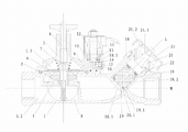
Fig. 1 is the structural representation of anti-siphon refluence guide electromagnetic valve of the present invention.
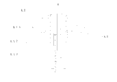
Fig. 2 is the structure for amplifying schematic representation of 8 parts among Fig. 1.
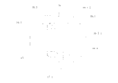
Fig. 3 is the structure for amplifying schematic representation of 16 parts among Fig. 1.
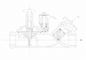
Structural representation when Fig. 4 is the closed electromagnetic valve of anti-siphon refluence guide electromagnetic valve of the present invention.
Fig. 5 is the structural representation that the solenoid valve of anti-siphon refluence guide electromagnetic valve of the present invention manually is opened.
Shown in the figure: 1, main valve body, 1.1, epicoele, 1.2, cavity of resorption, 2, main valve plug, 3, the main valve lid, 4, valve rod, 5, main valve seat; 6, septum assembly, 7, the main valve Returnning spring, 8, guidance set, 8.1, directional post, 8.1.1, guide pillar body, 8.1.2, guide column sleeve, 8.1.3, guide pillar Returnning spring; 8.2, flip sleeve, 9, through hole, 10, electromagnetic valve body, 10.1, guide's cavity, 11, newel, 12, electromagnetic coil; 13, armature, 14, sealing seat, 15, runner, 16, manually open control valve unit, 16.1, running shaft, 16.1.1, groove; 16.1.2 scrobicular ring radially, 16.2, turning lever, 16.3, seal ring, 16.4, bolt, 17, holding cavity, 17.1, bolt hole; 18, valve body, 18.1, import, 18.2, outlet, 19, spool, 19.1, sealing gasket, 20, valve seat; 20.1, bulge loop (convexity), 21, valve gap, 21.1, axial passage, 21.2, the radial passage, 22, Returnning spring, 23, dust-proof cover.
Embodiment
Below in conjunction with accompanying drawing and specific embodiment the present invention is described further.
See also shown in Figure 1ly, anti-siphon refluence guide electromagnetic valve of the present invention comprises main valve, the solenoid valve that is fixedly connected with main valve and the one-way valve that is connected with main valve.
Described main valve comprises main valve body 1, main valve plug 2, main valve lid 3 and valve rod 4.Described main valve lid 3 is located on the described main valve body 1, and described main valve plug 2 is located in the described main valve body 1, and described valve rod 4 is located on the described main valve lid 3.Also be provided with main valve seat 5 in the described main valve plug 2.Be provided with septum assembly 6 between described main valve seat 5 and the main valve lid 3, described septum assembly 6 is divided into epicoele 1.1 and cavity of resorption 1.2 with the cavity in the described main valve body 1, and described epicoele 1.1 and cavity of resorption 1.2 are connected through pipeline.Be supported with main valve Returnning spring 7 between described septum assembly 6 and the main valve lid 3.Described main valve plug 2 is installed between septum assembly 6 and the main valve seat 5 and described main valve plug 2 is connected with septum assembly 6.Also be provided with in the described main valve and make septum assembly 6 and main valve plug 2 guidance set that do not squint in the position when moving up and down 8.Described guidance set 8 comprises directional post 8.1 and flip sleeve 8.2.Described septum assembly 6 and main valve plug 2 all are fixed on the flip sleeve 8.2, and described flip sleeve 8.2 is linked in outside the described directional post 8.1, and described directional post 8.1 is fixed on the lower end of valve rod 4.Described directional post 8.1, flip sleeve 8.2 and valve rod 4 coaxial lines.Described directional post 8.1 comprises guide pillar body 8.1.1, guide column sleeve 8.1.2 and guide pillar Returnning spring 8.1.3.The lower end of described guide column sleeve 8.1.2 is fixed in the described main valve body 1, and the upper end of described guide column sleeve 8.1.2 is contained in the described slip 8.2.The upper end of described guide pillar body 8.1.1 is fixed on the lower end of described valve rod 4, and described guide pillar body 8.1.1 is contained in the described flip sleeve 8.2 and the lower end of guide pillar body 8.1.1 is contained in the guide column sleeve 8.1.2.Described guide pillar Returnning spring 8.1.3 is supported on the lower end of described guide pillar body 8.1.1, and promptly described guide pillar Returnning spring 8.1.3 is supported between guide pillar body 8.1.1 and the main valve body 1.Described epicoele 1.1 and cavity of resorption 1.2 are connected through the gap between flip sleeve 8.2 and the guide column sleeve 8.1.2.Described epicoele 1.1 sidewalls are provided with through hole 9, and this through hole 9 is communicated with guide's cavity 10.1 of solenoid valve.
Described solenoid valve comprises electromagnetic valve body 10, newel 11, be located at the outer electromagnetic coil 12 of newel 11 and be located at the armature 13 of newel 11 lower ends.Described armature 13 belows are provided with sealing seat 14 and described sealing seat 14 is located in the described electromagnetic valve body 10.The lower end of described solenoid valve is provided with the runner 15 that is communicated with described cavity of resorption 1.2, and described runner 15 is located at sealing seat 14, and this runner 15 is communicated with guide's cavity 10.1 of solenoid valve, and described guide's cavity 10.1 is electromagnetic valve body 10 inner chambers.Described armature 13 is moved up and down by electromagnetic coil 12 effects, and moving upward makes armature 13 break away from sealing seat 14, moves downward to make armature 13 sealing sealing seats 14.Described solenoid valve also is provided with and is used for manually making armature 13 to break away from manually opening control valve unit 16 and be located at and being used for the ccontaining holding cavity 17 that manually opens control valve unit 16 on the electromagnetic valve body 10 of sealing seats 14.One end of described holding cavity 17 is communicated with guide's cavity 10.1 of solenoid valve, and the other end of described holding cavity 17 is in communication with the outside.The described control valve unit 16 that manually opens is contained in the described holding cavity 17.The described control valve unit 16 that manually opens comprises running shaft 16.1 and turning lever 16.2.Described running shaft 16.1 can circumferentially be rotatably installed in the holding cavity 17, seals through seal ring 16.3 between described running shaft 16.1 and the holding cavity 17.Described turning lever 16.2 laterally is located on the interior edge face of described running shaft 16.1.When running shaft 16.1 rotated and drives turning lever 16.2 and turns to lengthwise position, described turning lever 16.2 backs down armature 13 made armature 13 break away from sealing seats 14.The outer end of described running shaft 16.1 is provided with the groove 16.1.1 that can be connected with rotatable handle.Described running shaft 16.1 circumferentially is rotatably installed in the holding cavity 17 and is meant; Described holding cavity 17 sidewalls are provided with bolt hole 17.1; Described running shaft 16.1 sidewalls are provided with radially scrobicular ring 16.1.2, and the upper end that is combined with bolt 16.4 and this bolt 16.4 in the described bolt hole 17.1 is contained in the described radially scrobicular ring 16.1.2 running shaft 16.1 axial limitings and running shaft 16.1 is rotated in a circumferential direction.
Described one-way valve comprises valve body 18, spool 19 and the valve seat 20 that is provided with import 18.1 and outlet 18.2.The import 18.1 of valve body 18 is communicated with described cavity of resorption 1.2, and described valve seat 20 is located in the described valve body 18; In; Described valve body 18 is provided with gas channel, and described gas channel is communicated with valve body 18 inner chambers; Described spool 19 supports through Returnning spring 22; When the one-way valve valve is closed; Spool 19 supports through Returnning spring 22 and is against described valve seat 20 upper sealing valve seats 20, and when the one-way valve valve was opened, spool 19 supported through Returnning spring 22 and is against sealed gas passageway on the gas channel inner port.In this specific embodiment, described one-way valve and described main valve are one-body molded.Described one-way valve is located on the described main valve obliquely.The axis M of the axis L of the valve body of described one-way valve and the main valve body of main valve intersects; The sidewall of described valve body 18 is located in the outlet 18.1 of valve body 18.Described one-way valve also is provided with valve gap 21, and described valve gap 21 is located on the described valve body 18, and described gas channel is located on the described valve gap 21; Described Returnning spring 22 is supported between spool 19 and the valve gap 21; Described gas channel comprises that described axial passage 21.1 is connected with radial passage 21.2 along valve gap 21 axial axial passages 21.1 that are provided with and communicate with extraneous and valve body 18 inner chambers and the radial passage 21.2 that radially is provided with and is in communication with the outside along valve gap 21.Described valve gap 21 outer ends are provided with dust-proof cover 23; Described dust-proof cover 23 is blocked the external port of described axial passage 21.1 and is covered the external port of described radial passage 21.2; The described external port that covers described radial passage is meant that dust-proof cover can block dust and get into the radial passage, but the radial passage still is connected with the external world; Gas can get into axial passage from the radial passage, gets into the one-way valve intracoelomic cavity from axial passage again.The valve seat inboard of described one-way valve is provided with bulge loop 20.1 or is evenly distributed with at least two convexities 20.1; Described spool (19) is provided with sealing gasket 19.1 with valve seat 20 contacted end faces, and described sealing gasket 19.1 is against on described bulge loop 20.1 or protruding 20.1.
The working principle of anti-siphon refluence guide electromagnetic valve of the present invention is:
When the electromagnetic coil no electric circuit, armature and sealing seat sealing, solenoid valve is in closed condition; The water of main valve body import flows into cavity of resorption; The water of cavity of resorption flows to the top (being epicoele) of septum assembly from the gap between guide column sleeve and the flip sleeve, when main valve body epicoele and cavity of resorption pressure balance, receive the main valve action of reset spring; Septum assembly moves down main valve plug is contacted with main valve seat, and main valve is closed.
When electromagnetic coil is switched on; Armature is moved upward by the electromagnetic coil effect and makes armature disengaging sealing seat; The water of main valve epicoele flows into cavity of resorption (main valve body outlet port) through the guide's cavity of described through hole, solenoid valve and the runner of solenoid valve; The pressure of main valve epicoele moves on the septum assembly and makes main valve plug and main valve seat disengaging, main valve open less than the pressure of main valve cavity of resorption at this moment.
When outage need be opened main valve, make turning lever go to lengthwise position through rotatable handle rotation running shaft, turning lever backs down armature makes armature break away from sealing seat, so just can open main valve.
When upstream pressure during less than downstream pressure; The pressure at check valve inlet place will be less than the pressure in one-way valve outlet port; At this moment, the one-way valve spool can be against on the valve seat by the effect of Returnning spring, when spool during gradually near valve seat; Spool will be gradually away from the gas channel inner port; When spool and gas channel inner port broke away from, gas can get in the one-way valve valve body through gas channel and destroy flow channel for liquids, thereby reached the purpose that prevents the siphon refluence causes resource to avoid the polluted water resource waste.Guide electromagnetic valve of the present invention; Under the situation that upstream pressure can normally be closed less than downstream pressure and main valve; One-way valve can improve the effect that the anti-siphon of guide electromagnetic valve is flow backwards, under the situation that upstream pressure can't normally be closed less than downstream pressure and valve, because gas channel has gas to get into; Destroyed fluid passage, the water behind the valve can not flow backwards in siphon yet.