CN102527823A - Fin trimming device for steering wheel of automobile - Google Patents
Fin trimming device for steering wheel of automobile Download PDFInfo
- Publication number
- CN102527823A CN102527823A CN2012100230907A CN201210023090A CN102527823A CN 102527823 A CN102527823 A CN 102527823A CN 2012100230907 A CN2012100230907 A CN 2012100230907A CN 201210023090 A CN201210023090 A CN 201210023090A CN 102527823 A CN102527823 A CN 102527823A
- Authority
- CN
- China
- Prior art keywords
- spoke
- spring
- group
- cushion block
- briquetting
- Prior art date
- Legal status (The legal status is an assumption and is not a legal conclusion. Google has not performed a legal analysis and makes no representation as to the accuracy of the status listed.)
- Granted
Links
Images


Abstract
A fin trimming device for a steering wheel of an automobile belongs to the technical field of molds and comprises an upper mold mechanism and a lower mold mechanism matched with the upper mold mechanism. The upper mold mechanism comprises an upper mold frame, a cutter fixing board, a group of outer ring cutter blocks, a group of inner ring cutter blocks and a spoke rim pressing ring. The lower mold mechanism comprises a lower mold frame, a spoke cutter fixing board, a plurality of groups of spoke cutters, a gasket board, a group of spoke rim pressing ring gaskets and a group of spoke pressing block gaskets. The fin trimming device has the advantages of being capable of not only saving labor input and reducing working intensity of workers but also remarkably improving eliminating efficiency and effect on fins.
Description
Technical field
The invention belongs to technical field of mold, be specifically related to a kind of vehicle steering and repair the overlap device
Background technology
such as industry the reason of knowledge, no matter be extrusion forming or die cast or all can stay the technology overlap with the vehicle steering of other similar fashion such as casting forming, the technology overlap is also claimed the technology slitter edge, must remove.And then such as industry the reason of knowledge, vehicle steering is made up of annular ring, spoke seat and spoke, the spoke seat is positioned at the central authorities of annular ring substantially, spoke is connected between spoke seat and the annular ring.Though the steering wheel of different vehicle there are differences; But macrostructure is essentially identical; Promptly all having annular ring (also claiming the spoke wheel rim), spoke seat and spoke, only is that spoke has two of being each other that in-line distributes or three of distribution triangular in shape substantially.
prior art generally with artificial mode promptly by manual to the overlap on the inside and outside edge of the annular ring that residues in the steering wheel base substrate and residue in the flash removal on the spoke.The self-evident shortcoming of manual removal overlap is: working strength of workers is big, operating efficiency is low and completeness is promptly lost in the difficult quality guarantee of deburring; And manual clear overlap also is attended by the danger of operation; Because overlap is irregularity both; Very sharp again, owe the careful limbs that then very easily undermine the workman slightly and particularly point.
are though as the attribute that the overlap device has mould of repairing of steering wheel; But the characteristics that have frock clamp simultaneously; So-called frock clamp is meant that being used for work in-process positions and/or clamping workpiece, to reach the special equipment of certain technological requirement.And, requirement such as frock clamp need satisfy when when production or to structure member, carrying out shaping does not usually have interference, accurate positioning is reliable and easy to operate.Again, because frock clamp has exclusive to the processing of certain product, so the generalization degree is extremely low, often by manufacturer's self manufacture of producing product.Just be based on this reason; Few about the technical information of repairing the overlap device of vehicle steering in present disclosed patent and non-patent literature if stars; Only CN201760487U recommends to have " a kind of vehicle steering trim mode "; Though this patent scheme has the 0007th section alleged technique effect of its specification; But only can be to the flash removal on the outward flange of the annular ring of steering wheel, then powerless for the inward flange and the overlap on the spoke of annular ring, and in this patent specification, do not provide the enlightenment of removing these overlaps yet.Therefore, in follow-up process, still need rely on the manual removal overlap.
In view of above-mentioned prior art, the applicant has done long-term and useful design, and under the secrecy provision of strictness, proves practicable through experiment, and the technical scheme that will introduce below produces under this background
Summary of the invention
task of the present invention is to provide a kind of and helps the overlap on the inside and outside edge of the annular ring that residues in the steering wheel base substrate and residue in overlap on the spoke to realize disposable removing and use and practice thrift human input, alleviate working strength of workers, improve operating efficiency and help ensureing that the vehicle steering of the thorough effect of flash removal repaiies the overlap device.
task of the present invention is accomplished like this, and a kind of vehicle steering is repaiied the overlap device, comprises mold mechanism and the following mold mechanism that is used for matching with last mold mechanism; Last mold mechanism comprises top mold frame, cutterhead fixed head, one group of outer ring cutterhead piece, one group of inner ring cutterhead piece and a spoke wheel rim trim ring, respectively has a guider in top mold frame towards a side of said mold mechanism down and four bights being positioned at top mold frame, and each guider matches with following mold mechanism; Cutterhead fixed head and top mold frame are fixed towards a said side of mold mechanism down; One group of outer ring cutterhead piece and cutterhead fixed head are fixed, and wherein, one group of outer ring cutterhead piece circularizes arranging corresponding to the outside of inner ring cutterhead piece; And this group outer ring cutterhead piece respectively constitutes one first circular arc blade towards a side of inner ring cutterhead piece; One group of inner ring cutterhead piece is with annular arrangement, and is formed with a spoke briquetting seat chamber at middle section, and each inner ring cutterhead piece constitutes one second circular arc blade towards a side of the said first circular arc blade; Wherein: constitute spoke briquetting chamber between one group of inner ring cutterhead piece; And between inside and outside circle cutterhead piece, maintain spoke wheel rim trim ring chamber, spoke wheel rim trim ring is placed in the said spoke wheel rim trim ring chamber, and this spoke wheel rim trim ring has one group of spoke briquetting that is spaced apart from each other and one group of spoke briquetting seat; The spoke briquetting is formed on the spoke briquetting seat; Be connected with spoke wheel rim trim ring and match, and spoke briquetting seat matches with said spoke briquetting seat chamber, wherein with described spoke briquetting chamber; Between spoke briquetting adjacent one another are, constitute an inner ring cutterhead piece chamber, described inner ring cutterhead piece matches with inner ring cutterhead piece chamber; Described mold mechanism down comprises mould bases, spoke cutter fixed head, plural groups spoke cutter, cushion block plate, one group of spoke wheel rim trim ring cushion block and one group of spoke briquetting cushion block down; Respectively be fixed with one towards four angles of a side of described top mold frame and in position at following mould bases and be used to the fairlead that supplies guider to match corresponding to said guider; Spoke cutter fixed head is fixed on down on the mould bases; The group number of spoke cutter equates with the quantity of described spoke briquetting cushion block; It is a pair of that every group of spoke cutter has, and a side that faces each other of every pair of spoke cutter constitutes a spoke blade, and maintains spoke cushion block chamber each other; Cushion block plate floating ground cooperates with spoke cutter fixed head; One group of spoke wheel rim trim ring cushion block each interval is fixed on the said cushion block plate and is circle distribution around the outside of spoke briquetting cushion block, and each spoke wheel rim trim ring cushion block is corresponding to described spoke wheel rim trim ring chamber, and one group of spoke briquetting cushion block is fixed on the central authorities of cushion block plate; Corresponding with said spoke briquetting; Wherein: respectively offering spoke tool bore chamber on the cushion block plate and between adjacent spoke briquetting cushion block, described spoke cutter probes in the spoke tool bore chamber, and matches with said spoke briquetting cushion block.
are in a concrete embodiment of the present invention; Described guider comprises guide pillar and stage clip, and guide pillar is fixed on the described top mold frame with cantilever position, and this guide pillar constitutes the guide pillar head of a diameter greater than the diameter of guide pillar towards a said end of mould bases down; This guide pillar head matches with described fairlead; Stage clip is nested with on guide pillar, and an end bearing of this stage clip is on last crossbearer, and the other end is bearing on the guide pillar head.
are in another concrete embodiment of the present invention; On described top mold frame and following the position in said guide pillar to be installed with the limited post that quantity equates with the quantity of guide pillar with cantilever position, each limited post is with said mould bases is corresponding down.
are in another concrete embodiment of the present invention; Respectively being installed with one back to the edge of a side of said cutterhead fixed head and in the position that faces each other in described top mold frame is used for and the fixing mould bases fixing feet of stamping machine; And in top mold frame back to a side of cutterhead fixed head and between corresponding to a pair of mould bases fixing feet, be provided with one first floating installation, this first floating installation is connected with described spoke wheel rim trim ring.
are in another concrete embodiment of the present invention; Described first floating installation comprises one first spring bearer plate, one first spring seat board, a pair of first gripper shoe and one group of first spring; The parallel setting of a pair of first gripper shoe; The top and the said top mold frame of each first gripper shoe are fixed; The bottom is fixed with first spring bearer plate, and first spring seat board is between the top mold frame and first spring bearer plate, and one group of first spring is between first spring bearer plate and first spring seat board; One end bearing of each spring is on first spring seat board; The other end is bearing on first spring bearer plate, wherein: on first spring seat board and in the position corresponding to said spoke wheel rim trim ring, with circumference state fixed interval one group of first push rod arranged, each first push rod passes said top mold frame successively and is connected with described spoke wheel rim trim ring with the cutterhead fixed head.
also have among the concrete embodiment of the present invention; Constitute first supporting cavity that quantity equates with the quantity of first spring towards a side of said first spring bearer plate and in position at described first spring seat board corresponding to said first spring; And constitute second supporting cavity that quantity equates with the quantity of first spring equally towards a side of first spring seat board and corresponding to the position of first spring at first spring bearer plate; One end bearing of spring is in first supporting cavity, and the other end is bearing in second supporting cavity.
are more of the present invention and among concrete embodiment; Respectively be installed with one back to the edge of a side of said spoke cutter fixed head and in the position that faces each other at described down mould bases and be used for the mould bases pin that matches with stamping machine; And between corresponding to a pair of mould bases pin, be provided with one second floating installation, this second floating installation is connected with described cushion block plate.
are in of the present invention and then concrete embodiment, in a side of described mould bases pin outward and offer one along its length and be used for and locating slot that stamping machine is fixing.
are of the present invention again more and among concrete embodiment; Described second floating installation comprises second spring bearer plate, one group of second spring and a pair of second gripper shoe, the parallel setting of a pair of second gripper shoe; Top of each second gripper shoe and described mould bases are down fixed; And the bottom and second spring bearer plate are fixed; The upper end of one group of second spring is passed described mould bases down successively and spoke cutter fixed head is bearing on the said cushion block plate; And the lower end of second spring is bearing on second spring bearer plate; Wherein: on following mould bases and at the surrounding edge bit interval corresponding to described cushion block plate, be equipped with one group of floating bolt, the upper end of this group floating bolt is connected with the cushion block plate after passing said spoke cutter fixed head, and the lower end of floating bolt is limited in down between mould bases and described second spring bearer plate.
are in again of the present invention and then concrete embodiment; Constitute the spring-loaded chamber that quantity equates with the quantity of second spring towards a side of said spoke cutter fixed head and in position at said cushion block plate corresponding to said second spring; And on second spring bearer plate and in position, constitute the 3rd supporting cavity that quantity equates with the quantity of second spring equally corresponding to second spring; The upper end of second spring is bearing in the said spring-loaded chamber, and the lower end is bearing in the 3rd supporting cavity.
technical scheme provided by the invention can be simultaneously by being fitted to each other of upper and lower mold mechanism with overlap and the disposable excision of the overlap on the spoke on the inside and outside edge of the annular ring of steering wheel base substrate; Thereby not only can practice thrift human input and alleviate workman's working strength, and can significantly improve elimination efficiency and effect overlap.
Description of drawings
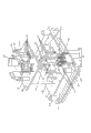
Fig. 1 repaiies the structure chart of overlap device for vehicle steering of the present invention.
Fig. 2 is the detailed structure view of last mold mechanism after being inverted 180 ° shown in Figure 1.
Fig. 3 is the structure chart of following mold mechanism shown in Figure 1.
The specific embodiment
can be expressly understood technical spirit of the present invention and beneficial effect more for the auditor that the makes Patent Office especially public; The applicant general elaborates with the mode of embodiment below; But the description to embodiment all is not the restriction to the present invention program, any according to the present invention design done only for pro forma but not substantial equivalent transformation all should be regarded as technical scheme category of the present invention.
please be referring to Fig. 1 to Fig. 3, and wherein, Fig. 2 will go up mold mechanism 1 with respect to user mode or claimed with respect to the installment state conversion of reality 180 ° position for the ease of clear understanding of the public.When reality was used, last mold mechanism 1 was fixedly connected with the oil cylinder post of stamping machine, and mold mechanism 2 is fixed with the workbench of stamping machine down.
Fig. 1 and Fig. 2 please be seen by emphasis in
; The aforesaid mold mechanism 1 of going up comprises a top mold frame 11, one piece of cutterhead fixed head 12, one group of outer ring cutterhead piece 13, one group of inner ring cutterhead piece 14 and spoke wheel rim trim ring 15; Top mold frame 11 is essentially the metallic plate of one piece of square or cuboid (present embodiment is a square); In this top mold frame 11 towards a side of aforesaid down mold mechanism 2 and be positioned at four bights and respectively be provided with a guider 111; Each guider 111 comprises a guide pillar 1111 and a stage clip 1112; Guide pillar 1111 is fixed in the bight of top mold frame 11 with cantilever position, constitutes the diameter guide pillar head 11111 bigger than the diameter of guide pillar 1111 at the end of this guide pillar 1111, around guide pillar head 11111, is provided with ball with high density state.Stage clip 112 is nested with on guide pillar 1111, and an end bearing of this stage clip 1112 is on top mold frame 11, and the other end then is bearing on the guide pillar head 1111.By (Fig. 1 and Fig. 2) shown in the figure, on top mold frame 11 and in position, more properly say in position to be installed with a limited post 112 with cantilever position equally near aforesaid guide pillar 1111 near aforesaid each guider 111.Cutterhead fixed head 12 adopts screw to be fixed on the side of top mold frame 11 towards following mold mechanism 2, between aforesaid four guiders 1111.One group of outer ring cutterhead piece 13 respectively adopts first hold-down screw 132 to be fixed on cutterhead fixed head 12 towards a side of mold mechanism 2 down, and one group of outer ring cutterhead piece 13 is enclosed circle in the central region of cutterhead fixed head 12.One group of inner ring cutterhead piece 14 equally respectively adopts second hold-down screw 145 to be fixed on the side of cutterhead fixed head 12 towards following mold mechanism 2; And being surrounded by aforesaid one group of outer ring cutterhead piece 13, also is that this group inner ring cutterhead piece 14 is positioned at the inboard of one group of outer ring cutterhead piece 13 in other words.Shown in figure; This group inner ring cutterhead piece 14 is fixed on the cutterhead fixed head 12 with the state of enclosing circumference each other; And between one group of inner ring cutterhead piece 14, also remain with three spoke piece chambeies 142; And be arranged with a spoke briquetting seat chamber 143 at the middle section of inner ring cutterhead piece 14, and between inner ring cutterhead piece 14 and outer ring cutterhead piece 13, maintain the annular channel of a perforation, constitute spoke wheel rim trim ring chamber 144 by this annular channel.Constitute one first circular arc blade 131 at each outer ring cutterhead piece 13 towards a side of inner ring cutterhead piece 14, equally the side at each inner ring cutterhead piece 14 cutterhead piece 13 towards the outer ring constitutes one second circular arc blade 141.Spoke wheel rim trim ring 15 is placed in the aforesaid spoke wheel rim trim ring chamber 144; In the present embodiment; Spoke wheel rim trim ring 15 has three spoke briquettings 151 and three spoke briquetting seats 152; Each spoke briquetting 151 constitutes integrative-structure with spoke briquetting seat 152 and is connected with spoke wheel rim trim ring 15, constitutes an inner ring cutterhead piece chamber 1511 between the adjacent spoke briquetting 151, and aforesaid inner ring cutterhead piece 14 is placed in the inner ring cutterhead piece chamber 1511.
after in spoke wheel rim trim ring 15 the is placed in aforesaid spoke wheel rim trim ring chamber 144,151 of aforesaid spoke briquettings are corresponding to promptly being placed in the spoke briquetting chamber 142, in the spoke briquetting seat 152 then located spoke briquetting seat chambeies 143.
like the applicant described in the background technology; The version of the spoke of vehicle steering is not quite similar; For example spoke has and is a pair of that in-line or V font distribute each other; Three (three) that distribution triangular in shape is substantially also arranged; Therefore why having three spoke briquetting chambeies 142 and three spoke briquettings 151 in the present embodiment, is because to the steering wheel with three spokes, therefore can not limit technical scheme of the present invention with the number change of spoke briquetting chamber 142 and spoke briquetting 151 accordingly.
Fig. 1 and Fig. 2 are still seen in
; Respectively be fixed with a mould bases fixing feet 113 in top mold frame 11 back to a side of cutterhead fixed head 12 and at the marginal position that faces each other; That is to say in the edge of the forward and backward side of the top mold frame 11 of present location status shown in Figure 1 and respectively be fixed with a mould bases fixing feet 113; This is used for not shown but be connected according to the oil cylinder post that professional general knowledge can be understood the hydraulic jack of the stamping machine that fully mould bases fixing feet 113; Specifically be to set oil cylinder cylinder seat at the end of oil cylinder post, more a pair of mould bases fixing feet 113 fixed with oil cylinder cylinder seat.
in top mold frame 11 back to a side of aforesaid cutterhead fixed head 12 and between corresponding to a pair of mould bases fixing feet 113, be provided with one first floating installation 3; This first floating installation 3 preferably but not the structure that definitely is limited to is following: comprise first spring bearer plate 31, first spring seat board 32, a pair of first gripper shoe 33 and one group of first spring 34; A pair of first gripper shoe 33 parallel (corresponding about also can claiming each other); The top of the length direction of each first gripper shoe 33 and the edge of aforesaid top mold frame 11 are fixed; And the bottom of length direction is fixing through the 3rd hold-down screw 331 and first spring bearer plate 31 of Fig. 2 signal; That is to say that wherein one piece of first gripper shoe 33 in a pair of first gripper shoe 33 is fixed on the left side between the top mold frame 11 and first spring bearer plate 31, another piece first gripper shoe 3 then is fixed on the right side between the top mold frame 11 and first spring bearer plate 31.First spring seat board 32 is movably between the top mold frame 11 and first spring bearer plate 31; One end of one group of first spring 32 is that lower end shown in Figure 1 also is that upper end shown in Figure 2 is bearing on first spring seat board 32, also is that lower end shown in Figure 2 is bearing on first spring bearer plate 31 and the other end of one group of first spring 32 is upper end shown in Figure 1.Preferably; Be concaved with first supporting cavity 322 that quantity equates with the quantity of first spring 34 towards a side of first spring bearer plate 31 and in position at first spring seat board 32, and be concaved with second supporting cavity 311 that quantity equates with the quantity of first spring 34 towards a side of first spring seat board 32 and in position corresponding to first supporting cavity 322 at first spring bearer plate 31 corresponding to first spring 34.One end bearing of aforesaid first spring 34 is in first supporting cavity 322, and the other end is bearing in second supporting cavity 311.Thereby by 34 pairs first spring seat board 31 floating supports of one group of first spring.
are fixed with one group of first push rod 321 with circle distribution and with the interval state on aforesaid first spring seat board 32 and in the position corresponding to aforesaid spoke wheel rim trim ring 15, this is organized to be stretched over behind the second push rod resigning hole 121 of first push rod 321 on passing the first push rod resigning hole 114 that is opened on the top mold frame 11 successively and being opened in cutterhead fixed head 12 and defaults in the push rod connecting hole 153 on the spoke wheel rim trim ring 15 and be connected with spoke wheel rim trim ring 15.In the present embodiment, owing on spoke wheel rim trim ring 15, have 12 push rod connecting holes 153 at interval, therefore the quantity of first push rod 321 has 12, but does not receive the restriction of present embodiment quantity.
Fig. 1 and Fig. 2 please referring to Fig. 3 and be continued to combine in
; The detailed following mold mechanism 2 that shows Fig. 1 signal in Fig. 3; This time mold mechanism 2 comprises mould bases 21, one piece of spoke cutter fixed head 22, plural groups spoke cutter 23, a cushion block plate 24, one group of spoke wheel rim trim ring cushion block 25 and one group of spoke briquetting pad 26; The geometry of following mould bases 21 is as the description to top mold frame 11; Towards a side of top mold frame 11 and be positioned at four bights and respectively be installed with a fairlead 211, the guide pillar head 11111 of aforementioned guide pillar 1111 matches with fairlead 211, promptly is insinuated in the fairlead 211 at following mould bases 21.Again; Following mould bases 21 towards under the edge of front and back side respectively be fixed with a mould bases pin 212; And the middle position at the length direction of each mould bases pin 212 outward respectively offers a locating slot 2121; Instantly the workbench (also can claim work top) of mould bases 21 and stamping machine is fixedly the time, can be with being fixed in L shaped on the workbench or claiming that the angle of 7 fonts hooks in the locating slot 2121, so that mould bases 21 is positioned on the workbench of stamping machine reliably.Spoke cutter fixed head 22 preferred screw and the following mould bases 21 of using are fixed towards a side of last mold mechanism 1, and integrally between aforesaid four fairleads 211.The end of aforesaid limited post (four) is corresponding with the edge of following mould bases 21, and when the end of limited post 112 touched down mould bases 21, it was no longer descending then to go up mold mechanism 1, in the hope of fetch protection.Plural groups spoke cutter 23 is fixed by bolts to the middle position of spoke cutter fixed head 22 towards a side of last mold mechanism 1, in the present embodiment, because as aforementioned; Be to vehicle steering with three spokes; Therefore spoke cutter 23 has three groups, and every group has a pair ofly, and each side that faces each other to spoke cutter 23 constitutes spoke blade 231; And maintain spacing between every pair of spoke cutter 23, constitute spoke cushion block chamber 232 by this spacing.Cushion block plate 24 is substantially the structure of square (square); Be stacked on the spoke cutter fixed head 22 with quick condition; One group of spoke wheel rim trim ring cushion block 25 is arranged at intervals on the cushion block plate 24 through the 4th hold-down screw 252 with the circle distribution state; Specifically: each spoke wheel rim trim ring cushion block 25 has a cushion block seat 251; The bottom of each cushion block seat 251 and cushion block plate 24 are fixing, and spoke wheel rim trim ring cushion block 25 directly is formed in the top of cushion block seat 251, and each spoke wheel rim trim ring cushion block 25 matches with aforesaid spoke wheel rim trim ring chamber 144.One group of spoke briquetting cushion block 26 is fixed on the central authorities of cushion block plate 24; Surround by aforesaid one group of spoke wheel rim briquetting cushion block 25; The quantity of one group of spoke briquetting cushion block 26 is three of connecting of one (because present embodiment is to the vehicle steering with three spokes), and is corresponding with aforesaid spoke briquetting 151.By shown in Figure 3; Respectively constituting (offering) spoke tool bore chamber 241 on the aforesaid cushion block plate 24 and between adjacent spoke briquetting cushion block 26; When cushion block plate 24 is stacked to 22 last times of spoke cutter fixed head; Spoke cutter 23 just probes into spoke tool bore chamber 241, and spoke briquetting cushion block 26 matches with spoke cushion block chamber 232.
please continue to see Fig. 3 and combine Fig. 1; Aforesaid down mould bases 21 towards under a side promptly be equipped with one second floating installation 4 back to a side of spoke cutter fixed head 22 and between corresponding to a pair of mould bases pin 212; This second floating installation 4 preferably but not the structure that definitely is limited to is following: comprise one second spring bearer plate 41, a plurality of i.e. one group of second spring 42 and a pair of second gripper shoe 43; A pair of second gripper shoe 43 is parallel promptly to correspond to each other; The top of the length direction of each second gripper shoe 43 is fixed with following mould bases 21, and the bottom of length direction is fixing through the 5th hold-down screw 431 and second spring bearer plate 41.That is to say that wherein one piece of second gripper shoe 43 in a pair of second gripper shoe 43 is fixed on down between the left side of the mould bases 21 and second spring bearer plate 41, another piece second gripper shoe 43 then is fixed on down between the right side of the mould bases 21 and second spring bearer plate 41.One end of one group of spring 42 is that the upper end of shown position state is supported on the aforesaid cushion block plate 24 after passing the first spring resigning hole 214 that is opened on the following mould bases 21 successively and being opened in the second spring resigning hole 221 on the spoke cutter fixed head 22, and the other end of second spring 42 to be illustrated lower end be bearing on second spring bearer plate 41.Preferably; Be concaved with the quantity of second spring 42 towards a side of spoke cutter fixed head 22 at cushion block plate 24 and equate and corresponding spring-loaded chamber, position (not shown); And on second spring bearer plate 41 and same be concaved with the 3rd supporting cavity 411, the second springs 42 that quantity equates with second spring 42 in the position corresponding to second spring 42 and be supported in spring-loaded chamber and the 3rd supporting cavity 411.
are by shown in Figure 3; On following mould bases 21 and be equipped with one group of floating bolt 213 corresponding to the position, edge of aforesaid cushion block plate 24 four bights of cushion block plate 24 (preferably corresponding to); The upper end of each floating bolt 213 is connected with cushion block plate 24 behind the floating bolt resigning hole that passes on the down mould bases 21 and spoke cutter fixed head 22; And that portion's (stub end) is established through the expansion of lower end in the lower end of floating bolt 231 is spacing down between the mould bases 21 and second spring bearer plate 41, realizes that therefrom cushion block plate 24 is stacked and placed on the spoke cutter holder 22 with quick condition.
applicant describes operation principle of the present invention, and the fixed form of at first the following mould bases 21 of top mold frame 11 that goes up mold mechanism 1 of the present invention and following mold mechanism 2 having been mentioned according to the applicant in the above is set on stamping machine such as the punch press.The steering wheel that has overlap 5 with the dashed line form signal among Fig. 1 is placed down on the mold mechanism 1; And the loop type circle 51 that makes steering wheel 5 is corresponding to promptly being shelved on the spoke wheel rim trim ring cushion block 25 on the spoke wheel rim trim ring cushion block 25; At this moment, the spoke 52 on the steering wheel 25 just has been shelved on the spoke briquetting cushion block 26.Stamping machine work is ordered about mold mechanism 1 towards the direction displacement of mold mechanism 2 down by stamping machine, and until the annular ring 51 that makes spoke wheel rim trim ring 25 pressures and steering wheel 5, and the while is pressed by spoke briquetting 151 and the spoke 52 of steering wheel 5.Then stamping machine makes mold mechanism 1 to bottom offset according to the course of action of program setting then; So; In this process by second, the first circular arc blade 141,131 on the inside and outside circle cutterhead piece 14,13 and under the acting in conjunction of spoke wheel rim trim ring cushion block 25 with the overlap excision of the medial and lateral of the annular ring 51 of steering wheel 5, simultaneously by under the spoke blade 231 of the spoke cutter 23 of mold mechanism 2 down and spoke briquetting cushion block 26 these threes' the common cooperation with the eliminating flap edges (excision) on the spoke 52 of steering wheel 5.Die sinking makes mold mechanism 1 scold out with respect to following mold mechanism 2, gets from the steering wheel that has excised overlap 5.
In sum, technical scheme provided by the invention has overcome the shortcoming in the prior art, has accomplished the invention task, has objectively embodied described technique effect
Claims (10)
1.
a kind of vehicle steering is repaiied the overlap device; It is characterized in that the following mold mechanism (2) that comprises mold mechanism (1) and be used for matching with last mold mechanism (1); Last mold mechanism (1) comprises top mold frame (11), cutterhead fixed head (12), one group of outer ring cutterhead piece (13), one group of inner ring cutterhead piece (14) and a spoke wheel rim trim ring (15); Respectively has a guider (111) in top mold frame (11) towards a side of said down mold mechanism (2) and four bights being positioned at top mold frame (11); Each guider (111) matches with following mold mechanism (2), and cutterhead fixed head (12) is fixed towards a said side of mold mechanism (2) down with top mold frame (11), and one group of outer ring cutterhead piece (13) is fixing with cutterhead fixed head (12); Wherein, One group of outer ring cutterhead piece (13) circularizes arranging corresponding to the outside of inner ring cutterhead piece (14), and this group outer ring cutterhead piece (13) respectively constitutes one first circular arc blade (131) towards a side of inner ring cutterhead piece (14), and one group of inner ring cutterhead piece (14) is with annular arrangement; And be formed with a spoke briquetting seat chamber (143) at middle section; Each inner ring cutterhead piece (14) constitutes one second circular arc blade (141) towards a side of the said first circular arc blade (131), wherein: constitute spoke briquetting chamber (142) between one group of inner ring cutterhead piece (14), and between inside and outside circle cutterhead piece (14,13), maintain spoke wheel rim trim ring chamber (144); Spoke wheel rim trim ring (15) is placed in the said spoke wheel rim trim ring chamber (144); This spoke wheel rim trim ring (15) has one group of spoke briquetting (151) that is spaced apart from each other and one group of spoke briquetting seat (152), and spoke briquetting (151) is formed on the spoke briquetting seat (152), is connected with spoke wheel rim trim ring (15) and matches with described spoke briquetting chamber (142); And spoke briquetting seat (152) matches with said spoke briquetting seat chamber (143); Wherein, between spoke briquetting (151) adjacent one another are, constitute an inner ring cutterhead piece chamber (1511), described inner ring cutterhead piece (14) matches with inner ring cutterhead piece chamber (1511); Described mold mechanism (2) down comprises mould bases (21), spoke cutter fixed head (22), plural groups spoke cutter (23), cushion block plate (24), one group of spoke wheel rim trim ring cushion block (25) and one group of spoke briquetting cushion block (26) down; Respectively be fixed with one towards four angles of a side of described top mold frame (11) and in position at following mould bases (21) and be used to the fairlead (211) that supplies guider (111) to match corresponding to said guider (111); Spoke cutter fixed head (22) is fixed on down on the mould bases (21); The group number of spoke cutter (23) equates with the quantity of described spoke briquetting cushion block (26); Every group of spoke cutter (23) has a pair of; A side that faces each other of every pair of spoke cutter (23) constitutes a spoke blade (231); And maintain spoke cushion block chamber (232) each other, cushion block plate (24) floating ground cooperates with spoke cutter fixed head (22), and one group of spoke wheel rim trim ring cushion block (25) each interval is fixed on that said cushion block plate (24) is gone up and is circle distribution around the outside of spoke briquetting cushion block (26); Each spoke wheel rim trim ring cushion block (25) is corresponding to described spoke wheel rim trim ring chamber (144); One group of spoke briquetting cushion block (26) is fixed on the central authorities of cushion block plate (24), and is corresponding with said spoke briquetting (151), wherein: go up and between adjacent spoke briquetting cushion block (26), respectively offer spoke tool bore chamber (241) at cushion block plate (24); Described spoke cutter (23) probes in the spoke tool bore chamber (241), and matches with said spoke briquetting cushion block (26).
2.
vehicle steering according to claim 1 is repaiied the overlap device; It is characterized in that described guider (111) comprises guide pillar (1111) and stage clip (1112); Guide pillar (1111) is fixed on the described top mold frame (11) with cantilever position; And this guide pillar (1111) constitutes the guide pillar head (11111) of a diameter greater than the diameter of guide pillar (1111) towards a said end of mould bases (21) down, and this guide pillar head (11111) matches with described fairlead (211), and stage clip (1112) is nested with on guide pillar (1111); One end bearing of this stage clip (1112) is on last crossbearer (11), and the other end is bearing on the guide pillar head (11111).
3.
vehicle steering according to claim 1 is repaiied the overlap device; It is characterized in that going up and following the position in said guide pillar (1111) to be installed with the limited post (112) that quantity equates with the quantity of guide pillar (1111) with cantilever position in described top mold frame (11), each limited post (112) is corresponding with said time mould bases (21).
4.
vehicle steering according to claim 1 is repaiied the overlap device; It is characterized in that respectively being installed with one back to the edge of a side of said cutterhead fixed head (12) and in the position that faces each other in described top mold frame (11) is used for and the fixing mould bases fixing feet (113) of stamping machine; And in top mold frame (11) back to a side of cutterhead fixed head (12) and between corresponding to a pair of mould bases fixing feet (113), be provided with one first floating installation (3), this first floating installation (3) is connected with described spoke wheel rim trim ring (15).
5.
vehicle steering according to claim 4 is repaiied the overlap device; It is characterized in that described first floating installation (3) comprises one first spring bearer plate (31), one first spring seat board (32), a pair of first gripper shoe (33) and one group of first spring (34); The parallel setting of a pair of first gripper shoe (33); Top of each first gripper shoe (33) and said top mold frame (11) are fixing; The bottom is fixing with first spring bearer plate (31); First spring seat board (32) is positioned between top mold frame (11) and first spring bearer plate (31); One group of first spring (34) is positioned between first spring bearer plate (31) and first spring seat board (32), and an end bearing of each spring is on first spring seat board (32), and the other end is bearing on first spring bearer plate (31); Wherein: upward and in the position corresponding to said spoke wheel rim trim ring (15) with circumference state fixed interval one group of first push rod (321) arranged at first spring seat board (32), each first push rod (321) passes said top mold frame (11) successively and is connected with described spoke wheel rim trim ring (15) with cutterhead fixed head (12).
6.
vehicle steering according to claim 5 is repaiied the overlap device; It is characterized in that constituting first supporting cavity (322) that quantity equates with the quantity of first spring (34) towards a side of said first spring bearer plate (31) and in position corresponding to said first spring (34) at described first spring seat board (32); And constitute second supporting cavity (311) that quantity equates with the quantity of first spring (34) equally towards a side of first spring seat board (32) and corresponding to the position of first spring (34) at first spring bearer plate (31); One end bearing of spring (34) is in first supporting cavity (322), and the other end is bearing in second supporting cavity (311).
7.
vehicle steering according to claim 1 is repaiied the overlap device; It is characterized in that respectively being installed with one back to the edge of a side of said spoke cutter fixed head (22) and in the position that faces each other at described down mould bases (21) is used for the mould bases pin (212) that matches with stamping machine; And between corresponding to a pair of mould bases pin (212), be provided with one second floating installation (4), this second floating installation (4) is connected with described cushion block plate (24).
8.
vehicle steering according to claim 7 is repaiied the overlap device, it is characterized in that in a side of described mould bases pin (212) outward and offer one along its length being used for and locating slot (2121) that stamping machine is fixing.
9.
vehicle steering according to claim 7 is repaiied the overlap device; It is characterized in that described second floating installation (4) comprises second spring bearer plate (41), one group of second spring (42) and a pair of second gripper shoe (43), the parallel setting of a pair of second gripper shoe (43); Top of each second gripper shoe (43) and described mould bases (21) are down fixed; And bottom and second spring bearer plate (41) are fixing; The upper end of one group of second spring (42) is passed described mould bases (21) down successively and spoke cutter fixed head (22) is bearing on the said cushion block plate (24); And the lower end of second spring (42) is bearing on second spring bearer plate (41); Wherein: upward and at surrounding edge bit interval be equipped with one group of floating bolt (213) corresponding to described cushion block plate (24) at following mould bases (21); The upper end of this group floating bolt (213) is connected with cushion block plate (24) after passing said spoke cutter fixed head (22), and the lower end of floating bolt (213) is limited in down between mould bases (21) and described second spring bearer plate (41).
10.
Vehicle steering according to claim 9 is repaiied the overlap device; It is characterized in that constituting the spring-loaded chamber that quantity equates with the quantity of second spring (42) towards a side of said spoke cutter fixed head (22) and in position corresponding to said second spring (42) at said cushion block plate (24); And go up and constitute equally the 3rd supporting cavity (411) that quantity equates with the quantity of second spring (42) in position corresponding to second spring (42) at second spring bearer plate (41); The upper end of second spring (42) is bearing in the said spring-loaded chamber, and the lower end is bearing in the 3rd supporting cavity (411)
Priority Applications (1)
| Application Number | Priority Date | Filing Date | Title |
|---|---|---|---|
| CN 201210023090 CN102527823B (en) | 2012-02-02 | 2012-02-02 | Fin trimming device for steering wheel of automobile |
Applications Claiming Priority (1)
| Application Number | Priority Date | Filing Date | Title |
|---|---|---|---|
| CN 201210023090 CN102527823B (en) | 2012-02-02 | 2012-02-02 | Fin trimming device for steering wheel of automobile |
Publications (2)
| Publication Number | Publication Date |
|---|---|
| CN102527823A true CN102527823A (en) | 2012-07-04 |
| CN102527823B CN102527823B (en) | 2013-08-28 |
Family
ID=46336548
Family Applications (1)
| Application Number | Title | Priority Date | Filing Date |
|---|---|---|---|
| CN 201210023090 Active CN102527823B (en) | 2012-02-02 | 2012-02-02 | Fin trimming device for steering wheel of automobile |
Country Status (1)
| Country | Link |
|---|---|
| CN (1) | CN102527823B (en) |
Cited By (1)
| Publication number | Priority date | Publication date | Assignee | Title |
|---|---|---|---|---|
| CN108857396A (en) * | 2018-08-01 | 2018-11-23 | 苏州戴米克自动化科技有限公司 | A kind of belt pulley press-loading apparatus |
Families Citing this family (1)
| Publication number | Priority date | Publication date | Assignee | Title |
|---|---|---|---|---|
| CN107138594A (en) * | 2017-03-07 | 2017-09-08 | 芜湖仅机械有限公司 | A kind of steering wheel die casting cast gate rushes stamping die tool |
Citations (4)
| Publication number | Priority date | Publication date | Assignee | Title |
|---|---|---|---|---|
| CN201720332U (en) * | 2010-06-13 | 2011-01-26 | 奇瑞汽车股份有限公司 | Automobile covering trimming waste cut-off mould |
| CN201791815U (en) * | 2010-09-30 | 2011-04-13 | 鑫鸿交通工业(安徽)有限公司 | Shearing die for metal plate of automobile |
| CN201832892U (en) * | 2010-11-05 | 2011-05-18 | 上海德真工贸有限公司 | Side shearing die for left and right back wheel covers of vehicle |
| CN202479320U (en) * | 2012-02-02 | 2012-10-10 | 江苏中翼汽车新材料科技有限公司 | Flash trimming device of steering wheel of car |
-
2012
- 2012-02-02 CN CN 201210023090 patent/CN102527823B/en active Active
Patent Citations (4)
| Publication number | Priority date | Publication date | Assignee | Title |
|---|---|---|---|---|
| CN201720332U (en) * | 2010-06-13 | 2011-01-26 | 奇瑞汽车股份有限公司 | Automobile covering trimming waste cut-off mould |
| CN201791815U (en) * | 2010-09-30 | 2011-04-13 | 鑫鸿交通工业(安徽)有限公司 | Shearing die for metal plate of automobile |
| CN201832892U (en) * | 2010-11-05 | 2011-05-18 | 上海德真工贸有限公司 | Side shearing die for left and right back wheel covers of vehicle |
| CN202479320U (en) * | 2012-02-02 | 2012-10-10 | 江苏中翼汽车新材料科技有限公司 | Flash trimming device of steering wheel of car |
Cited By (1)
| Publication number | Priority date | Publication date | Assignee | Title |
|---|---|---|---|---|
| CN108857396A (en) * | 2018-08-01 | 2018-11-23 | 苏州戴米克自动化科技有限公司 | A kind of belt pulley press-loading apparatus |
Also Published As
| Publication number | Publication date |
|---|---|
| CN102527823B (en) | 2013-08-28 |
Similar Documents
| Publication | Publication Date | Title |
|---|---|---|
| CN204818848U (en) | Machine tool machining anchor clamps | |
| CN204053781U (en) | The contour grinding clamp of many drifts | |
| CN203649124U (en) | Punching die for channel steel hole system for longitudinal beam of conveyer middle frame | |
| CN202479320U (en) | Flash trimming device of steering wheel of car | |
| CN204799733U (en) | Duplex position shearing and punching machine | |
| CN102527823B (en) | Fin trimming device for steering wheel of automobile | |
| CN105107931A (en) | Punching and deburring device for motorcycle hub spoke holes | |
| CN104959465A (en) | Automobile covering part trimming device | |
| CN202479321U (en) | Flash-cutting device of automobile steering wheel | |
| CN205056814U (en) | Cut -out press is cut to side of half shell of admitting air | |
| CN102581115B (en) | Flash cutting device for steering wheels of automobiles | |
| CN203635740U (en) | Centralized punching mold for radiating fins | |
| CN208245587U (en) | A kind of oil pipe bracket progressive die | |
| CN203030711U (en) | Punching machining die of transverse beam installing plate of instrument panel | |
| CN104368699A (en) | Punching die for left main arm rod and right main arm rod | |
| CN102873206B (en) | Pipe clamp stamping die | |
| CN105750396A (en) | Channel steel arc cutting mold | |
| CN106111781A (en) | Channel tie manufactures one-time-shaped mould | |
| CN105500067A (en) | Transverse-plane straight-cutting tool clamp of cutting machine | |
| CN203380248U (en) | Blanking die of motor silicon steel sheet | |
| CN104368844A (en) | Plate punching clamp | |
| CN205043000U (en) | Major diameter round steel is processed into mould of U -shaped spare | |
| CN203649123U (en) | Punching die for channel steel hole system for longitudinal beam of conveyer middle frame | |
| CN204220772U (en) | Off-chip punching progressive die | |
| CN203459498U (en) | Punching die for rib plates of railway trucks |
Legal Events
| Date | Code | Title | Description |
|---|---|---|---|
| C06 | Publication | ||
| PB01 | Publication | ||
| C10 | Entry into substantive examination | ||
| SE01 | Entry into force of request for substantive examination | ||
| C14 | Grant of patent or utility model | ||
| GR01 | Patent grant |