CN102502418B - Special equipment and method for turning container door - Google Patents
Special equipment and method for turning container door Download PDFInfo
- Publication number
- CN102502418B CN102502418B CN201110298911.3A CN201110298911A CN102502418B CN 102502418 B CN102502418 B CN 102502418B CN 201110298911 A CN201110298911 A CN 201110298911A CN 102502418 B CN102502418 B CN 102502418B
- Authority
- CN
- China
- Prior art keywords
- freight container
- suspension gear
- truck
- container
- lifting mechanism
- Prior art date
- Legal status (The legal status is an assumption and is not a legal conclusion. Google has not performed a legal analysis and makes no representation as to the accuracy of the status listed.)
- Active
Links
Images


Abstract
The invention relates to a technology for turning a container door for container docks or storage yards and in particular relates to a realizing method of a novel special equipment for turning a container door. The special equipment comprises a lifting mechanism, a suspending mechanism and a stander on which the lifting mechanism, transverse moving mechanism and the suspending mechanism are arranged, and is characterized in that the turning of the container door is realized by transverse moving the container and making the truck a u-turn. According to the invention, the one-time investment and maintenance cost is reduced greatly, the energy is saved, the consumption is reduced, the pollution is avoided, the use reliability is improved greatly, and the operation safety is guaranteed.
Description
Technical field
The present invention relates to container wharf or stockyard in order to turn the technology of chamber door of container, specifically a kind of position with miniaturization is fixing is exclusively used in the equipment of turning chamber door of container and realizes the method for turning chamber door of container.
Background technology
When freight container is contained on truck, chamber door is not towards on often affecting handling and the shipment of article in case.Therefore at each harbour and stockyard, all have the equipment of turning chamber door of container that is specifically designed to.
The conventional means of turning chamber door of container have four kinds at present: the one, and directly utilize gauntry crane to adjust the freight container of chamber door to sling need, truck is outputed one-lane truck passage in the district of meter Chang Xiang more than 200, a rear reverse driving of turning round is driven back to gauntry crane below, and gauntry crane is put into freight container on car and completes and change chamber door action.Its shortcoming is the gauntry crane that needs the value of using to surpass 7,000,000 yuan, and disposable input is very large, safeguards that accordingly use cost is high again.Simultaneously truck reverse driving in narrow bicycle road truck passage, this truck is very big with the risk that other truck of forward travel that is strayed into Gai Xiang district bumps against, and has very large potential safety hazard!
The 2nd, utilize gauntry crane to mix rotary hanger and realize., be that the hanger for container that gauntry crane changes chamber door by need is sling, for preventing that freight container from toppling in lifting or rotary course, first with the traversing method of suspender by freight container center of gravity be adjusted to suspender center under, then rise and winch on a container height, hanger twist turnback, then freight container is put on truck car.This method is than first method advantage, and it is mobile that whole process truck does not need to turn around not need, and efficiency is high.Shortcoming is that one-time investment is large.Except gauntry crane, also need to buy special rotary hanger, and also will do corresponding transformation to gauntry crane software and hardware, expense is at least more than 8,000,000 yuan.
The 3rd, use at present maximum modes: utilize front handling mobile crane, directly change chamber door.Front handling mobile crane itself just has this function.But front handling mobile crane one-time investment higher (at least more than 4,000,000 yuan), and expend the diesel oil of costliness in short supply, use cost is very high.
The 4th, utilize fixed type to adjust the special gauntry crane of chamber door of container directly to change chamber door.Use fixed type to adjust the special gauntry crane of chamber door of container, this gauntry crane fixes on the ground, and its top is provided with can be around the frame of round circular orbit operation.Frame is provided with large-scale hoisting drum and driver train.While changing chamber door, fixedly hang first and with suspender, freight container is sling, after Rotate 180 degree, freight container is placed on truck again and completes and change chamber door action.This method one-time investment and use cost, than several method is few above, are the most reasonable at present, and the minimum a kind of mode of integrated cost.But its equipment one-time investment at least also needs more than 3,600,000 yuan.
In view of the disposable of existing method means has high input, working service cost is high, the oil plant that also expends costliness in short supply having.One can guaranteed efficiency and is greatly reduced disposable input and maintenance cost, and can save energy free of contamination, significantly to improve reliability of service new turning, to change chamber door of container Apparatus for () and method therefor be that people expect.
Summary of the invention
The object of the invention is to make up above-mentioned defect, to society, disclose a kind of less investment, energy-saving and cost-reducing, the low specialized equipment that increases substantially again operating reliability of pollution-free cost is realized the method for turning chamber door of container.
Technical scheme of the present invention is:
Be exclusively used in an equipment of turning chamber door of container, comprise: lifting mechanism, suspension gear, arrange the frame of lifting mechanism, suspension gear; It is characterized in that: in described frame, be also provided with transverse-moving mechanism, this transverse-moving mechanism has comprised rolling or the slide unit of guiding load-bearing effect and made the drive element of transverse-moving mechanism transverse shifting; Described frame is relatively fixing in lengthwise position.
The rolling of described transverse-moving mechanism or slide unit are road wheel or heavy slide block, and drive element is that oil cylinder or motor reducer directly drive.
The described lifting mechanism of being located in frame is: for promoting screw motor or oil cylinder or the small-sized cable drum lifting drive element of freight container.
Described frame is integral-rack or former and later two independent rack, and during two independent rack, the lifting mechanism, transverse-moving mechanism and the suspension gear that are connected with it are also relatively independent.
Described suspension gear comprises: comprise and revolve suspender, steel rope or the soft rope of lock, open locking parts or the parts of chain or pull bar suspension weight.
Use the described method of turning chamber door of container that is exclusively used in, it is characterized in that it comprises the following steps:
1) freight container that the truck that is loaded with freight container is turned chamber door by need be pulled to described suspension gear under;
2) described lifting mechanism moves down with suspension gear, and the lock that revolves on suspension gear inserts after freight container lockhole, revolves lock and has rotated block action, and freight container and suspension gear combine as a whole;
3) described lifting mechanism work, described suspension gear is with moving on freight container, until freight container and truck depart from completely;
4) described traversing actuation mechanism work, makes freight container transverse shifting, until freight container shifts out the maximum outer contour of truck;
5) truck is outputed and is mixed up after head, then car is left back, makes on truck to be placed in due to the room that freight container is vacateed after removing the side-lower of the freight container being lifted;
6) described transverse-moving mechanism task again, makes the horizontal travelling backwards of freight container, until freight container move to truck room directly over;
7) described lifting mechanism work, moves down the freight container under suspension gear and this suspension gear, until the lockhole under freight container penetrates on the lock pin of truck, and complete case; The lock that revolves on suspension gear has rotated unlocking action, and suspension gear and freight container are thrown off;
8) described lifting mechanism, with moving on described suspension gear, departs from described suspension gear and freight container completely, and the truck of having turned container door drives away.
Advantage of the present invention is:
Rely on transverse-moving mechanism, freight container is laterally shifted out, omitted extremely complexity and expensive swing type mechanism of structure, greatly reduce one-time investment.
Changing in chamber door process, cancelled freight container has been risen to an action more than chamber door, reduced the lifting altitude of freight container, eliminated freight container and smashed the risk of truck.
And this method time used be less than existing all methods, efficiency is also guaranteed.
The device structure of implementing this method is simple, and single-minded solution chamber door of container is turned problem, makes whole equipment realize miniaturization, and cost of manufacture is significantly reduced, and every manufacturing cost lowers more than 80% than the most cheap existing congenerous equipment.And easy to maintenance, maintenance cost significantly reduces.
The equipment of implementing this method is used relatively cheap civil power for the energy, and use cost is cheap, has realized again fuel-economizing, low consumption, has also avoided environmental pollution.
Accompanying drawing explanation
Fig. 1 is apparatus embodiments 1 schematic diagram of the present invention (front view);
Fig. 2 is the left view of Fig. 1;
Fig. 3 is the birds-eye view of Fig. 1;
Fig. 4 is apparatus embodiments 2 schematic diagrams of the present invention (front view);
Fig. 5 is the left view of Fig. 4;
Fig. 6 is the birds-eye view of Fig. 4;
Fig. 7 is apparatus embodiments 3 schematic diagrams of the present invention (front view);
Fig. 8 is the left view of Fig. 7;
Fig. 9 is the birds-eye view of Fig. 7;
Figure 10 is apparatus embodiments 4 schematic diagrams of the present invention (front view);
Figure 11 is the left view of Figure 10;
Figure 12 is the birds-eye view of Figure 10;
Figure 13 is the schematic diagram of transverse-moving mechanism of the present invention take oil cylinder as drive force frame;
Figure 14 is lifting mechanism of the present invention drives lifting mechanism schematic diagram by screw motor;
Figure 15 is lifting mechanism of the present invention drives lifting mechanism schematic diagram by small-sized reel;
Figure 16 be the truck that is loaded with freight container enter suspension gear under schematic diagram;
Figure 17 is freight container and the suspension gear schematic diagram that combines as a whole;
Figure 18 is that freight container and truck depart from schematic diagram completely;
Figure 19 is the traversing actuation mechanism work of the present invention, makes freight container transverse shifting, until freight container shifts out the maximum outer contour schematic diagram of truck;
Figure 20 opens back the side-lower schematic diagram that is placed in the freight container being lifted after truck mixes up head;
Figure 21 freight container moves to schematic diagram directly over truck room;
Figure 22 is that freight container moves down and complete case, and suspension gear and freight container are thrown off schematic diagram;
Figure 23 is that suspension gear and freight container depart from completely, the truck of the having turned chamber door of container schematic diagram that drives away.
The specific embodiment
Each Reference numeral title in accompanying drawing is:
Below in conjunction with embodiment, the present invention is described in further detail:
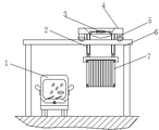
As Figure 1-3, a kind of equipment of turning chamber door of container that is exclusively used in, comprising: lifting mechanism 3, suspension gear 2, arrange the frame 4 of lifting mechanism, suspension gear; It is characterized in that: in described frame 4, be also provided with transverse-moving mechanism 5, this transverse-moving mechanism has comprised rolling or the slide unit of guiding load-bearing effect and made the drive element of transverse-moving mechanism transverse shifting.Described frame is relatively fixing in lengthwise position.
The present embodiment frame 4 is integral-racks.On four cement beam columns 6, be two cement beams parallel to each other, on cement beam, establish track 51.Integral-rack is across on two cement beams parallel to each other.It under frame, is road wheel 52.This road wheel 52 makes frame 4 transverse shifting on track 51 under the motor reducer 53 of transverse-moving mechanism directly drives.Described frame 4 is relative fixing in longitudinal (with freight container parallel direction) position.
Should indicate: also can replace road wheel and track with heavy slide block and slide rail, drive element can be also that oil cylinder, screw mandrel or sprocket wheel chain or rack-and-gear replace motor reducer herein.
The lifting mechanism of being located in frame 4 is the lifting pulley 33 that oil cylinder 31, steel rope 23 and conversion for promoting freight container are used by force direction.
In frame 4, oil cylinder 31 drive element both sides also can arrange and can make the vert oil cylinder 34 that verts of use of suspender, to facilitate suspender and freight container or freight container and truck contraposition.
The method of using the said equipment to turn chamber door of container is that it comprises the following steps:
1) freight container that the truck 1 that is loaded with freight container 7 is turned chamber door by need be pulled to described suspension gear 2 under (Figure 16);
2) described lifting mechanism 3 moves down with suspension gear 2, and the revolving lock on suspension gear inserts after freight container lockhole, revolves lock and rotate block action, freight container 7 and suspension gear 2 combine as a whole (Figure 17);
3) described lifting mechanism 3 is worked, and described suspension gear 2 is with moving on freight container 7, until freight container and truck 1 depart from (Figure 18) completely;
4) described traversing actuation mechanism 5 is worked, and makes freight container 7 transverse shiftings, until freight container shifts out the maximum outer contour (Figure 19) of truck 1;
5) truck 1 is outputed and is mixed up after head, then car is left back, makes on truck to be placed in due to the room that freight container 7 is vacateed after removing the side-lower (Figure 20) of the freight container 7 being lifted;
6) described transverse-moving mechanism 5 task again, makes freight container 7 horizontal
returnmove, until freight container move to truck 1 room directly over (Figure 21);
7) described lifting mechanism 3 is worked, and the freight container 7 under suspension gear 2 and this suspension gear is moved down, until the lockhole under freight container penetrates on the lock pin of truck 1, and complete case; The lock that revolves on described suspension gear 2 has rotated unlocking action, makes suspension gear 2 and freight container 1 throw off (Figure 22);
8) described lifting mechanism 3 is with moving on described suspension gear 2, and described suspension gear 2 is departed from completely with freight container 1, the truck of having turned container door drive away (Figure 23).
As Figure 4-Figure 6, the Apparatus and operation method of embodiment 2 and embodiment 1 are roughly the same.Difference is, frame 4 bottoms are provided with column, and the track 51 of transverse-moving mechanism 5 is established on the ground, and its flat travelling wheel 52 and motor reducer 53 are located at below, is that the transverse shifting of the frame 4 with the column suspension gear 2 that made to hoist drives freight container 7 traversing.
As Figure 7-9, a kind of equipment of turning chamber door of container that is exclusively used in, comprising: lifting mechanism 3, suspension gear 2, arrange the frame 4 of lifting mechanism, suspension gear; It is characterized in that: in described frame 4, be also provided with transverse-moving mechanism 5.Described frame is relatively fixing in lengthwise position.
The present embodiment frame 4 is former and later two independent rack, and the lifting mechanism, transverse-moving mechanism and the suspension gear that are connected with it are also relatively independent.Two frames 4 are parallel and be located at respectively on cement beam column 6.It under frame, is traveling wheel 52.This traveling wheel makes two frames 4 transverse shifting on track 51 under the motor reducer 53 of transverse-moving mechanism directly drives.Described frame 4 is relative fixing in longitudinal (with freight container parallel direction) position.
The lifting mechanism of being located in frame 4 is the lifting pulley 33 that oil cylinder 31 lifting drive elements, steel rope 23 and conversion for promoting freight container are used by force direction.
Described suspension gear 2 comprises: comprise the also easy Manual hanger of standard suspender 21(that revolves lock, open locking parts), steel rope 23, pulley 22.
The using method of the present embodiment 3 equipment is identical with embodiment 1.
As shown in Figure 10-12, the Apparatus and operation method of embodiment 4 and embodiment 3 are roughly the same.The frame 4 of the present embodiment is also former and later two independent rack, and the lifting mechanism, transverse-moving mechanism and the suspension gear that are connected with it are also relatively independent.Frame 4 bottoms are provided with column as different from Example 3, and the track 51 of transverse-moving mechanism 5 is established on the ground, its flat travelling wheel 52 and motor reducer 53 are located at below, are that the transverse shifting of the frame 4 with the column suspension gear 2 that made to hoist drives freight container 7 traversing.The present embodiment is similar to embodiment 2 in this.
Also must supplement: the drive element of transverse-moving mechanism also can serve as (Figure 13) by sideslip oil cylinder 56.The drive element of lifting mechanism also can be by screw motor 35(Figure 14) or small-sized reel 36(Figure 15) serve as.
Claims (1)
1. one kind is exclusively used in the method for turning chamber door of container, the equipment of its use is to be exclusively used in the equipment of turning chamber door of container, described equipment comprises: lifting mechanism, suspension gear, lifting mechanism is set, the frame of suspension gear, described lifting mechanism is set up in frame and comprises screw motor or oil cylinder or the small-sized cable drum lifting drive element for promoting freight container, in described frame, be also provided with transverse-moving mechanism, described transverse-moving mechanism has comprised rolling or the slide unit of guiding load-bearing effect and has made the drive element of transverse-moving mechanism transverse shifting, described rolling or slide unit are road wheel or heavy slide block, described drive element is that oil cylinder or motor reducer directly drive, described frame is integral-rack or former and later two independent rack, the lifting mechanism being connected with frame, transverse-moving mechanism and suspension gear are also relatively independent, and described frame is relatively fixing in lengthwise position, described suspension gear comprises: comprise and revolve lock, the suspender of open locking parts, steel rope or soft rope or chain or pull bar hang the parts of weight, it is characterized in that comprising the following steps:
1) freight container that the truck that is loaded with freight container is turned chamber door by need be pulled to described suspension gear under;
2) described lifting mechanism moves down with suspension gear, and the lock that revolves on suspension gear inserts after freight container lockhole, revolves lock and has rotated block action, and freight container and suspension gear combine as a whole;
3) described lifting mechanism work, described suspension gear is with moving on freight container, until freight container and truck depart from completely;
4) described traversing actuation mechanism work, makes freight container transverse shifting, until freight container shifts out the maximum outer contour of truck;
5) truck is outputed and is mixed up after head, then car is left back, makes on truck to be placed in due to the room that freight container is vacateed after removing the side-lower of the freight container being lifted;
6) described transverse-moving mechanism task again, makes freight container horizontal
returnmove, until freight container move to truck room directly over;
7) described lifting mechanism work, moves down the freight container under suspension gear and this suspension gear, until the lockhole under freight container penetrates on the lock pin of truck, and complete case; The lock that revolves on suspension gear has rotated unlocking action, and suspension gear and freight container are thrown off;
8) described lifting mechanism, with moving on described suspension gear, departs from described suspension gear and freight container completely, and the truck of having turned chamber door of container drives away.
Priority Applications (1)
| Application Number | Priority Date | Filing Date | Title |
|---|---|---|---|
| CN201110298911.3A CN102502418B (en) | 2011-09-29 | 2011-09-29 | Special equipment and method for turning container door |
Applications Claiming Priority (1)
| Application Number | Priority Date | Filing Date | Title |
|---|---|---|---|
| CN201110298911.3A CN102502418B (en) | 2011-09-29 | 2011-09-29 | Special equipment and method for turning container door |
Publications (2)
| Publication Number | Publication Date |
|---|---|
| CN102502418A CN102502418A (en) | 2012-06-20 |
| CN102502418B true CN102502418B (en) | 2014-05-07 |
Family
ID=46214569
Family Applications (1)
| Application Number | Title | Priority Date | Filing Date |
|---|---|---|---|
| CN201110298911.3A Active CN102502418B (en) | 2011-09-29 | 2011-09-29 | Special equipment and method for turning container door |
Country Status (1)
| Country | Link |
|---|---|
| CN (1) | CN102502418B (en) |
Families Citing this family (3)
| Publication number | Priority date | Publication date | Assignee | Title |
|---|---|---|---|---|
| CN103601074B (en) * | 2013-11-25 | 2015-09-16 | 安迅捷集装箱码头(深圳)有限公司 | Gantry container crane and control method thereof |
| CN106530755A (en) * | 2016-12-19 | 2017-03-22 | 盐田国际集装箱码头有限公司 | Gantry crane container vehicle queuing container turn-around passage method |
| CN110422285A (en) * | 2019-08-09 | 2019-11-08 | 浙江海洋大学 | A kind of hanging apparatus for spitkit |
Citations (5)
| Publication number | Priority date | Publication date | Assignee | Title |
|---|---|---|---|---|
| US4715762A (en) * | 1983-02-24 | 1987-12-29 | Mi-Jack Products, Inc. | Grappler system for lifting apparatus |
| DE9108874U1 (en) * | 1991-07-19 | 1992-11-19 | O & K Orenstein & Koppel Ag, 1000 Berlin, De | |
| CN1090827A (en) * | 1992-11-11 | 1994-08-17 | 嫩青利布海尔·维克有限公司 | Crane in bridge type |
| DE10136398A1 (en) * | 2001-07-26 | 2003-03-06 | Siemens Ag | Operation of a container crane, involves determining position of spreader from positions of ground markings to enable automatic accurate positioning of the spreader |
| CN201172596Y (en) * | 2008-02-04 | 2008-12-31 | 交通部水运科学研究所 | Straddle type transportation vehicle for light-duty container |
-
2011
- 2011-09-29 CN CN201110298911.3A patent/CN102502418B/en active Active
Patent Citations (5)
| Publication number | Priority date | Publication date | Assignee | Title |
|---|---|---|---|---|
| US4715762A (en) * | 1983-02-24 | 1987-12-29 | Mi-Jack Products, Inc. | Grappler system for lifting apparatus |
| DE9108874U1 (en) * | 1991-07-19 | 1992-11-19 | O & K Orenstein & Koppel Ag, 1000 Berlin, De | |
| CN1090827A (en) * | 1992-11-11 | 1994-08-17 | 嫩青利布海尔·维克有限公司 | Crane in bridge type |
| DE10136398A1 (en) * | 2001-07-26 | 2003-03-06 | Siemens Ag | Operation of a container crane, involves determining position of spreader from positions of ground markings to enable automatic accurate positioning of the spreader |
| CN201172596Y (en) * | 2008-02-04 | 2008-12-31 | 交通部水运科学研究所 | Straddle type transportation vehicle for light-duty container |
Also Published As
| Publication number | Publication date |
|---|---|
| CN102502418A (en) | 2012-06-20 |
Similar Documents
| Publication | Publication Date | Title |
|---|---|---|
| CN201895084U (en) | Special casting truck for casting | |
| CN107010550A (en) | A kind of counterweight can adjust cantilever type rotating crane | |
| CN207415658U (en) | A kind of concrete material transfering device and preform production line | |
| CN102502418B (en) | Special equipment and method for turning container door | |
| CN207415665U (en) | A kind of preform production line | |
| CN107444859A (en) | One kind fermentation pallet track exchanging device and the method for improving that switches tracks | |
| CN102320079A (en) | Demoulding hook push ferrying vehicle | |
| CN203602254U (en) | Support frame for installing precast beam jack | |
| CN202877793U (en) | Turnover machine for welding frame of semitrailer | |
| CN202245406U (en) | Equipment specialized for turning chamber door of container | |
| CN202912586U (en) | Slewing crane for nuclear power plant | |
| CN2430233Y (en) | Steel ladle car | |
| CN216302687U (en) | Container loading, unloading and carrying device | |
| CN110065783A (en) | A kind of track crossings formula transport vehicle | |
| CN102649511B (en) | Railway gondola car loading system | |
| CN213416065U (en) | Transportation lifting device of train maintenance platform | |
| CN208216707U (en) | container switching moving flatcar | |
| CN209853582U (en) | Fine adjustment and shift system for crane trolley lifting appliance | |
| CN115916687A (en) | Gantry crane for containers and method of operation | |
| CN219669586U (en) | Train container unloading system | |
| CN110406918B (en) | Cloud-rail-based conveying system and gravity center calculation method for ten-thousand-ton-level load | |
| CN211687013U (en) | Double-layer kettle-discharging ferry vehicle | |
| CN108791318A (en) | A kind of mobile shipping cable car suitable for complicated landform | |
| CN116969098B (en) | Container terminal dense storage rapid loading and unloading system and operation method | |
| CN203821250U (en) | Hanging structure of one-armed box girder bridge erection machine |
Legal Events
| Date | Code | Title | Description |
|---|---|---|---|
| C06 | Publication | ||
| PB01 | Publication | ||
| C10 | Entry into substantive examination | ||
| SE01 | Entry into force of request for substantive examination | ||
| C14 | Grant of patent or utility model | ||
| GR01 | Patent grant |