CN102473027A - Accessible display in device with closed lid - Google Patents
Accessible display in device with closed lid Download PDFInfo
- Publication number
- CN102473027A CN102473027A CN2011800027352A CN201180002735A CN102473027A CN 102473027 A CN102473027 A CN 102473027A CN 2011800027352 A CN2011800027352 A CN 2011800027352A CN 201180002735 A CN201180002735 A CN 201180002735A CN 102473027 A CN102473027 A CN 102473027A
- Authority
- CN
- China
- Prior art keywords
- touch
- display
- screen
- electronic equipment
- described electronic
- Prior art date
- Legal status (The legal status is an assumption and is not a legal conclusion. Google has not performed a legal analysis and makes no representation as to the accuracy of the status listed.)
- Pending
Links
Images


Classifications
-
- G—PHYSICS
- G06—COMPUTING; CALCULATING OR COUNTING
- G06F—ELECTRIC DIGITAL DATA PROCESSING
- G06F1/00—Details not covered by groups G06F3/00 - G06F13/00 and G06F21/00
- G06F1/16—Constructional details or arrangements
-
- G—PHYSICS
- G06—COMPUTING; CALCULATING OR COUNTING
- G06F—ELECTRIC DIGITAL DATA PROCESSING
- G06F1/00—Details not covered by groups G06F3/00 - G06F13/00 and G06F21/00
- G06F1/16—Constructional details or arrangements
- G06F1/1613—Constructional details or arrangements for portable computers
- G06F1/1633—Constructional details or arrangements of portable computers not specific to the type of enclosures covered by groups G06F1/1615 - G06F1/1626
- G06F1/1637—Details related to the display arrangement, including those related to the mounting of the display in the housing
-
- G—PHYSICS
- G06—COMPUTING; CALCULATING OR COUNTING
- G06F—ELECTRIC DIGITAL DATA PROCESSING
- G06F1/00—Details not covered by groups G06F3/00 - G06F13/00 and G06F21/00
- G06F1/16—Constructional details or arrangements
- G06F1/1613—Constructional details or arrangements for portable computers
- G06F1/1615—Constructional details or arrangements for portable computers with several enclosures having relative motions, each enclosure supporting at least one I/O or computing function
- G06F1/1616—Constructional details or arrangements for portable computers with several enclosures having relative motions, each enclosure supporting at least one I/O or computing function with folding flat displays, e.g. laptop computers or notebooks having a clamshell configuration, with body parts pivoting to an open position around an axis parallel to the plane they define in closed position
-
- G—PHYSICS
- G06—COMPUTING; CALCULATING OR COUNTING
- G06F—ELECTRIC DIGITAL DATA PROCESSING
- G06F1/00—Details not covered by groups G06F3/00 - G06F13/00 and G06F21/00
- G06F1/16—Constructional details or arrangements
- G06F1/1613—Constructional details or arrangements for portable computers
- G06F1/1633—Constructional details or arrangements of portable computers not specific to the type of enclosures covered by groups G06F1/1615 - G06F1/1626
- G06F1/1684—Constructional details or arrangements related to integrated I/O peripherals not covered by groups G06F1/1635 - G06F1/1675
- G06F1/169—Constructional details or arrangements related to integrated I/O peripherals not covered by groups G06F1/1635 - G06F1/1675 the I/O peripheral being an integrated pointing device, e.g. trackball in the palm rest area, mini-joystick integrated between keyboard keys, touch pads or touch stripes
- G06F1/1692—Constructional details or arrangements related to integrated I/O peripherals not covered by groups G06F1/1635 - G06F1/1675 the I/O peripheral being an integrated pointing device, e.g. trackball in the palm rest area, mini-joystick integrated between keyboard keys, touch pads or touch stripes the I/O peripheral being a secondary touch screen used as control interface, e.g. virtual buttons or sliders
-
- G—PHYSICS
- G06—COMPUTING; CALCULATING OR COUNTING
- G06F—ELECTRIC DIGITAL DATA PROCESSING
- G06F3/00—Input arrangements for transferring data to be processed into a form capable of being handled by the computer; Output arrangements for transferring data from processing unit to output unit, e.g. interface arrangements
- G06F3/01—Input arrangements or combined input and output arrangements for interaction between user and computer
- G06F3/03—Arrangements for converting the position or the displacement of a member into a coded form
- G06F3/041—Digitisers, e.g. for touch screens or touch pads, characterised by the transducing means
- G06F3/0412—Digitisers structurally integrated in a display
-
- H—ELECTRICITY
- H04—ELECTRIC COMMUNICATION TECHNIQUE
- H04M—TELEPHONIC COMMUNICATION
- H04M1/00—Substation equipment, e.g. for use by subscribers
- H04M1/02—Constructional features of telephone sets
- H04M1/0202—Portable telephone sets, e.g. cordless phones, mobile phones or bar type handsets
- H04M1/026—Details of the structure or mounting of specific components
- H04M1/0266—Details of the structure or mounting of specific components for a display module assembly
-
- H—ELECTRICITY
- H04—ELECTRIC COMMUNICATION TECHNIQUE
- H04M—TELEPHONIC COMMUNICATION
- H04M1/00—Substation equipment, e.g. for use by subscribers
- H04M1/02—Constructional features of telephone sets
- H04M1/0202—Portable telephone sets, e.g. cordless phones, mobile phones or bar type handsets
- H04M1/0206—Portable telephones comprising a plurality of mechanically joined movable body parts, e.g. hinged housings
- H04M1/0208—Portable telephones comprising a plurality of mechanically joined movable body parts, e.g. hinged housings characterized by the relative motions of the body parts
- H04M1/0214—Foldable telephones, i.e. with body parts pivoting to an open position around an axis parallel to the plane they define in closed position
Abstract
Disclosed are electronic devices whereby a main display may be used even when the device is in a closed-lid position. In some embodiments, a window (display portion opening) may be provided in the device housing so that a portion of the display may be viewed when the lid is closed.
Description
Technical field
Relate generally to of the present invention has the electronic equipment of closing lid, and relates to the equipment that can see its display through closing lid especially.
Description of drawings
Through the mode of example rather than through for example clear this inventive embodiment of the mode of restriction, identical in the accompanying drawings Reference numeral refers to similar elements in the figure of accompanying drawing.
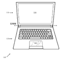
Fig. 1 is according to the uncap skeleton view of electronic equipment of position of being in of some embodiment.
Fig. 2 shows the equipment according to Fig. 1 that is in part closing lid position of some embodiment.
Fig. 3 shows the equipment according to Fig. 1 and 2 that is in the closing lid position of some embodiment.
Fig. 4 is the block diagram according to the computing system of the equipment that is suitable for Fig. 1-3 of some embodiment.
Fig. 5 A shows the display of the equipment of the Fig. 1-3 that is used to be in the pattern of uncapping.
But Fig. 5 B shows from Fig. 5 A display when equipment is in the closing lid pattern.
Embodiment
Many electronic equipments use so-called clam shell configuration, and the equipment that thus, is in " uncapping " position exposes basic display unit and user's input mechanism (such as keypad, touch pad or the like).On the other hand, (invisible) position that when equipment was in " closing lid " (folding) position, that display and user's input mechanism are in usually was shielded, can not see, and equipment also is closed power supply usually.For example, for many so-called notebooks and net book portable computer and for some cellular phone design, all be such situation.
Yet, for many users, need not their equipment be opened with normal mode and to the situation of its power supply under can be promptly and to use their equipment that is in the closing lid position effectively can be easily.Therefore; Some same time design comprises additional (assisting) littler display; Usually be positioned on the outside of the equipment when closed, go to see the information in the equipment such as appointed information, Email, instant message or the like thereby make the user need not open lid.Regrettably, this type of additional display has increased cost, and it possibly make their competitive power reduce.In addition, for these times closing lid display, it also possibly be supposed to provide the touch-screen of cooperating with display, and this has increased even more expense.
Therefore, in certain embodiments, disclosed is the electronic equipment that adopts clamshell type design, even when this equipment is in the closing lid position, also can use basic display unit thus.In certain embodiments, window (display part opening) can be provided in device housings thus make the part that can watch display when being closed when covering.
In certain embodiments; Said window can comprise the touch pad of being processed by transparent material; Thereby make the user using the touch pad on its back side mutual during the closing lid operator scheme, and can during the pattern of uncapping normally, use it from end face with the part that is shown.Therefore, when lid is closed, for example ought carry at that time, or expectation any other time when system not being powered up fully, the user can be able to see information from said equipment easily.
Fig. 1-3 shows the electronic equipment 100 (being notebook in this embodiment) with appreciable display part during the closing lid pattern.Portable computer 100 is made up of first and second housing parts 110,120 that rotatably are coupled at the jointed shaft place respectively usually.This first (being last clam shell part in this embodiment) comprises display 115.Indicator screen 115 can be selected from one or more display technologies that can easily obtain; For example, LCD (LCD), cathode ray tube (CRT), plasma scope, surface-conduction-electron emission display (SED) and Organic Light Emitting Diode (OLED).Certainly, can use the display technology of replacement and/or the display technology of developing later on.
Some manufacturer has used the OLED material recently.OLED is the technology by the Eastman Kodak company exploitation in the Rochester city in New York.They are radiative membraneous materials when being excited by electric current.Because the light of OLED emission different colours is so they can be used under the situation that does not need independent backlight, make display.The OLED display normally light and can under low relatively voltage, work effectively, therefore consume power still less from system.For some embodiment, display 115 can be by the OLED display or comprise have brightness separately the display of controlled pixel (pixel) form.
Second portion 120 (clam shell part under being in this embodiment) comprises the closing lid display aperture, and it is used transparent double-faced touch panel 122 in this embodiment and occupies.Like finding in Fig. 2 and 3, said lower part can also comprise that one or more input control button (or buttons) 124 are to be used to control and/or activate the equipment that is in the closing lid pattern.The physical Design of said lower part 120 combines said display part opening, and it can be similar to is the size of touch pad 122.In the embodiment that describes, this opening is approximate to be 80 millimeters of 100 millimeters x, but considers according to particular design, is used for during the closing lid pattern, watching the opening of display part can have any suitable shapes or size.
In certain embodiments, touch pad is two-sided, and it allows on the two sides, to touch control with this mode, when lid be open and user during in the display front, the end face of touch pad can be used to and computer interactive.On the other hand, when lid was closed, the user can use the back of the body (or the down) face of touch pad so that with mutual through the said part of the appreciable display of transparent touch pad.
When being two-sided, any suitable transparent touchpad technology that this touch pad (or touch-screen) can adopt permission on the two sides, to touch control realizes.For example, the first and second transparent touch plate materials can back-to-back be coupled, thereby make on their the touch-sensitive face one side in office all outwardly.They can comprise transparent material sheet material (such as the glass or the plastics that are clipped between the touch pad sheet material).In appointing on the one or both sides of touch-screen, touch-screen can be configured to generate I/O (I/O) signal in response to the tactile pressure of some position in touch-screen (for example, using contact pilotage, finger or the like to touch the specific part of this touch-screen).Alternatively, touch-screen can comprise transparent (for example, glass or the plastics) panel with touch-responsive surface.Touch-screen can be selected from a plurality of touch screen technologies that can easily obtain, for example, and pressure-sensitive (resistance), sound quick (surface wave), photosensitive (infrared) and electricity quick (for example, electric capacity) touch-screen.
Be noted that to have display aperture transparent, two-sided touch-screen, can also adopt other embodiment though embodiment has been described to adopt.In certain embodiments, can use the touch-screen with the only touch on one side control, perhaps touch-screen can be dispensed fully.For example, said opening can be empty, and perhaps it can comprise that transparent material (for example, plastics) covers opening and sealing prevents dust.
Alternatively, plastics or glass lens can cover this opening.In other embodiments, plastics privacy filtrator can cover this opening, thereby makes and will look like dark when display when certain angle is watched.In another embodiment, opaque slide lid can be used to protect this opening, and the duplicate protection that privacy and physics are provided is with scratch or infringement.
Fig. 4 is the block diagram that illustrates according to the example of the operable computer system of this inventive embodiment.This computer system can comprise CPU (CPU) or processor 402, and can receive its power from electrical socket or battery.CPU 402 can be coupled to chipset 410 via link 405.CPU 402 can be made by the Intel Company in for example California Santa Clara city, although it also can be by other manufactured.Any communication link of link 405 ordinary representations is such as the one or more point-to-point links that comprise a plurality of parallel routes and/or one or more buses.
For radio communication, the antenna (not shown) also can be coupled to wave point, and it also can be the part of chipset.Although not shown, other equipment (for example, keyboard, mouse or the like) also can be connected to chipset.This computer system can be used direct current (DC) power supply (such as, for example, battery).Alternatively, it can use interchange (AC) power supply through for example inserting plug in the electric connector.When computer system was in normal power mode, it can consume maximum power.When it is in low-power mode (for example, suspending or standby mode) or closing lid display mode, can consume less power, when using the DC power supply, this possibly be important.
It should be understood that for convenience's sake, show independent CPU and chip glomeration.Yet; In actual embodiment; CPU and chipset function can be in single chips (such as adopting the SOC embodiment) or adopt plurality of chips to realize, and can be fully cooperate and carry out different functions through independent functional block or with other pieces arbitrary or in the two in CPU and the chipset functional unit.For example, in some embodiments, storer and/or display can be coupled directly to CPU.CPU and chipset can comprise that various additional ports and/or link communicate by letter with the piece of being described or other pieces that does not illustrate being used for.
With reference to figure 5A and 5B, show complete demonstration and part demonstration, closing lid pattern.Fig. 5 A shows the computing machine that is in complete viewing areas 505 patterns, and Fig. 5 B shows the part viewing areas 510 of the power that only is used to reduce, the display of closing lid pattern.
In certain embodiments, during the closing lid pattern, only there is the part of display 115 to be switched on (for example, such as to OLED technology) or illuminate (such as to LED or LCD embodiment) from behind.
The viewing area 510 that reduces can have any suitable shapes, size and embodiment, watches although it should adapt to when lid is closed through said display part opening.For example, display 115 can have that have can be by the pixel of brightness of control individually.For an embodiment, when lid was closed, display controller 413 can comprise and be used for display message is limited to the only logic in viewing area 510.Can use different techniques to limit or shrink said information (or displaying contents) to be fit to littler viewing area.For an embodiment, displaying contents can be transmitted through the scaling logic in the display controller 413, and it is through with fractional multiplication and abandon any fractional value and change pixel.For example; When display controller 413 with the viewing area when full-size is reduced to the size as ten sixths of this full-size; In the row and column each can multiply by 0.25, and the row and column position can be transferred to reduce size see the zone in suitable row and column.
For an alternative embodiment, for example can use that video driver and operating system (OS) come with the said conversion of software executing, thereby make and to reduce displaying contents through legibility loss seldom.For example, OS can have " simply " pattern, and wherein the many graphics details on icon, toolbar or the like can be eliminated to save the space.This OS can have and can be switched to adapt to the brand-new user interface mode of littler viewing area, as normally used those that kind in mobile phone, PDA(Personal Digital Assistant) or the like.Interface protocol between display controller 413 and the display 115 (for example, Low Voltage Differential Signal (LVDS) interface) also can be enhanced to support this quasi-mode.For example, display controller 413 can only send a fraction of data that are used for said screen, and display 115 can use black (pixel is disconnected) to fill remaining areas.Can also be through sending many black picture elements on the interface, to save power by beard and hair.It is black that all pixels can be given tacit consent in new interface, only if sent data to this pixel.
The pixel that is associated with viewing area 510 can be configured to launch light or be switched on, and the pixel that is associated with remaining area can be configured to not launch light or be disconnected.
In typical embodiment, display part 510 images can appear by normal orientation.In another embodiment; Can use the standard software algorithm on display, to present said image with flipped image with reversing; Thereby make that when the user sees display reversing ground orientation simultaneously through display part opening from the computing machine back side said image will face up and by orientation rightly.In another embodiment, can use standard software algorithm image rotating of CW ground/withershins on LCD.In certain embodiments, whether sensing switch indication lid is closed, and can influence appear warning according to pattern.
In certain embodiments, for example, when message can be used for watching, indicator (LED) can be that the part of panel 124 is with warning users for example.In certain embodiments, one or more buttons can allow the user in the closing lid pattern, to watch message and/or browse them.In certain embodiments, (one or more) loudspeaker can be disposed on one or more edges of computing equipment, thereby makes that when covering be that the He Danggai that opens is closed this two the time, and they can both easily be heard.
In aforementioned description, many specific detail are set forth.Yet, should be understood that embodiments of the invention can be implemented under the situation of these specific detail not having.In other instance, for not fuzzy understanding of this description, known circuit, structure and technology possibly not be illustrated in more detail.Given this; (one or more) the of the present invention embodiment that indication is so described that mentions to " embodiment ", " embodiment ", " exemplary embodiment ", " various embodiment " etc. can comprise specific characteristic, structure or characteristic, but is not that each embodiment must comprise said specific characteristic, structure or characteristic.In addition, some embodiment can have to some in the described characteristic of other embodiment, whole or no one.
For example, though the clamshell types hinge apparatus is mainly discussed, other configurations also can combine the each side of this invention.For example; Display part opening can be incorporated in the cellular phone with first and second parts slidably, and when said part was slided separately, the pattern of uncapping took place thus; And when their are slided into when being in the close position together, the closing lid pattern can take place.
In aforementioned description and following claim, following term should be explained as follows: term " coupling " possibly be used with " connection " derivative together with them.Should be understood that these terms are not intended to conduct synonym each other.But in a particular embodiment, " connection " is used to indicate two or more elements and is in direct physics or electric the contact each other." coupling " is used to indicate two or more elements and cooperation or mutual each other, but they can or can not be in direct physics or electric contact.
It will also be appreciated that signal conductor is represented with line in some figure.Some may be thick, to indicate more composition signal path, has figure notation indicating a plurality of composition signal paths, and/or have arrow at place, one or more ends to indicate main directions of information flow.Yet this should not explain with the mode of restriction.But the details of this interpolation can be used to help more easily to understand circuit with one or more exemplary embodiments relatively.Any signal wire that is expressed; No matter whether has additional information; All can in fact comprise the one or more signals that to advance along a plurality of directions; And can adopt the signaling plan (for example, the numeral or the artificial line that adopt differential pair to realize, optical fiber cable and/or single ended line) of any suitable type to realize.
It should be understood that example sizes/models/values/ranges possibly be presented, although the invention is not restricted to these.Because manufacturing technology (for example, photoetching process) is along with the time grows up, so hope to make the equipment of smaller szie.In addition, for explain and discuss for simplicity and in order to avoid fuzzy the present invention, known with can or can in accompanying drawing, do not illustrated power supply/ground connection connection of IC chip and other assemblies.In addition; For fear of fuzzy the present invention; And the details height of considering the embodiment of arranging about this block diagram depends on realizing the such fact of platform of the present invention therein (promptly; In those skilled in the art's outlook, this details should be suitable), can layout be shown with the block diagram form.When (for example setting forth specific detail; Circuit) so that when describing the example embodiment of this invention; What it should be obvious that for a person skilled in the art is, the present invention can not have these specific detail or adopt under the situation of variant of these specific detail and realize.Thereby said description will be considered to illustrative and and nonrestrictive.
Claims (19)
1. electronic equipment comprises:
First with display; And
Mechanically be coupled to the second portion of said first, said second portion has display part opening, its part in order to when said first and second parts are in the close position, to allow to watch said display.
2. the described electronic equipment of claim 1, wherein said first and second parts limit portable personal computer.
3. the described electronic equipment of claim 2, wherein said portable personal computer is a notebook.
4. the described electronic equipment of claim 1, wherein said first and second parts are the part of cellular phone.
5. the described electronic equipment of claim 1, wherein said first and second parts are hinged on together.
6. the described electronic equipment of claim 1, wherein said display part opening comprises transparent touch screen.
7. the described electronic equipment of claim 6, wherein said touch-screen has the end face and the back side, and said touch-screen is to touch control operation at said end face and the back side on the two.
8. the described electronic equipment of claim 7, wherein said touch-screen comprises the first and second transparent touch plate materials that are coupled with back-to-back configuration.
9. the described electronic equipment of claim 8 wherein clips the said first and second touch pad sheet materials around the transparent material sheet material that inserts.
10. the described electronic equipment of claim 9, the transparent material sheet material of wherein said insertion comprises glass.
11. a device comprises:
The top that comprises display, and
Be coupled to the lower part on said top with clam shell configuration; Said lower part comprises display part opening; Wherein said lower part and top allow to watch said display when opening, and the part that permission is only watched said display through said display part opening when closure.
12. the described device of claim 11, wherein said display part opening comprises transparent touch screen.
13. the described device of claim 12, wherein said touch-screen has the end face and the back side, and said touch-screen is to touch control operation at said end face and the back side on the two.
14. the described device of claim 13, wherein said touch-screen comprise the first and second transparent touch plate materials that are coupled with back-to-back configuration.
15. the described device of claim 14 wherein clips the said first and second touch pad sheet materials around the transparent material sheet material that inserts.
16. a device comprises:
Shell with display, when said shell was in closed mode, except passing through display part opening, said display can not be in sight.
17. the described device of claim 16, wherein said display part opening comprises transparent touch screen.
18. the described device of claim 17, wherein said touch-screen has the end face and the back side, and said touch-screen is to touch control operation at said end face and the back side on the two.
19. the described device of claim 18, wherein said touch-screen comprise the first and second transparent touch plate materials that are coupled with back-to-back configuration.
Priority Applications (1)
| Application Number | Priority Date | Filing Date | Title |
|---|---|---|---|
| CN201610861162.3A CN107092302A (en) | 2010-04-01 | 2011-03-30 | The display that can be seen in equipment with closure lid |
Applications Claiming Priority (3)
| Application Number | Priority Date | Filing Date | Title |
|---|---|---|---|
| US12/752,733 US20110242750A1 (en) | 2010-04-01 | 2010-04-01 | Accessible display in device with closed lid |
| US12/752733 | 2010-04-01 | ||
| PCT/US2011/030409 WO2011123480A2 (en) | 2010-04-01 | 2011-03-30 | Accessible display in device with closed lid |
Related Child Applications (1)
| Application Number | Title | Priority Date | Filing Date |
|---|---|---|---|
| CN201610861162.3A Division CN107092302A (en) | 2010-04-01 | 2011-03-30 | The display that can be seen in equipment with closure lid |
Publications (1)
| Publication Number | Publication Date |
|---|---|
| CN102473027A true CN102473027A (en) | 2012-05-23 |
Family
ID=44709442
Family Applications (2)
| Application Number | Title | Priority Date | Filing Date |
|---|---|---|---|
| CN201610861162.3A Pending CN107092302A (en) | 2010-04-01 | 2011-03-30 | The display that can be seen in equipment with closure lid |
| CN2011800027352A Pending CN102473027A (en) | 2010-04-01 | 2011-03-30 | Accessible display in device with closed lid |
Family Applications Before (1)
| Application Number | Title | Priority Date | Filing Date |
|---|---|---|---|
| CN201610861162.3A Pending CN107092302A (en) | 2010-04-01 | 2011-03-30 | The display that can be seen in equipment with closure lid |
Country Status (9)
| Country | Link |
|---|---|
| US (1) | US20110242750A1 (en) |
| EP (1) | EP2553544A4 (en) |
| JP (1) | JP2013524320A (en) |
| KR (2) | KR20150103683A (en) |
| CN (2) | CN107092302A (en) |
| BR (1) | BRPI1105242A2 (en) |
| RU (1) | RU2526743C2 (en) |
| TW (1) | TWI632446B (en) |
| WO (1) | WO2011123480A2 (en) |
Cited By (4)
| Publication number | Priority date | Publication date | Assignee | Title |
|---|---|---|---|---|
| CN104123086A (en) * | 2014-06-16 | 2014-10-29 | 联想(北京)有限公司 | Information processing method and electronic equipment |
| USD741318S1 (en) | 2013-10-25 | 2015-10-20 | Intel Corporation | Electronic device with a window |
| CN104115098B (en) * | 2012-12-28 | 2017-02-22 | 英特尔公司 | Dual configuration computer |
| CN104123086B (en) * | 2014-06-16 | 2018-08-31 | 联想(北京)有限公司 | A kind of information processing method and electronic equipment |
Families Citing this family (33)
| Publication number | Priority date | Publication date | Assignee | Title |
|---|---|---|---|---|
| USD924227S1 (en) * | 2010-10-19 | 2021-07-06 | Apple Inc. | Electronic device |
| US8854802B2 (en) * | 2010-10-22 | 2014-10-07 | Hewlett-Packard Development Company, L.P. | Display with rotatable display screen |
| US9257590B2 (en) * | 2010-12-20 | 2016-02-09 | Industrial Technology Research Institute | Photoelectric element, display unit and method for fabricating the same |
| TWI457814B (en) * | 2011-01-27 | 2014-10-21 | E Ink Holdings Inc | Touch panel and method of making the same |
| US20130120106A1 (en) | 2011-11-16 | 2013-05-16 | Motorola Mobility, Inc. | Display device, corresponding systems, and methods therefor |
| US10042440B2 (en) * | 2012-03-26 | 2018-08-07 | Lenovo (Singapore) Pte. Ltd. | Apparatus, system, and method for touch input |
| US20130285921A1 (en) * | 2012-04-25 | 2013-10-31 | Motorola Mobility, Inc. | Systems and Methods for a Rollable Illumination Device |
| US9423895B2 (en) | 2012-05-31 | 2016-08-23 | Intel Corporation | Dual touch surface multiple function input device |
| USD698778S1 (en) | 2012-05-31 | 2014-02-04 | Intel Corporation | Electronic computer with an at least partially transparent input device |
| USD698350S1 (en) | 2012-05-31 | 2014-01-28 | Intel Corporation | Electronic computer with an at least partially transparent input device |
| USD694232S1 (en) | 2012-05-31 | 2013-11-26 | Intel Corporation | Electronic computer with partially transparent input device |
| US9292114B2 (en) | 2012-05-31 | 2016-03-22 | Intel Corporation | Dual touch surface multiple function input device |
| USD701501S1 (en) | 2012-05-31 | 2014-03-25 | Intel Corporation | Electronic computer with an at least partially transparent input device |
| US9622365B2 (en) | 2013-02-25 | 2017-04-11 | Google Technology Holdings LLC | Apparatus and methods for accommodating a display in an electronic device |
| US9674922B2 (en) | 2013-03-14 | 2017-06-06 | Google Technology Holdings LLC | Display side edge assembly and mobile device including same |
| US9792014B2 (en) | 2013-03-15 | 2017-10-17 | Microsoft Technology Licensing, Llc | In-place contextual menu for handling actions for a listing of items |
| TWI492136B (en) * | 2013-10-11 | 2015-07-11 | Aevoe Inc | Protective device of portable mobile device |
| US9484001B2 (en) | 2013-12-23 | 2016-11-01 | Google Technology Holdings LLC | Portable electronic device controlling diffuse light source to emit light approximating color of object of user interest |
| TWI602114B (en) * | 2014-03-26 | 2017-10-11 | 宏碁股份有限公司 | Method and electronic apparatus for adjusting display frames by detecting touch of cover |
| USD755781S1 (en) * | 2014-06-05 | 2016-05-10 | Incipio, Llc | Computer case |
| USD742871S1 (en) * | 2014-06-05 | 2015-11-10 | Incipio Technologies, Inc. | Computer case |
| US10949075B2 (en) | 2014-11-06 | 2021-03-16 | Microsoft Technology Licensing, Llc | Application command control for small screen display |
| US20160132301A1 (en) | 2014-11-06 | 2016-05-12 | Microsoft Technology Licensing, Llc | Programmatic user interface generation based on display size |
| US10139551B2 (en) * | 2014-11-14 | 2018-11-27 | Rohinni, LLC | Electronic device with light-generating sources to illuminate an indicium |
| TWD169759S (en) * | 2014-12-03 | 2015-08-11 | 廣達電腦股份有限公司 | laptop computer |
| USD987621S1 (en) | 2015-01-06 | 2023-05-30 | Apple Inc. | Electronic device |
| USD776653S1 (en) | 2015-01-06 | 2017-01-17 | Apple Inc. | Electronic device |
| USD787500S1 (en) | 2015-03-06 | 2017-05-23 | Apple Inc. | Electronic device |
| CN106790820A (en) * | 2016-12-30 | 2017-05-31 | 维沃移动通信有限公司 | A kind of foldable device and mobile terminal |
| US10579319B2 (en) * | 2018-05-30 | 2020-03-03 | Lenovo (Singapore) Pte. Ltd. | Activating a device system without opening a device cover |
| JP6792598B2 (en) * | 2018-08-31 | 2020-11-25 | レノボ・シンガポール・プライベート・リミテッド | Electronics |
| CN109582087A (en) * | 2018-11-30 | 2019-04-05 | 努比亚技术有限公司 | A kind of mobile terminal and its control method |
| JP7327031B2 (en) * | 2019-09-19 | 2023-08-16 | セイコーエプソン株式会社 | electro-optical devices and electronics |
Citations (9)
| Publication number | Priority date | Publication date | Assignee | Title |
|---|---|---|---|---|
| US5644516A (en) * | 1992-12-21 | 1997-07-01 | Hewlett-Packard Company | Portable computer |
| JPH10260751A (en) * | 1997-03-18 | 1998-09-29 | Iikura Sogo Kenkyusho:Kk | Structure for notebook type personal computer |
| US6192258B1 (en) * | 1997-05-23 | 2001-02-20 | Access Co., Ltd. | Mobile communication device with a rotary push switch |
| CN1497410A (en) * | 2002-09-25 | 2004-05-19 | ������������ʽ���� | Electronic machine |
| JP2005260673A (en) * | 2004-03-12 | 2005-09-22 | Mitsubishi Electric Corp | Information processor and display managing method |
| US20060250320A1 (en) * | 2005-04-22 | 2006-11-09 | Microsoft Corporation | Multiple-use auxiliary display |
| CN2891038Y (en) * | 2005-12-30 | 2007-04-18 | 英业达股份有限公司 | Screen information apparatus with double-side touch control panel and double-side touch control panel |
| CN101036101A (en) * | 2004-11-30 | 2007-09-12 | 英特尔公司 | Integrated input and display device for a mobile computer |
| CN101047913A (en) * | 2006-03-30 | 2007-10-03 | 三星电子株式会社 | Display data size adjustment apparatus and method for portable terminal |
Family Cites Families (27)
| Publication number | Priority date | Publication date | Assignee | Title |
|---|---|---|---|---|
| AU130784S (en) * | 1995-08-15 | 1997-08-06 | Nec Corp | Portable communication terminal |
| JPH10145469A (en) * | 1996-11-13 | 1998-05-29 | Nec Telecom Syst Ltd | Portable telephone set |
| US5896575A (en) * | 1997-02-28 | 1999-04-20 | Motorola, Inc. | Electronic device with display viewable from two opposite ends |
| JP2000244616A (en) * | 1999-02-22 | 2000-09-08 | Denso Corp | Portable radio communication apparatus |
| US6748242B1 (en) * | 2000-08-04 | 2004-06-08 | Nokia Mobile Phones Ltd. | Personal communication device with full keyboard and gaming feature |
| JP2003296022A (en) * | 2002-04-01 | 2003-10-17 | Pioneer Electronic Corp | Touch panel integrated display device |
| US6989984B2 (en) * | 2003-02-19 | 2006-01-24 | Flextronics Ap, Llc | Personal entertainment device (PED) with double-opening flap |
| JP4531341B2 (en) * | 2003-02-28 | 2010-08-25 | 株式会社半導体エネルギー研究所 | LIGHT EMITTING DEVICE AND ELECTRONIC DEVICE |
| JP3791804B2 (en) * | 2003-02-28 | 2006-06-28 | 株式会社半導体エネルギー研究所 | Display device, portable terminal, and folding portable terminal |
| US7622863B2 (en) * | 2003-06-30 | 2009-11-24 | Semiconductor Energy Laboratory Co., Ltd. | Light-emitting device and electronic device including first and second light emitting elements |
| RU45541U1 (en) * | 2004-03-10 | 2005-05-10 | Закрытое акционерное общество "НПО Космического Приборостроения" | TWO SCREEN LAPTOP |
| US7463247B2 (en) * | 2004-08-02 | 2008-12-09 | Nokia Corporation | Flip cover for a portable electronic device |
| JP4490767B2 (en) * | 2004-08-27 | 2010-06-30 | 富士通株式会社 | Electronic device and display panel fixing structure |
| US7259815B2 (en) * | 2004-10-28 | 2007-08-21 | Motorola Inc. | Two-way trans-reflective display |
| KR20070082335A (en) * | 2006-02-16 | 2007-08-21 | 엘지전자 주식회사 | Apparatus for processing information |
| US7493151B2 (en) * | 2006-03-14 | 2009-02-17 | Sony Ericsson Mobile Communications Ab | Housing arrangement for a portable device with a display |
| US7643288B2 (en) * | 2006-03-14 | 2010-01-05 | Lenovo (Singapore) Pte. Ltd. | Foldable computer with partially visible display when closed |
| US8471822B2 (en) * | 2006-09-06 | 2013-06-25 | Apple Inc. | Dual-sided track pad |
| US20080150903A1 (en) * | 2006-12-21 | 2008-06-26 | Inventec Corporation | Electronic apparatus with dual-sided touch device |
| JP4396726B2 (en) * | 2007-05-23 | 2010-01-13 | ソニー株式会社 | Display device |
| KR101066736B1 (en) * | 2007-06-12 | 2011-09-21 | 엘지전자 주식회사 | Portable device |
| US8054391B2 (en) * | 2008-03-28 | 2011-11-08 | Motorola Mobility, Inc. | Semi-transparent display apparatus |
| KR200450989Y1 (en) * | 2008-07-25 | 2010-11-16 | 이노디지털 주식회사 | Mobile device having back touch pad |
| US20100277421A1 (en) * | 2009-04-30 | 2010-11-04 | Motorola, Inc. | Device with a Transparent Display Module and Method of Incorporating the Display Module into the Device |
| US20100277420A1 (en) * | 2009-04-30 | 2010-11-04 | Motorola, Inc. | Hand Held Electronic Device and Method of Performing a Dual Sided Gesture |
| US8493364B2 (en) * | 2009-04-30 | 2013-07-23 | Motorola Mobility Llc | Dual sided transparent display module and portable electronic device incorporating the same |
| US8265717B2 (en) * | 2009-06-26 | 2012-09-11 | Motorola Mobility Llc | Implementation of touchpad on rear surface of single-axis hinged device |
-
2010
- 2010-04-01 US US12/752,733 patent/US20110242750A1/en not_active Abandoned
-
2011
- 2011-03-15 TW TW100108733A patent/TWI632446B/en active
- 2011-03-30 JP JP2013501546A patent/JP2013524320A/en active Pending
- 2011-03-30 RU RU2011153307/08A patent/RU2526743C2/en not_active IP Right Cessation
- 2011-03-30 EP EP11763343.8A patent/EP2553544A4/en not_active Withdrawn
- 2011-03-30 CN CN201610861162.3A patent/CN107092302A/en active Pending
- 2011-03-30 KR KR1020157018428A patent/KR20150103683A/en not_active Application Discontinuation
- 2011-03-30 WO PCT/US2011/030409 patent/WO2011123480A2/en active Application Filing
- 2011-03-30 BR BRPI1105242A patent/BRPI1105242A2/en not_active Application Discontinuation
- 2011-03-30 CN CN2011800027352A patent/CN102473027A/en active Pending
- 2011-03-30 KR KR1020127025527A patent/KR20120137398A/en active Application Filing
Patent Citations (9)
| Publication number | Priority date | Publication date | Assignee | Title |
|---|---|---|---|---|
| US5644516A (en) * | 1992-12-21 | 1997-07-01 | Hewlett-Packard Company | Portable computer |
| JPH10260751A (en) * | 1997-03-18 | 1998-09-29 | Iikura Sogo Kenkyusho:Kk | Structure for notebook type personal computer |
| US6192258B1 (en) * | 1997-05-23 | 2001-02-20 | Access Co., Ltd. | Mobile communication device with a rotary push switch |
| CN1497410A (en) * | 2002-09-25 | 2004-05-19 | ������������ʽ���� | Electronic machine |
| JP2005260673A (en) * | 2004-03-12 | 2005-09-22 | Mitsubishi Electric Corp | Information processor and display managing method |
| CN101036101A (en) * | 2004-11-30 | 2007-09-12 | 英特尔公司 | Integrated input and display device for a mobile computer |
| US20060250320A1 (en) * | 2005-04-22 | 2006-11-09 | Microsoft Corporation | Multiple-use auxiliary display |
| CN2891038Y (en) * | 2005-12-30 | 2007-04-18 | 英业达股份有限公司 | Screen information apparatus with double-side touch control panel and double-side touch control panel |
| CN101047913A (en) * | 2006-03-30 | 2007-10-03 | 三星电子株式会社 | Display data size adjustment apparatus and method for portable terminal |
Cited By (4)
| Publication number | Priority date | Publication date | Assignee | Title |
|---|---|---|---|---|
| CN104115098B (en) * | 2012-12-28 | 2017-02-22 | 英特尔公司 | Dual configuration computer |
| USD741318S1 (en) | 2013-10-25 | 2015-10-20 | Intel Corporation | Electronic device with a window |
| CN104123086A (en) * | 2014-06-16 | 2014-10-29 | 联想(北京)有限公司 | Information processing method and electronic equipment |
| CN104123086B (en) * | 2014-06-16 | 2018-08-31 | 联想(北京)有限公司 | A kind of information processing method and electronic equipment |
Also Published As
| Publication number | Publication date |
|---|---|
| EP2553544A2 (en) | 2013-02-06 |
| KR20150103683A (en) | 2015-09-11 |
| WO2011123480A2 (en) | 2011-10-06 |
| RU2526743C2 (en) | 2014-08-27 |
| CN107092302A (en) | 2017-08-25 |
| WO2011123480A3 (en) | 2012-01-26 |
| TWI632446B (en) | 2018-08-11 |
| US20110242750A1 (en) | 2011-10-06 |
| BRPI1105242A2 (en) | 2016-05-03 |
| JP2013524320A (en) | 2013-06-17 |
| TW201135426A (en) | 2011-10-16 |
| KR20120137398A (en) | 2012-12-20 |
| EP2553544A4 (en) | 2015-07-29 |
| RU2011153307A (en) | 2013-07-10 |
Similar Documents
| Publication | Publication Date | Title |
|---|---|---|
| CN102473027A (en) | Accessible display in device with closed lid | |
| CN108259677B (en) | Terminal, display control method and device thereof, and computer storage medium | |
| KR101284496B1 (en) | Transparent electronic device | |
| CN102736691B (en) | Flexible electronic device | |
| US7079119B2 (en) | Cover for electronic device | |
| US7271997B2 (en) | Processor module packaging for a portable electronic device display | |
| US7876288B1 (en) | Touchscreen with a light modulator | |
| CN103207768A (en) | Dual-screen electronic device and operation method thereof | |
| EP2482165B1 (en) | Tablet electronic device | |
| JP2002182783A (en) | Electronic equipment | |
| CN107979668B (en) | Electronic device and display control method | |
| CN105049564A (en) | Double-screen mobile phone capable of independently managing power supply | |
| US20210124544A1 (en) | Mobile Display Device with Multiple Display Panels and Segregated System Components | |
| CN208046672U (en) | A kind of electric terminal | |
| KR101737927B1 (en) | Dual Display Device | |
| CN101562643A (en) | Mobile terminal | |
| CN110515684A (en) | Method, display screen component, device and the storage medium that control display screen is shown | |
| KR101622642B1 (en) | Mobile terminal and control method thereof | |
| WO2020190100A1 (en) | Electronic device comprising dual display and keyboard | |
| JP4436268B2 (en) | Electronics | |
| KR20120092784A (en) | Wrinkles phone having display apparatus of many folds and method thereof | |
| CN111081153A (en) | Foldable device, intelligent wearable device and display screen content display method | |
| RU72558U1 (en) | PORTABLE PC | |
| CN111221383B (en) | Electronic equipment | |
| CN106686160A (en) | Personal communication information processing terminal |
Legal Events
| Date | Code | Title | Description |
|---|---|---|---|
| C06 | Publication | ||
| PB01 | Publication | ||
| C10 | Entry into substantive examination | ||
| SE01 | Entry into force of request for substantive examination | ||
| C12 | Rejection of a patent application after its publication | ||
| RJ01 | Rejection of invention patent application after publication |
Application publication date: 20120523 |