CN102436155B - Method and apparatus for producing toner - Google Patents
Method and apparatus for producing toner Download PDFInfo
- Publication number
- CN102436155B CN102436155B CN2011104339961A CN201110433996A CN102436155B CN 102436155 B CN102436155 B CN 102436155B CN 2011104339961 A CN2011104339961 A CN 2011104339961A CN 201110433996 A CN201110433996 A CN 201110433996A CN 102436155 B CN102436155 B CN 102436155B
- Authority
- CN
- China
- Prior art keywords
- toner
- liquid
- drop
- exhaust opening
- producing
- Prior art date
- Legal status (The legal status is an assumption and is not a legal conclusion. Google has not performed a legal analysis and makes no representation as to the accuracy of the status listed.)
- Active
Links
Images


Classifications
-
- G—PHYSICS
- G03—PHOTOGRAPHY; CINEMATOGRAPHY; ANALOGOUS TECHNIQUES USING WAVES OTHER THAN OPTICAL WAVES; ELECTROGRAPHY; HOLOGRAPHY
- G03G—ELECTROGRAPHY; ELECTROPHOTOGRAPHY; MAGNETOGRAPHY
- G03G9/00—Developers
- G03G9/08—Developers with toner particles
- G03G9/0802—Preparation methods
- G03G9/0804—Preparation methods whereby the components are brought together in a liquid dispersing medium
- G03G9/0806—Preparation methods whereby the components are brought together in a liquid dispersing medium whereby chemical synthesis of at least one of the toner components takes place
-
- B—PERFORMING OPERATIONS; TRANSPORTING
- B01—PHYSICAL OR CHEMICAL PROCESSES OR APPARATUS IN GENERAL
- B01J—CHEMICAL OR PHYSICAL PROCESSES, e.g. CATALYSIS OR COLLOID CHEMISTRY; THEIR RELEVANT APPARATUS
- B01J2/00—Processes or devices for granulating materials, e.g. fertilisers in general; Rendering particulate materials free flowing in general, e.g. making them hydrophobic
- B01J2/02—Processes or devices for granulating materials, e.g. fertilisers in general; Rendering particulate materials free flowing in general, e.g. making them hydrophobic by dividing the liquid material into drops, e.g. by spraying, and solidifying the drops
- B01J2/04—Processes or devices for granulating materials, e.g. fertilisers in general; Rendering particulate materials free flowing in general, e.g. making them hydrophobic by dividing the liquid material into drops, e.g. by spraying, and solidifying the drops in a gaseous medium
-
- B—PERFORMING OPERATIONS; TRANSPORTING
- B01—PHYSICAL OR CHEMICAL PROCESSES OR APPARATUS IN GENERAL
- B01J—CHEMICAL OR PHYSICAL PROCESSES, e.g. CATALYSIS OR COLLOID CHEMISTRY; THEIR RELEVANT APPARATUS
- B01J2/00—Processes or devices for granulating materials, e.g. fertilisers in general; Rendering particulate materials free flowing in general, e.g. making them hydrophobic
- B01J2/18—Processes or devices for granulating materials, e.g. fertilisers in general; Rendering particulate materials free flowing in general, e.g. making them hydrophobic using a vibrating apparatus
-
- B—PERFORMING OPERATIONS; TRANSPORTING
- B05—SPRAYING OR ATOMISING IN GENERAL; APPLYING FLUENT MATERIALS TO SURFACES, IN GENERAL
- B05B—SPRAYING APPARATUS; ATOMISING APPARATUS; NOZZLES
- B05B17/00—Apparatus for spraying or atomising liquids or other fluent materials, not covered by the preceding groups
- B05B17/04—Apparatus for spraying or atomising liquids or other fluent materials, not covered by the preceding groups operating with special methods
- B05B17/06—Apparatus for spraying or atomising liquids or other fluent materials, not covered by the preceding groups operating with special methods using ultrasonic or other kinds of vibrations
- B05B17/0607—Apparatus for spraying or atomising liquids or other fluent materials, not covered by the preceding groups operating with special methods using ultrasonic or other kinds of vibrations generated by electrical means, e.g. piezoelectric transducers
- B05B17/0638—Apparatus for spraying or atomising liquids or other fluent materials, not covered by the preceding groups operating with special methods using ultrasonic or other kinds of vibrations generated by electrical means, e.g. piezoelectric transducers spray being produced by discharging the liquid or other fluent material through a plate comprising a plurality of orifices
- B05B17/0646—Vibrating plates, i.e. plates being directly subjected to the vibrations, e.g. having a piezoelectric transducer attached thereto
-
- B—PERFORMING OPERATIONS; TRANSPORTING
- B29—WORKING OF PLASTICS; WORKING OF SUBSTANCES IN A PLASTIC STATE IN GENERAL
- B29B—PREPARATION OR PRETREATMENT OF THE MATERIAL TO BE SHAPED; MAKING GRANULES OR PREFORMS; RECOVERY OF PLASTICS OR OTHER CONSTITUENTS OF WASTE MATERIAL CONTAINING PLASTICS
- B29B9/00—Making granules
- B29B9/10—Making granules by moulding the material, i.e. treating it in the molten state
-
- G—PHYSICS
- G03—PHOTOGRAPHY; CINEMATOGRAPHY; ANALOGOUS TECHNIQUES USING WAVES OTHER THAN OPTICAL WAVES; ELECTROGRAPHY; HOLOGRAPHY
- G03G—ELECTROGRAPHY; ELECTROPHOTOGRAPHY; MAGNETOGRAPHY
- G03G9/00—Developers
- G03G9/08—Developers with toner particles
- G03G9/0802—Preparation methods
- G03G9/0804—Preparation methods whereby the components are brought together in a liquid dispersing medium
Abstract
An apparatus for producing a toner, including a liquid droplet-forming unit configured to discharge a toner composition liquid containing at least a resin and a colorant at a uniform discharge speed from a plurality of discharge holes some of which have different shapes from each other to thereby form liquid droplets, and a particle-forming unit configured to solidify the liquid droplets of the toner composition liquid to thereby form particles.
Description
Technical field
The present invention relates to make the method and apparatus of toner, described toner is used at for example duplicating machine, xeroprinting, printer, facsimile recorder and electrostatic recording developing electrostatic image.
Background technology
Be used for being attached to the electrostatic latent image load bearing component that has been formed with electrostatic image on it at the developer of for example electrofax, electrostatic recording and xeroprinting developing electrostatic image; Developer is transferred on the recording medium (as recording paper) from the electrostatic latent image load bearing component then; Then with the surface of developer photographic fixing at recording medium.What known is that the developer that such making is formed on the electrostatic image development on the electrostatic latent image load bearing component roughly divides for two-component developing agent that is formed by carrier and toner and the monocomponent toner that does not need carrier (magnetic or nonmagnetic toner).
Conventional, the dry toner that is widely used in for example electrofax, electrostatic recording and xeroprinting is so-called crushed toner, and its fusion-kneading product by broken toner adhesive of fine powder (as styrene resin and alkyd resin) and colorant etc. is made.
And, the polymerization toner made from suspension polymerization or emulsion polymerization method for congregating has been proposed recently.
Yet suspension polymerization and emulsion polymerization method for congregating cause the limited problem of type of adoptable resin.
In view of this, Japanese Patent Application Publication (JP-A) No.07-152202 or other document have disclosed the polymerization toner of being made by the polymer dissolution suspension process that relates to volumetric contraction.In the polymer dissolution suspension process, toner materials is dispersed or dissolved in the solvent flashing, as has in the lower boiling organic solvent; In the presence of spreading agent, be emulsified in the aqueous medium to form drop with the liquid that obtains; With remove solvent flashing from drop.Be different from suspension polymerization and emulsion polymerization method for congregating, the favourable part of polymer dissolution suspension process is to use more kinds of resins; Particularly, can use alkyd resin, it is used to form has the full-colour image that has flatness in the transparency and the image section after photographic fixing.
Yet, in this polymer dissolution suspension process, must in aqueous medium, use spreading agent.Thereby the spreading agent that reduces the charging property of the toner-particle that forms remains on the surface of toner-particle, thereby weakens its environmental stability.For fear of this unfavorable phenomenon, must use very a large amount of washings to remove residual spreading agent, this is problematic.
In view of this, the mist projection granulating method had been proposed in the past as the method for preparing toner (referring to for example JP-A No.57-201248) that does not use aqueous medium.The mist projection granulating method is made particle by comprising following process: use the liquid that various atomizers will contain toner materials fusion or dissolving to discharge with fine grain form; And make this fine grained drying to form particle.Therefore, these mist projection granulating methods can not cause the defective that the use owing to aqueous medium causes.
Yet thick relatively by the particle that the mist projection granulating method of routine is made, size-grade distribution is broad also, and the performance of the toner-particle of problem ground deterioration formation is arranged.
In view of this, proposed by comprising the manufacture method and the manufacturing equipment of following process manufacturing toner: utilize the piezoelectricity pulse to form fine drop from nozzle; And it is dry and solidify this fine drop to make toner (referring to for example Jap.P. (JP-B) No.3786034).
Yet in above-mentioned method for preparing toner and equipment, nozzle is corresponding one by one with piezoelectric element; That is, drop only can be discharged from a nozzle by a piezoelectric element.Therefore, the quantity of the drop that time per unit is discharged is few, makes that their throughput rate is low.
Also proposed by comprising the method for preparing toner and the equipment of following process manufacturing toner: method for producing toner and toner liquid is discharged to cured portion as fine drop from nozzle by the piezoelectricity pulse of assembling by sound lens; And dry and curing this fine drop (referring to for example JP-B No.3786035).
Yet in above-mentioned method for preparing toner and equipment, drop also only can be discharged from a nozzle by a piezoelectric element.Therefore, the quantity of the drop that time per unit is discharged is few, makes that their throughput rate is low.
In view of this, proposed to comprise following method for preparing toner: make piezoelectric element expansion and contraction so that it faces vibration surface vibration of the film that contains a plurality of exhaust openings (nozzle), thereby discharge the drop of method for producing toner and toner fluid with specific frequency; Drop is solidified to form toner-particle (referring to for example JP-A No.2008-276146).
Yet as in above-mentioned method for preparing toner, when each piezoelectric element provided a plurality of exhaust opening, each exhaust opening received the required time of the vibration of piezoelectric element along with exhaust opening changes to the distance of piezoelectric element.Therefore, have time lag between each drop of each exhaust opening discharge, the drop amount that causes discharging between each exhaust opening is different.
In view of this, proposed to comprise the method and apparatus of following manufacturing toner-particle: directly make this vibration of thin membrane by being arranged on the film motor converting unit on every side that contains a plurality of exhaust openings and be connected, so that method for producing toner and toner liquid is discharged (vibration of thin membrane deliverying unit) as drop with liquid chamber; And solidify this drop to form toner-particle (referring to for example JP-A No.2008-281915).The manufacture method of above-mentioned toner-particle and equipment can directly make the vibration of thin membrane that contains exhaust opening, therefore can make the toner-particle with single fineness of dispersion.
Summary of the invention
Yet, as what in the method and apparatus of above-mentioned manufacturing toner-particle, find out, when with the ripple of the parallel generation of film method for producing toner and toner liquid being discharged as drop with a plurality of exhaust openings by utilization, on the direction parallel, form the distribution of vibration velocity, thereby form the distribution of the acoustic pressure of the meniscus that is applied to the method for producing toner and toner liquid in the exhaust opening with film; Form the distribution of the efflux velocity of method for producing toner and toner liquid thus.As a result, in the little place of the acoustic pressure that is applied to meniscus, method for producing toner and toner liquid is not discharged; Even discharged, drop also is easy to assemble each other.Therefore, the area that can discharge single dispersant liquid drop diminishes for the total area of film (discharge structure body or nozzle plate) unfriendly, and this is problematic.When the area that can discharge single dispersant liquid drop hour, make necessary equipment and have to make big, and the energy efficiency of such manufacturing equipment reduces.Therefore, at present, need to enlarge the area that to discharge single dispersant liquid drop.
Target of the present invention is to solve above-mentioned existing issue, and reaches following purpose.Particularly, the purpose of this invention is to provide resin thin method for making granules and equipment, and method for preparing toner and equipment, they can discharge drop simultaneously from a plurality of exhaust openings, they can discharge the drop of even amount from exhaust opening under the situation that the drop of discharging is not assembled each other, their time per units can be discharged a large amount of drops, and they can make resin thin particle and the toner-particle with widespread use and high monodispersity effectively.
The inventor has carried out extensive studies solving above-mentioned existing issue, and has obtained following discovery.Promptly, they have been found that: by use comprise be configured to uniform efflux velocity from a plurality of exhaust openings (some exhaust openings wherein have configurations differing from one) thus discharging the drop that the method for producing toner and toner liquid contain resin and colorant at least forms drop forms the unit, and thereby the drop that is configured to the to solidify method for producing toner and toner liquid particle that forms particle forms the manufacturing equipment of unit, drop can be discharged simultaneously from a plurality of exhaust openings, can under the situation that the drop of discharging is not assembled each other, discharge the drop of even amount from exhaust opening, time per unit can be discharged a large amount of drops, and can make the toner-particle with widespread use and high monodispersity effectively.The present invention finishes on the basis of this discovery.
The present invention is based on inventor's above discovery.The means that overcome the above problems are as follows.
<1〉equipment of manufacturing toner comprises:
Drop forms the unit, and it is configured to discharge the method for producing toner and toner liquid that contains resin and colorant at least with uniform efflux velocity from a plurality of exhaust openings, thereby forms drop, and some exhaust openings in described a plurality of exhaust openings have configurations differing from one; And
Particle forms the unit, and it is configured to solidify the drop of method for producing toner and toner liquid, thereby forms particle.
<2〉according to<1〉the equipment of manufacturing toner, wherein drop forms unit pack and draws together the discharge structure body, in this discharge structure body, be formed with described a plurality of exhaust opening, wherein said exhaust opening has the conical in shape that direction that its opening size discharges along method for producing toner and toner liquid reduces separately, and wherein said exhaust opening has separately according to its position in the discharge structure body and different cone angles.
<3〉according to<2〉the equipment of manufacturing toner, wherein drop forms the unit and further comprises and be configured to vibrative vibration machine, and this vibration machine with ring-type be arranged on the discharge structure body around.
<4〉according to<3〉the equipment of manufacturing toner, the cone angle of exhaust opening that wherein is arranged in described discharge structure body vibration machine one side is bigger than the cone angle of the exhaust opening of the core that is positioned at the discharge structure body.
<5〉according to<1〉or<2 the equipment of manufacturing toner, wherein, described drop forms unit pack and draws together the liquid chamber that wherein is formed with described exhaust opening, with be configured to method for producing toner and toner liquid in this liquid chamber and apply the vibration machine of vibration, and wherein said drop forms configuration of cells and applies vibration for allowing the method for producing toner and toner liquid of described vibration machine in liquid chamber, in described method for producing toner and toner liquid, forming standing wave, thereby described method for producing toner and toner liquid is discharged from being formed on corresponding to the exhaust opening the zone of standing wave antinode as drop by liquid column resonance.
<6〉according to<1 〉-<5〉in each the equipment of manufacturing toner, wherein said particle forms the unit and comprises the delivery air passage, described delivery air passage allows delivery air to pass wherein, and described delivery air is used to carry drop or its cured granulate or the said two devices of described method for producing toner and toner liquid.
<7〉according to<6〉the equipment of manufacturing toner, wherein provide described delivery air passage with allow delivery air with the almost vertical direction of the direction of the initial efflux velocity that forms the drop that row of cells goes out by described drop on flow.
<8〉with according to<1 〉-<7〉in each equipment make the method for toner, this method comprises:
Discharge the method for producing toner and toner liquid that contains resin and colorant at least with uniform efflux velocity from a plurality of exhaust openings, thereby form drop, some exhaust openings in described a plurality of exhaust openings have configurations differing from one; And
The drop of method for producing toner and toner liquid is solidified, thereby form particle.
<9〉according to<8〉the method for manufacturing toner, wherein said discharge allows vibration machine to apply vibration to the discharge structure body that contains described exhaust opening, thereby described method for producing toner and toner liquid is discharged as drop, described vibration machine with ring-type be arranged on described discharge structure body around.
<10〉according to<8〉the method for manufacturing toner, wherein said discharge is that the method for producing toner and toner liquid in the liquid chamber that contains described exhaust opening applies vibration, in described method for producing toner and toner liquid, forming standing wave, thereby described method for producing toner and toner liquid is discharged from being formed on corresponding to the exhaust opening the zone of standing wave antinode by liquid column resonance.
<11〉according to<8 〉-<10〉in each the method for manufacturing toner, wherein said curing comprises uses delivery air to carry drop, this drop is present in the opening 2mm distance that method for producing toner and toner liquid is discharged side that is positioned at apart from described exhaust opening, described delivery air with the almost vertical direction of the direction of the initial efflux velocity of described drop on flow.
<12〉according to<8 〉-<11〉in each the method for manufacturing toner, further comprise, before described discharge, will contain the method for producing toner and toner dissolving of resin and colorant at least or be dispersed in the organic solvent, thus preparation method for producing toner and toner liquid; And filter this method for producing toner and toner liquid to remove coarse particle from it, wherein make the temperature of method for producing toner and toner liquid when discharging be higher than the temperature of method for producing toner and toner liquid when filtering.
<13〉with according to<1 〉-<7〉in the toner that obtains of each equipment.
<14〉according to<13〉toner, wherein said toner has 1.00 to 1.10 size-grade distribution, wherein said size-grade distribution is by following expression: the number average bead diameter of the equal particle diameter/toner of body of toner.
<15〉be used to make the fine grain equipment of resin, comprise:
Drop forms the unit, and it is configured to discharge resin combination liquid with uniform efflux velocity from a plurality of exhaust openings, thereby forms drop, and some exhaust openings in described a plurality of exhaust openings have configurations differing from one; And
Particle forms the unit, and it is configured to the drop of curable resin composition liquid, thereby forms particle.
<16〉with according to<15〉the fine grain method of device fabrication resin, this method comprises:
Discharge resin combination liquid with uniform efflux velocity from a plurality of exhaust openings, thereby form drop, some exhaust openings in described a plurality of exhaust openings have configurations differing from one, and
Thereby the drop of curable resin composition liquid forms particle.
The present invention can provide method for preparing toner and equipment, it can discharge drop simultaneously from a plurality of exhaust openings, can under the situation that the drop of discharging is not assembled each other, discharge the drop of even amount from exhaust opening, can discharge a large amount of drops and can make resin thin particle and toner-particle effectively at time per unit with widespread use and high monodispersity.These can solve above-mentioned existing issue and realize above-mentioned purpose.
Description of drawings
Fig. 1 is the schematic section according to an exemplary toner manufacturing equipment of the present invention.
Fig. 2 is the sectional view that drop shown in Figure 1 forms an example of drop discharge section in the unit.
Fig. 3 is that drop shown in Figure 1 forms the sectional view of unit along the intercepting of A-A ' line.
Fig. 4 A schematically shows the exemplary liquid column resonance phenomenon in the liquid chamber.
Fig. 4 B schematically shows another the exemplary liquid column resonance phenomenon in the liquid chamber.
Fig. 4 C schematically shows the another exemplary liquid column resonance phenomenon in the liquid chamber.
Fig. 4 D schematically shows the exemplary liquid column resonance phenomenon again in the liquid chamber.
Fig. 4 E schematically shows another the exemplary liquid column resonance phenomenon in the liquid chamber.
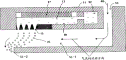
Fig. 5 is the schematic section according to an exemplary toner manufacturing equipment of the present invention.
Fig. 6 is the enlarged drawing of example of the drop deliverying unit of toner manufacturing equipment shown in Figure 5.
The backplan that Fig. 7 is a drop deliverying unit shown in Figure 6 when the bottom surface is seen.
Fig. 8 is the amplification sectional view of the drop discharge section of drop deliverying unit, and wherein Reference numeral 16A represents deformable zone.
Fig. 9 A is the explanatory schematic section of method for producing toner and toner with the exemplary shape of the exhaust opening of uniform efflux velocity discharge, and wherein phantom line segments A represents the center of discharge structure body, and arrow B is represented the direction that drop is discharged.
Fig. 9 B is the explanatory schematic section of method for producing toner and toner with the exemplary shape of the exhaust opening of uniform efflux velocity discharge, and wherein phantom line segments A represents the center of discharge structure body, and arrow B is represented the direction that drop is discharged.
Fig. 9 C is the explanatory schematic section of method for producing toner and toner with the exemplary shape of the exhaust opening of uniform efflux velocity discharge, and wherein arrow B is represented the direction that drop is discharged.
Figure 10 is the amplification sectional view of an exemplary conventional drop discharge section.
Figure 11 is the schematic section that is provided with the example of a plurality of drop deliverying units.
Figure 12 A is the explanatory sectional view that drop passes through the mechanism of drop deliverying unit discharge.
Figure 12 B is the explanatory sectional view that drop passes through the mechanism of drop deliverying unit discharge.
Figure 13 is the figure that is used to illustrate the reference of fundamental vibration mould institute.
Figure 14 is the figure that is used to illustrate the reference of secondary vibration mould institute.
Figure 15 is the figure that is used to illustrate the reference of three mode of vibration institutes.
Figure 16 is the explanatory diagram with discharge structure body (film or nozzle plate) of convex center part.
Figure 17 is the sectional bottom-view that is used for illustrating the discharge structure body cone angle that embodiment 1 to 3 is used.
Figure 18 A is the explanatory sectional view of standing wave, the speed under the situation that its end that shows the liquid chamber that produces liquid column resonance is stiff end and N=1 or the variation of pressure.
Figure 18 B is the explanatory sectional view of standing wave, the speed under the situation that its two ends that show the liquid chamber that produces liquid column resonance are stiff end and N=2 or the variation of pressure.
Figure 18 C is the explanatory sectional view of standing wave, the speed under the situation that its two ends that show the liquid chamber that produces liquid column resonance are open end and N=2 or the variation of pressure.
Figure 18 D is the explanatory sectional view of standing wave, the speed under the situation that its end that shows the liquid chamber that produces liquid column resonance is stiff end and N=3 or the variation of pressure.
Figure 18 E is the explanatory sectional view of standing wave, the speed under the situation that its two ends that show the liquid chamber that produces liquid column resonance are stiff end and N=4 or the variation of pressure.
Figure 18 F is the explanatory sectional view of standing wave, the speed under the situation that its two ends that show the liquid chamber that produces liquid column resonance are open end and N=4 or the variation of pressure.
Figure 18 G is the explanatory sectional view of standing wave, the speed under the situation that its two ends that show the liquid chamber that produces liquid column resonance are open end and N=5 or the variation of pressure.
Figure 19 schematically shows the cross section and the bottom surface of the discharge structure body that is used for embodiment 4 to 6.
Figure 20 shows an example of delivery air direction.
Figure 21 shows another example of delivery air direction.
Figure 22 shows the exemplary diagram that the solubleness of method for producing toner and toner in method for producing toner and toner liquid depends on temperature, and wherein A represents ageing, and B represents to filter, and C represents that drop forms, and each arrow is represented the more direction of polycomponent dissolving.
Figure 23 A shows the exemplary status that method for producing toner and toner liquid is discharged from exhaust opening.
Figure 23 B is the enlarged image of the dotted line region surrounded among Figure 23 A.
Embodiment
(making fine grain equipment of resin and method)
The present invention is used to make the fine grain equipment of resin and comprises that at least drop forms the unit and particle forms the unit; And if desired, further comprise other unit.
The present invention is used to make the fine grain method of resin and comprises that at least drop forms step and particle forms step; And if desired, further comprise other step.
The resin thin particle contains resin at least; And if desired, further contain other component.
Then will describe the present invention in detail and be used to make the fine grain method and apparatus of resin, be that toner-particle is an example with the resin thin particle.
The equipment that the present invention makes toner comprises that drop forms the unit and particle forms the unit; And if desired, further comprise other unit, method for producing toner and toner liquid filter element for example.
The method that the present invention makes toner comprises that drop forms step and particle forms step; And if desired, further be included in drop and form step other step before, for example method for producing toner and toner liquid preparation process, aging step and filtration step.The present invention is used to make the suitable equipment enforcement by above-mentioned manufacturing toner of method of toner.
Then, will make the equipment of toner, similarly describe the method for manufacturing toner of the present invention in detail together with the present invention.
<drop forms step and unit 〉
It is to discharge method for producing toner and toner liquid with uniform efflux velocity from a plurality of exhaust openings (some exhaust openings wherein have configurations differing from one) that drop forms step, thereby forms the step of drop, and this step forms unit enforcement by drop.
Drop forms the unit and does not limit especially, and can suitably select according to intended purposes, as long as it can discharge method for producing toner and toner liquid from a plurality of exhaust openings (some exhaust openings wherein have configurations differing from one) with uniform efflux velocity, thereby form drop.Drop forms the unit and preferably has liquid chamber and drop discharge section.
The type that drop forms the unit does not limit especially, can form drop as long as drop forms the unit, and can suitably select according to intended purposes.The example comprises that film oscillating mode drop forms the unit and liquid column resonance type drop forms the unit.
" film oscillating mode "
When following discharge structure body with a plurality of exhaust openings is film, film oscillating mode drop form the unit be configured to following vibration machine to film apply vibration with method for producing toner and toner liquid as the unit of drop from the exhaust opening discharge.
-liquid chamber-
Liquid chamber is arranged in the method for producing toner and toner flow channel, and stores following method for producing toner and toner.
The shape of liquid chamber does not limit especially, and can suitably select according to intended purposes.For example: liquid chamber has, for example, and cylindrical shape, the shape that the angle is arranged and coniform shape.
The structure of liquid chamber does not limit especially, and can suitably select according to intended purposes.Liquid chamber has, for example, and the single layer structure of forming by container, and bilayer or the stepped construction formed by container body and top layer.
The material of container can be identical or different with the material on the top layer that contacts method for producing toner and toner.
The material on the top layer of contact method for producing toner and toner does not limit especially, and can suitably select according to intended purposes.The example comprises metal, pottery, plastics and silicones (silicone).Wherein, preferably be insoluble to the material that method for producing toner and toner liquid does not make method for producing toner and toner liquid deterioration yet.
The size of liquid chamber does not limit especially, and can suitably select according to intended purposes.
-drop discharge section-
The drop discharge section comprises the discharge structure body that contains a plurality of exhaust openings (some exhaust openings wherein have difformity each other) at least, and vibration machine; And if desired, further comprise other parts.The drop discharge section applies with vibration machine and vibrates the discharge structure body, discharges thereby with uniform efflux velocity method for producing toner and toner is had difform exhaust opening as drop each other from some of them.
The drop discharge section does not limit especially, and can suitably select according to intended purposes.It is preferably by utilizing resonance effect will be included in the part that liquid in the liquid chamber (can be described as " reservoir ") forms drop.In this case, when the resonant frequency of the resonant frequency of liquid chamber and method for producing toner and toner liquid was overlapping, method for producing toner and toner liquid can not desirably receive vibration.Therefore, the resonant frequency of the method for producing toner and toner liquid in the liquid chamber preferably resonant frequency than liquid chamber is low, obtains uniform efflux velocity because the pressure of the method for producing toner and toner liquid in the liquid chamber evenly increases during forming at drop.
--discharge structure body--
The discharge structure body comprises a plurality of exhaust openings that are set to discharge method for producing toner and toner liquid at least, and some exhaust openings wherein have different shapes each other; And if desired, further comprise other parts.
When drop formation unit was the film oscillating mode, from obtaining the viewpoint of expectation vibration, the discharge structure body was preferably film or plate.
The area that this discharge structure body is formed with the surface (that is, having the surface of the discharge structure body of exhaust opening opening) of exhaust opening does not limit especially, and can suitably select according to the oscillation intensity that vibration machine applies.Its area is preferably 1 square millimeter to 80 square millimeters, more preferably 3 square millimeters to 20 square millimeters.When its area during less than 1 square millimeter, as described below forming under the situation that forms the delivery air passage in the unit at particle, the total area of exhaust opening opening is little with respect to the total area of discharge structure body, reduces toner production efficiency potentially.And when its area surpassed 80 square millimeters, it is excessive that making apparatus becomes, and even when the delivery air passage is provided, also may be difficult to obtain to prevent the effect of droplet congregating.
And the material of discharge structure body does not limit especially, and can suitably select according to intended purposes.This discharge structure body is preferably sheet metal.
The thickness of discharge structure body does not limit especially, and can suitably select according to intended purposes.It is preferably 5 μ m-500 μ m.
The shape of discharge structure body does not limit especially, and can suitably select according to intended purposes.When drop formation unit was the film oscillating mode, from the viewpoint of even vibration, the discharge structure body was preferably circular.In the cross section on the thickness direction of discharge structure body, preferably, the core on surface of discharge structure body with exhaust opening is outstanding to form bossing on the direction of discharging at drop.This is can control the direction that drop is discharged (advancing) because such bossing is set, and can vibrate whole discharge structure body more equably more to be formed uniformly drop.
And when drop formation unit was the film oscillating mode, the discharge structure body preferably was arranged in deflection when applying vibration.The method of discharge structure body deflection is not limited especially, and can suitably select according to intended purposes.The example of this method comprises that the discharge structure body connects/be fixed on the method on the framework that is arranged at discharge structure body outermost via the bonding part.
The elastic modulus that is used for the parts of bonding part does not limit especially, and can suitably select according to intended purposes.Its elastic modulus is preferably 10
8Pa or higher because can both set up concentric even vibrational state in each exhaust opening, stably discharges drop thus to obtain the having toner that uniform particle size distributes.
The material that use has high elastic modulus is that as the favourable part that is used for the parts of bonding part the discharge structure physical efficiency is fixed in the outermost of this discharge structure body securely.Use this configuration, vibration is propagated in the discharge structure body effectively.It is especially preferred when being circular configuration (film) that this is configured in discharge structure body (film), because vibration is propagated therein effectively.
Above-mentioned elastic modulus can pass through, and for example, supercritical ultrasonics technology is measured.
The whole exposed surface of discharge structure body and framework and/or discharge structure body and vibration machine is preferably scolded liquid film or cement electrical isolation with what insulating material was made.
Be used to scold the material of liquid film or cement not limit especially,, and can suitably select according to intended purposes as long as it is an insulating material.The example comprises fluorine resin for example polytetrafluoroethylene (PTFE), tetrafluoroethylene-perfluoroalkyl vinyl ether copolymer (PFA), fluorinated ethylene propylene (FEP) and polyvinylidene fluoride; Epoxy resin is bisphenol-A and Bisphenol F for example; And SiO
2These can be used alone or in combination.And, the liquid film of scolding of suitable use has been described among the JP-A No.2010-107904, it comprises SiO
2Film with its on the compound that has perfluoroalkyl and have the alkyl that is connected by siloxane bond at its end.
--exhaust opening---
In the discharge structure body, be formed with a plurality of exhaust openings (each exhaust opening is also referred to as " nozzle " or " through hole ").In the described exhaust opening some have different shape (that is, exhaust opening comprises having difform exhaust opening each other) each other.
The quantity of exhaust opening does not limit especially, and can suitably select according to intended purposes.When drop formation unit was the film oscillating mode, the quantity of the exhaust opening that forms in a discharge structure body was preferably 2-3000.
The minimum interval (spacing) at exhaust opening center adjacent one another are does not limit especially, and can suitably select according to intended purposes.From discharging the viewpoint of single-size, the exhaust opening preferred arrangements is to make that their center is the rule interval.
The size (opening size) of exhaust opening opening (drop of exhaust opening is discharged the end of side) does not limit especially, and can suitably select according to the anticipated volume of for example respectively discharging drop.From having the viewpoint of the fine drop of particle diameter very uniformly by method for producing toner and toner liquid is formed from exhaust opening discharge (spraying) as drop, it is preferably 3 μ m to 30 μ m.Each is discharged the volume of drop and is determined by the size of exhaust opening opening basically.For example, solidify to have the particle diameter of about 6 μ m in order to make toner-particle, the opening size of exhaust opening is preferably 8 μ m to 12 μ m.
Notice that when exhaust opening was the exhaust opening of proper circle shape, its opening size was meant its diameter.When exhaust opening is an oval-shaped exhaust opening or when having (rule) polygon (as square, hexagon and octagon) shape, its opening size is meant its mean diameter.
In the discharge structure body, the mode that exhaust opening is arranged does not limit especially, and can suitably select according to intended purposes.When drop formation unit was the film oscillating mode, exhaust opening preferably was arranged on perpendicular to the central area on the surface of discharge structure body thickness direction (can be described as " central area of discharge structure body " hereinafter).
When the toner manufacturing equipment has at the following vibration machine around the discharge structure body, bee-line from the exhaust opening to the vibration machine does not limit especially, and can suitably select according to the area of for example discharge structure body with by the oscillation intensity that vibration machine applies.The vibration displacement that exhaust opening preferably is arranged on the discharge structure body is not 0 position.Be the exhaust opening place of 0 position at the vibration displacement that is arranged at the discharge structure body, method for producing toner and toner liquid can ooze out from it.
The shape of exhaust opening does not limit especially, and can suitably select according to intended purposes, as long as some in the described exhaust opening have different shapes each other, and method for producing toner and toner liquid can be discharged between each exhaust opening equably.
Preferably, the round-shaped or conical in shape that reduces gradually of the shape of the exhaust opening direction that to be its opening size discharge along drop (method for producing toner and toner liquid).When exhaust opening had conical in shape, exhaust opening preferably had according to position in the discharge structure body and different cone angles.When exhaust opening has when round-shaped, exhaust opening preferably has according to the position in the discharge structure body and different radius-of-curvature.By this way, have according to position in the discharge structure body and when different cone angles or radius-of-curvature, method for producing toner and toner can be discharged equably when exhaust opening.In other words, by along with the cone angle of the position change exhaust opening in structure or radius-of-curvature with according to the position adjustments pressure loss of exhaust opening in the discharge structure body, the efflux velocity at exhaust opening place can be controlled to even velocity and discharge method for producing toner and toner liquid from exhaust opening.This is preferred, because being distributed in of liquid efflux velocity becomes identically between each exhaust opening, toner-particle can form with high precision as a result.
Here, " cone angle " is meant: with respect to the vertical line (axle) of the surface with exhaust opening opening (that is) perpendicular to the surface of discharge structure body thickness direction, and formed angle between the side in the cross section of each exhaust opening on discharge structure body thickness direction.And " radius-of-curvature " is meant: on the thickness direction of discharge structure body, and the radius-of-curvature of the circle that the surface of discharge structure body thickness direction (that is, perpendicular to) is crooked from surface with exhaust opening opening.Cone angle or radius-of-curvature can be passed through usefulness, and for example, the confocal microscopy sem observation is measured.
Be used for forming the qualification especially of method of exhaust opening, and can suitably select according to intended purposes at the discharge structure body.The example comprises by electroforming handles the method for discharge structure body and the method by discharge process discharge structure body.And, be used to handle exhaust opening the method for its cone angle with expectation or radius-of-curvature is not limited especially, and can suitably select according to intended purposes.When adopting electroforming to handle the discharge structure body, the exhaust opening of formation can be handled by for example IGA method.When adopting discharge to handle the discharge structure body, the exhaust opening of formation can pass through, and for example, handles with the method for electrode control.
--vibration machine--
Vibration machine does not limit especially, as long as it can produce vibration, and can suitably select according to intended purposes.Vibration machine applies and vibrates the discharge structure body, thereby discharges method for producing toner and toner liquid in the exhaust opening of discharge structure body with the form of drop.
The instantiation of vibration machine comprises ultrasonic generator, and it produces mechanical vibration by piezoelectric effect or magnetostrictive effect.Among these, preferably can convert electricity those of mechanical vibration to, because they can produce the vibration of higher frequency effectively by piezoelectric effect.The example comprises piezoelectric element.
The material of piezoelectric element does not limit especially, and can suitably select according to intended purposes.The example comprises piezoelectric ceramics, for example lead zirconate titanate (PZT); Piezopolymer is polyvinylidene fluoride (PVDF) for example; And monocrystalline for example crystal, LiNbO
3, LiTaO
3And KNbO
3In these, from the viewpoint of control vibration, lead zirconate titanate (PZT) is preferred.
The position of vibration machine does not limit especially, as long as method for producing toner and toner liquid can vibrate effectively, and can suitably select according to intended purposes.When drop forms the unit and is the film oscillating mode, vibration machine preferably be arranged on the discharge structure body region that is formed with exhaust opening around, more preferably, vibration machine be arranged on ring-type the discharge structure body region that is formed with exhaust opening around.
The method that vibration machine is set around the discharge structure body region that is formed with exhaust opening does not limit especially, and can suitably select according to intended purposes.Example involving vibrations generator connects/is fixed on method on the discharge structure body via the bonding part.In this case, particularly preferably, vibration machine is arranged on ring-type around the zone that is formed with exhaust opening, and this zone is present in the discharge structure body and is not fixed within the zone (can be described as " deformable zone " hereinafter) on the framework that is arranged at discharge structure body outermost.
The formation of-drop-
Then will describe when drop formation unit is the film oscillating mode, form step, the mechanism that method for producing toner and toner liquid is periodically discharged as drop at drop.
When the discharge structure body was film, vibration machine produces and apply to vibrate had a plurality of discharge structure bodies (film) of facing the exhaust opening of liquid chamber, thereby periodically vibrates the discharge structure body.Use this configuration, a plurality of exhaust openings can be arranged in the big relatively area (1 millimeter of diameter or bigger), and drop can periodically be discharged from exhaust opening reliably.
When as the discharge structure body 16 of the simple circular film shown in Figure 12 A and the 12B at 12A place, its peripheral region fixedly the time, the fundamental vibration that takes place during vibration has node in this peripheral region.As shown in figure 13, discharge structure body 16 has wherein vibration displacement Δ L at core O place (promptly, exhaust opening place at the core that is positioned at the discharge structure body) maximum (Δ Lmax), and vibration displacement Δ L at the exhaust opening place of outermost (promptly, be positioned at the exhaust opening place of vibration machine side) cross sectional shape of minimum (Δ Lmin), and discharge structure body 16 periodically vibrates at vertical direction.Notice that the exhaust opening that is arranged in the position that obtains minimum vibration displacement (Δ Lmin) preferably is arranged on the zone of not colliding with vibration machine/adhering to from the drop of its discharge.
Note, had known high order mode of vibration secondary vibration mould as shown in figure 14 and three mode of vibration shown in Figure 15.In these moulds, one or more nodes are formed in the circular membrane with one heart, and the distortion axisymmetrically basically of this film.And the discharge structure body 16 that uses the heart therein partly to have bossing 12C (as shown in figure 16) can be controlled the moving direction of Oscillation Amplitude and drop to a certain extent.
Vibration displacement can be measured with LASER DOPPLER VIBROMETER.
When 16 vibrations of discharge structure body, acoustic pressure Pac is applied to and is present in the contiguous liquid of exhaust opening that forms in the circular membrane (discharge structure body).Acoustic pressure Pac is directly proportional with the vibration velocity Vm of discharge structure body.Acoustic pressure is known to be that reaction owing to the radiation impedance Zr of medium (method for producing toner and toner liquid) occurs, and is expressed as the product of the vibration velocity Vm of radiation impedance and discharge structure body, shown in following equation (1).
Pac(r,t)=Zr·Vm(r,t) (1)
The vibration velocity Vm of vibrational structure periodically changes (that is, being the function of time (t)) in time, and can form multiple cyclical variation (for example, sinusoidal waveform and square-wave waveform).And the vibration displacement on the direction of vibration changes (that is, vibration velocity Vm still is the function of position in the discharge structure body) according to the position in the vibrational structure body.As mentioned above, the vibration mode that is used for discharge structure body of the present invention is axisymmetric.Therefore, vibration mode is the function of radial coordinate (r) basically.
Applying when vibration, be present in the method for producing toner and toner liquid reception Fn in each exhaust opening, Fn is that (r is t) with the product of the cross-sectional area Sn of the exhaust opening of method for producing toner and toner liquid supply side for acoustic pressure Pac.Power Fn is represented by following equation (2).
Fn=Pac (r, t) Sn... equation (2)
Notice that acoustic pressure Pac is not constant on the whole cross section of the exhaust opening of method for producing toner and toner liquid supply side, but under the cross section was considered to enough little situation, power Fn was approximately the function of the coordinate of radius (r).And character n represents from the exhaust opening quantity of discharge structure body center; That is n exhaust opening.Be clear that from above equation (2) Sn is big more, power Fn is big more, and by regulating Sn, power Fn can be uniform.In fact, power Fn stands local losses and passage loss, and by deducting the efflux velocity of making a concerted effort to become method for producing toner and toner liquid that they obtain.Yet, consider these pressure losses, might regulate efflux velocity.
The efflux velocity of method for producing toner and toner liquid does not limit especially, and can suitably select according to intended purposes.It is preferably 8m/s to 20m/s, and more preferably 12m/s is to 16m/s.When its efflux velocity is lower than 8m/s, may assembles each other from the drop that exhaust opening is discharged, and when its efflux velocity surpasses 20m/s, may form accompaniment (satellite), and method for producing toner and toner liquid may ooze out from exhaust opening.Here, accompaniment is that diameter is 1/2 a drop of the main liquid-drop diameter that forms.
Efflux velocity preferably is uniform in all exhaust openings.Therefore, the ratio of the efflux velocity at the exhaust opening place of the maximum vibration displacement L (Δ Lmax) of the efflux velocity at the exhaust opening place of the minimum vibration displacement L (Δ Lmin) of acquisition discharge structure body and acquisition discharge structure body (promptly, obtain the efflux velocity at exhaust opening place of efflux velocity/acquisition Δ Lmax at the exhaust opening place of Δ Lmin) be preferably 0.5 to 1.0, more preferably 0.8 to 1.0.
The method of measuring efflux velocity does not limit especially, and can suitably select according to intended purposes.For example, the state that method for producing toner and toner liquid is discharged from exhaust opening can be by following affirmation: the method for producing toner and toner dispersion liquid that illuminates discharge with LED, with the method for producing toner and toner dispersion liquid of being arranged to discharge in the face of the CCD camera of LED via the method for producing toner and toner dispersion liquid of discharging, and the vibration frequency of the driving frequency that makes LED and drop discharge section (makes the time that the vibration of vibration machine produces and applies voltage consistent to carry out the luminous time to LED) synchronously.
Figure 23 A shows the state that the method for producing toner and toner dispersion liquid is discharged from unshowned exhaust opening, and Figure 23 B is the enlarged image of the dotted line region surrounded among Figure 23 A.The fluid column of the method for producing toner and toner dispersion liquid of discharging from exhaust opening by applying certain vibration at regular intervals constriction to form constriction p (can be described as " fluid column constriction " hereinafter).The first end parts of fluid column is separated into a certain amount of drop, makes the toner-particle (Figure 23 A) with certain particle diameter thus continuously.Efflux velocity (m/s) can use the constriction and the vibration frequency of discharging fluid column generally to be calculated by following equation: efflux velocity=constriction wavelength (μ m)/vibration frequency (kHz).Here, " constriction wavelength " is meant the maximum length from unshowned exhaust opening opening to the fluid column constriction p (that is the fluid column constriction p of the most close exhaust opening opening) that occurs for the first time the fluid column of the method for producing toner and toner dispersion liquid of being discharged by the exhaust opening opening.
At method for producing toner and toner liquid periodically after the exhaust opening end of discharging side is discharged to the gas phase of exhaust opening outside, it is owing to the surface tension difference between gas phase and the exhaust opening (liquid phase) becomes sphere, and method for producing toner and toner liquid is periodically discharged with the form of drop thus.
The method for producing toner and toner liquid that can make that is applied to the discharge structure body does not limit especially with the frequency of the vibration of drop form discharge, and can suitably select according to intended purposes.It typically is 20kHz to 2.0MHz, be preferably 50kHz to 500kHz.When vibration frequency is 20kHz or when higher, the excitation by method for producing toner and toner liquid has promoted the dispersiveness of the fine grained (for example, pigment and/or Wax particles) that contains in the method for producing toner and toner liquid.
Acoustic pressure does not limit especially, and can suitably select according to intended purposes.When acoustic pressure is 10kPa or when higher, preferably, further promote fine grain dispersiveness.Owing to when method for producing toner and toner liquid has 20mPas or lower viscosity and 20mN/m to the surface tension of 75mN/m, produce accompaniment similarly, so acoustic pressure is necessary for 500kPa or lower.Especially, acoustic pressure is preferably 100kPa or lower.
" liquid column resonance type "
When the following discharge structure body with a plurality of exhaust openings is that it is with lower unit that the drop of liquid column resonance type forms the unit when limiting wall of liquid chamber.Specifically, it is to form the pressure standing wave by apply the caused liquid column resonance of vibration with the method for producing toner and toner liquid of following vibration machine in liquid chamber that liquid column resonance type drop forms configuration of cells, thereby the drop of method for producing toner and toner liquid is discharged from being formed on corresponding to the exhaust opening the zone of pressure standing wave antinode.
" corresponding to the zone of pressure standing wave antinode " is big, the pressure variation zone greatly of amplitude by the pressure standing wave of liquid column resonance generation, and obtains discharging the enough big pressure variation of drop.Zone corresponding to pressure standing wave antinode does not limit especially, and can suitably select according to intended purposes.It is preferably from the amplitude of pressure standing wave become maximum position (node of speed standing wave) to the amplitude of pressure standing wave become minimum position ± 1/3 wavelength coverage in, more preferably ± 1/4 zone in the wavelength coverage.
In the time of in exhaust opening is formed on corresponding to the zone of pressure standing wave antinode, drop can be discharged from exhaust opening basically equably.In addition, drop can be discharged effectively, relates to less exhaust opening and stops up, and this is preferred.
-liquid chamber-
Form at liquid column resonance type drop under the situation of unit, the shape of liquid chamber, structure and size do not limit especially, and can suitably select according to intended purposes.For example, liquid chamber can have identical shape, structure and the size of liquid chamber that forms the unit with film oscillating mode drop.
The material of liquid chamber can be the liquid chamber identical materials that for example forms the unit with film oscillating mode drop.
When drop formation unit was the liquid column resonance type, liquid chamber (producing the liquid chamber of liquid column resonance) was to use the vibration that applies by vibration machine to form the liquid chamber of pressure standing wave according to the principle of following liquid column resonance phenomenon.Liquid chamber has the exhaust opening that forms in the zone corresponding to pressure standing wave antinode, but also have the intercommunicating pore that is used to supply with method for producing toner and toner liquid (the liquid chamber that produces liquid column resonance vertically on the place, end).If desired, liquid chamber the liquid chamber that produces liquid column resonance vertically at least a portion place of one or both ends, have reflective wall (its perpendicular to the liquid chamber that produces liquid column resonance vertically).
Here, " reflective wall " is meant by enough hard made walls of parts (for example aluminium or stainless metal parts, perhaps silicone parts) of sound wave with reflection liquid.
As shown in Figure 2 the liquid chamber that produces liquid column resonance vertically on the wall at place, two ends between length L do not limit especially, and can suitably select according to intended purposes.It is preferably determined according to the principle of following liquid column resonance phenomenon.And the width W of the liquid chamber of generation liquid column resonance shown in Figure 3 does not limit especially, and can suitably select according to intended purposes.Width W is preferably less than 1/2 of the length L of the liquid chamber that produces liquid column resonance, in order to avoid make liquid column resonance have unnecessary frequency.
The quantity of liquid chamber does not limit especially, and can suitably select according to intended purposes.When drop formed the unit and is the liquid column resonance type, from realizing the viewpoint of the favourable balance between operability and the throughput rate, the quantity of liquid chamber was preferably 100 to 2,000, and more preferably 100 to 1,000, be preferably 100 to 400 especially.Note the direction that horizontally extending from right to left arrow express liquid flows to material container 6 from ebullator 100 in Fig. 3.
-drop discharge section-
The drop discharge section comprises discharge structure body and vibration machine at least; And if desired, further comprise other parts.In the drop discharge section, apply from vibration machine and to vibrate method for producing toner and toner liquid, thereby discharge the drop of method for producing toner and toner liquid with uniform efflux velocity from exhaust opening (some exhaust openings wherein have difformity each other).
The drop discharge section does not limit especially, and can suitably select according to intended purposes.Preferably, it utilizes resonance effect that the liquid that exists in the liquid chamber is formed drop.In this case, when the resonant frequency of the resonant frequency of liquid chamber and method for producing toner and toner liquid was overlapping, method for producing toner and toner liquid can not desirably receive vibration.Therefore, the resonant frequency of the method for producing toner and toner liquid in the liquid chamber preferably less than the resonant frequency of liquid chamber, because the pressure of the method for producing toner and toner liquid in the liquid chamber evenly increases, obtains uniform efflux velocity during forming at drop.
--discharge structure body--
The discharge structure body comprises a plurality of exhaust openings that are set to discharge method for producing toner and toner liquid at least, and some exhaust openings wherein have different shapes each other; And if desired, further comprise other parts.
When drop formation unit was the liquid column resonance type, the discharge structure body was a wall that limits the liquid chamber that produces liquid column resonance.
(that is, the surface with exhaust opening opening of discharge structure body) area, thickness and shape do not limit especially, and can suitably select according to the oscillation intensity that applies by vibration machine to be formed with the surface of the discharge structure body of exhaust opening.For example, they be with the film oscillating mode in area identical, thickness and the shape described.
And the material of discharge structure body does not limit especially, and can suitably select according to intended purposes.For example, its material be with the film oscillating mode in discharge structure body identical materials.For principle according to following liquid column resonance, form the pressure standing wave in the method for producing toner and toner liquid in the liquid chamber that produces liquid column resonance, thereby the drop of method for producing toner and toner liquid is discharged from being arranged on corresponding to the exhaust opening the zone of pressure standing wave antinode, the discharge structure body preferably joins the framework of being made by following material to, and described material has high rigidity makes this material not influence the resonant frequency of method for producing toner and toner liquid.The example of described material comprises metal, pottery and silicones.
The whole exposed surface of discharge structure body can have following insulation and scold liquid film.
Scold liquid film not limit especially, and can suitably select according to intended purposes.For example, scold liquid film can with the film oscillating mode in identical.
--exhaust opening---
In the discharge structure body, form a plurality of exhaust openings.In the described exhaust opening some have different shapes each other.
The quantity of exhaust opening does not limit especially, and can suitably select according to intended purposes.When drop formed the unit and is the liquid column resonance type, the quantity of exhaust opening can produce one of the liquid chamber of liquid column resonance for each, but from the viewpoint of improving throughput rate two or more exhaust openings is set preferably.Each quantity of exhaust opening that produces the liquid chamber of liquid column resonance is preferably 2 to 100, and more preferably 4 to 60, be preferably 4 to 20 especially.When each quantity of exhaust opening that produces the liquid chamber of liquid column resonance surpasses 100, the voltage that is applied to vibration machine must be made as high, forming the drop of the method for producing toner and toner liquid of expectation from 100 exhaust openings, so the performance potentially unstable of vibration machine.When each quantity of exhaust opening that produces the liquid chamber of liquid column resonance is 4 to 20, standing wave be stabilization to keep high productivity.
And, when drop formation unit is the liquid column resonance type, does not limit especially corresponding to exhaust opening quantity that the zone of pressure standing wave antinode is provided with at least one, and can suitably select according to intended purposes.This exhaust opening quantity is preferably 1 to 20, and more preferably 4 to 15, be preferably 4 to 10 especially.Exhaust opening quantity is many more, and throughput rate is high more.When exhaust opening quantity surpassed 20, exhaust opening was arranged overstockedly.As a result, discharge drop and assemble the formation coarse particle each other, the potential image quality that influences unfriendly.
The size (opening size) of the minimum interval (spacing) at exhaust opening center located adjacent one another or exhaust opening opening (exhaust opening is discharged the end of side at drop) does not limit especially, and can be according to for example, and each is discharged the anticipated volume of drop and suitably selects.Spacing and opening size are preferably identical with spacing and opening size in the film oscillating mode.
When drop formation unit is the liquid column resonance type, the position of exhaust opening in the discharge structure body do not limit especially, as long as they are arranged in the zone corresponding to pressure standing wave antinode, and can according to the liquid chamber that for example produces liquid column resonance vertically on two ends between length L and the width W that produces the liquid chamber of liquid column resonance suitably select.
Represent as L above generation liquid column resonance liquid chamber vertically on two ends between length, and Le represent to produce liquid column resonance liquid chamber an end and between the exhaust opening center of close this end apart from the time, the ratio of Le/L does not limit especially, and can suitably select according to intended purposes.It is preferably greater than 0.6.
The shape of exhaust opening does not limit especially, and can suitably select according to intended purposes, as long as some in the described exhaust opening have different shapes each other and can discharge method for producing toner and toner liquid equably from this exhaust opening.Preferably, exhaust opening have separately with the film oscillating mode in identical shape.
--vibration machine--
Vibration machine does not limit especially, as long as it can produce vibration, and can suitably select according to intended purposes.For example, vibration machine can with the film oscillating mode in identical.
When drop formation unit was the liquid column resonance type, the position of vibration machine did not limit especially, and can suitably select according to intended purposes.Vibration machine be preferably formed in the liquid chamber that produces liquid column resonance with the lower wall place, this wall to the wall that is formed with exhaust opening (that is, produce liquid column resonance liquid chamber vertically on the surface).
And vibration machine preferably is attached on the elastic plate.Elastic plate is preferably formed the part into the wall of liquid column resonance chamber, makes vibration machine not contact with liquid.
And each vibration machine preferably is arranged in the liquid chamber of a generation liquid column resonance, makes them to control individually.And for example block piezoelectric element of each vibration machine preferably produces the liquid chamber setting of liquid column resonance via elastic plate corresponding to each, because can control the liquid chamber that produces liquid column resonance individually.
The formation of-drop-
The mechanism that method for producing toner and toner liquid is periodically discharged as drop then will be described when using liquid column resonance type drop to form the unit in drop formation step.
When c represents to produce the velocity of sound of method for producing toner and toner liquid in the liquid chamber of liquid column resonance, f represents to be applied to from vibration machine the driving frequency of method for producing toner and toner liquid (medium), when λ represented to produce the wavelength of resonance of liquid, these c, f and λ satisfied following equation (3).
λ=c/f... equation (3)
Fig. 2 is the sectional view of an example of drop discharge section.In the liquid chamber 12 of generation liquid column resonance shown in Figure 2, L represents to fix the length of distolateral frame ends 54 to the other end 55 of public liquid feeding passage 52 sides from it, h1 represents the height (the about 80 μ m of h1=) of the frame ends of public liquid feeding passage 52 sides, and h2 represents the height (the about 40 μ m of h2=) of intercommunicating pore.
The end of supposing public liquid feeding passage 52 sides is equivalent to the stiff end in the closed state; That is, all be considered under the situation of stiff end two ends, resonance forms when length L equals the even multiple of 1/4 wavelength X most effectively.That is, length L is represented by following equation (4).
L=(N/4) λ ... equation (4)
Wherein N represents even number.
Notice that " being equivalent to stiff end " is the situation that the end can be considered to not have pressure escape position, for example in the end, the height of reflective wall is the above situation of twice of height that is used to supply with the intercommunicating pore of method for producing toner and toner liquid; Perhaps in the end, the area of reflective wall is the above situation of twice of area that is used to supply with the intercommunicating pore of method for producing toner and toner liquid.
When two ends are the open end; That is, when two ends are all open fully, and when two ends were equivalent to the open end, above-mentioned equation (4) was set up.
Similarly, when an end is equivalent to the open end that pressure is escaped, and during other end sealing (stiff end); That is, at one end be fix or an end be that resonance forms when length L equals the odd multiple of 1/4 wavelength X most effectively under the open situation.That is to say that length L is above equation (4) expression of odd number by N wherein.Notice that when two ends were the open end, L was the even multiple of 1/4 wavelength X.When an end was stiff end, L was the odd multiple of 1/4 wavelength X.
Based on above equation (3) and (4), calculate the most effective driving frequency f by following equation (5):
F=N * c/ (4L) ... equation (5)
Wherein L represents to produce the length of liquid chamber on it is vertical of liquid column resonance, and c represents the velocity of sound of method for producing toner and toner liquid, and N is an integer.
Therefore, in method for preparing toner of the present invention, the vibration that preferably will have the frequency f that is obtained by above equation (5) is applied to method for producing toner and toner liquid.In fact, liquid has the viscosity that makes the resonance decay, and therefore vibration is not unlimited (observing the Q factor) of amplifying.Yet, shown in following equation (6) and (7), though with the approaching frequency place of the most effective driving frequency f that obtains by equation (5), also produced resonance.
Figure 18 A-G shows the shape (resonant mode) of standing wave, and it shows N is 1,2,3,4 or 5 o'clock the speed and the variation of pressure.
In fact, standing wave is wave of compression (compressional wave); Yet it is usually expressed as shown in Figure 18 A-G.In Figure 18 A-G, solid line is that speed standing wave (distribution of speed) and dotted line are pressure standing wave (pressure distribution).
For example, from Figure 18 A (end is fixed and the situation of N=1) as can be seen, the amplitude of velocity distribution becomes zero and become maximum in the open end at blind end.
Represent to produce at L liquid column resonance liquid chamber vertically on two ends between length, and λ represents to produce under the situation of wavelength of liquid resonance, standing wave is to produce most effectively in 1 to 5 o'clock in Integer N.Further, the pattern of standing wave (pattern) is sealing or that open and different according to each end, has therefore also described different patterns.As described below, the condition of end is determined by the opening condition of supplying according to the state and the liquid of exhaust opening opening.
Notice that in acoustics, the open end is that medium (liquid) translational speed in the vertical is zero, and the end of pressure maximum.Simultaneously, the blind end translational speed that is defined as medium becomes zero end.Such blind end is considered to sclerine and at this blind end generation wave reflection with regard to acoustics.When each holds ideally complete closed or when open, because the stack of ripple, the standing wave that is caused by liquid column resonance produces with the form shown in Figure 18 A-G.Yet the pattern of standing wave changes according to the quantity and the position of exhaust opening.Resonant frequency appears at the position of the offset that obtains with above equation, but can set up stable condition of discharging by suitably regulating driving frequency.
For example, under the following conditions, the most effective resonant frequency that is calculated by above equation (4) is 324kHz: the velocity of sound c of liquid is 1200m/s, the length L that produces the liquid chamber of liquid column resonance is 1.85mm, wall is present in both sides, and resonant mode is the pattern that is equivalent to the N=2 under the situation that two ends are stiff end fully.
As another example, under the following conditions, the most effective resonant frequency that is calculated by above equation (4) is 648kHz: the velocity of sound c of liquid is 1200m/s, the length L that produces the liquid chamber of liquid column resonance is 1.85mm, wall is present in both sides, and resonant mode is the pattern that is equivalent to the N=4 under the situation that two ends are stiff end.Even use the liquid chamber of generation liquid column resonance, also can utilize high subresonance with identical configuration.
Further, the quantity of exhaust opening 15, its layout and its cross sectional shape also can be the factors of determining driving frequency, and driving frequency can suitably be determined according to them.
For example, when the quantity of exhaust opening 15 increased, the restriction of the stiff end of the chamber 12 of generation liquid column resonance was loosened gradually.As a result, the resonant stationary wave resonant stationary wave much at one that obtains with the open end occurred, and driving frequency increases.And restrictive condition begins to loosen from being present in apart from the position of the nearest exhaust opening 15 of public liquid feeding passage 52.And when the volume of exhaust opening changed according to the thickness of discharge structure body, the actual standing wave that obtains had the short wavelength, and than the driving frequency height that adopts.Further, when under the driving frequency of determining thus when vibration machine applies voltage, vibration machine 17 deforms, and produces resonant stationary wave most effectively under this driving frequency.And, even with the approaching frequency of the driving frequency that produces resonant stationary wave most effectively under, also produced the liquid column resonance standing wave.That is to say, use the drive waveforms mainly contain the driving frequency f in the scope of determining based on two length L and Le by following formula (6) and (7), make vibration machine realize vibration, thereby the excitation liquid column resonance is with from exhaust opening discharge drop.Here, L represents to produce the length between the liquid chamber two ends in the vertical of liquid column resonance, and Le represents the distance between exhaust opening 15 centers of the end 55 of public liquid feeding channel side and the most close end 55.
N * c/ (4L)≤f≤N * c/ (4Le) ... expression formula (6)
N * c/ (4L)≤f≤(N+1) * c/ (4Le) ... expression formula (7)
Here L represents to produce the liquid chamber length in the vertical of liquid column resonance, the end of Le express liquid feeding channel side and the distance between the exhaust opening of close this end, and c represents the velocity of sound of method for producing toner and toner liquid, N is an integer.
Use the principle of above-mentioned liquid column resonance phenomenon, in the chamber 12 of generation liquid column resonance shown in Figure 2, form liquid column resonance pressure standing wave, and drop is discharged from the exhaust opening 15 of the part that is arranged in the chamber 12 that produces liquid column resonance continuously.Notice that exhaust opening 15 preferably is arranged in standing wave pressure and becomes maximum position, improve, and realize using low voltage drive because discharge efficient.
Be described in the state of the liquid column resonance phenomenon that produces in the chamber of generation liquid column resonance of drop discharge section below with reference to Fig. 4 A-E.
Note, in Fig. 4 A-E, the solid line of writing in producing the liquid chamber of liquid column resonance represents that the velocity distribution of drawing and obtaining by the speed that each measuring position is measured, described each measuring position are selections at random the position in the scope of the fixing distolateral end to public liquid feeding channel side of the liquid chamber that produces liquid column resonance.And, be defined as+(just) from the direction of public liquid feeding channel side, and opposite direction is defined as-(bearing) towards the liquid chamber that produces liquid column resonance.
In addition, in Fig. 4 A-E, produce the dotted line of writing in the liquid chamber of liquid column resonance and represent that the pressure distribution of drawing and obtaining by the pressure that each measuring position is measured, described each measuring position are selections at random the position in the scope of the fixing distolateral end to public liquid feeding channel side of the liquid chamber that produces liquid column resonance.And, be defined as+(just) with respect to atmospheric normal pressure, and be defined as-(bearing) with respect to atmospheric negative pressure.
When pressure is normal pressure, exert pressure downwards in the accompanying drawings; And when pressure is negative pressure, upwards exert pressure in the accompanying drawings.
In addition, in Fig. 4 A-E, as mentioned above, the liquid chamber that produces liquid column resonance is open in public liquid feeding passage 52 sides.Yet, owing to be preferably as the height (h1 shown in Figure 2) of the framework of stiff end more than about twice of the height (h2 shown in Figure 2) that makes the intercommunicating pore that public liquid feeding passage 52 is communicated with the liquid chamber 12 that produces liquid column resonance, demonstrate at the two ends of the liquid chamber 12 of generation liquid column resonance all be basically velocity distribution under the approximate condition of stiff end and pressure distribution over time.
Fig. 4 A shows pressure waveform and the velocity wave form in the liquid chamber 12 of the generation liquid column resonance when discharging drop.And shown in Fig. 4 B, when liquid was fed into the liquid chamber 12 that produces liquid column resonance after just discharging drop, the pressure that is applied to meniscus increased once more.Shown in Fig. 4 A and 4B, pressure is maximum in the zone that is provided with exhaust opening 15 of the liquid chamber 12 that produces liquid column resonance.Subsequently, shown in Fig. 4 C, change, discharge drop 23 thus in the contiguous normal pressure reduction of locating of exhaust opening 15 and to negative pressure.
Further, shown in Fig. 4 D, the pressure at exhaust opening 15 contiguous places becomes minimum.Light from this time, method for producing toner and toner liquid 12 begins to fill the liquid chamber 12 that produces liquid column resonance.Subsequently, shown in Fig. 4 E, the negative pressure at exhaust opening 15 contiguous places diminishes and changes to normal pressure.At this time point, the filling of method for producing toner and toner liquid 12 stops.Then, shown in Fig. 4 A, the normal pressure of the drop discharging area in the liquid chamber 12 that produces liquid column resonance becomes maximum, and drop 23 is discharged from exhaust opening 15.By this way, in producing the liquid chamber of liquid column resonance, the high-frequency drive by vibration machine produces the standing wave that is caused by liquid column resonance.And because the pressure that exhaust opening 15 is arranged in corresponding to the antinode of the standing wave that produces by liquid column resonance becomes in the maximum zone, drop 23 is discharged from exhaust opening 15 continuously according to the circulation of antinode.
Notice that the efflux velocity in liquid column resonance type situation is preferably similar with efflux velocity in film oscillating mode situation.Efflux velocity in liquid column resonance type situation also can be by measuring with the identical method in film oscillating mode situation.
Method for producing toner and toner liquid does not limit especially in the temperature that drop forms step, and can suitably select according to intended purposes.It is preferably-50 ℃ to 70 ℃, more preferably 0 ℃ to 60 ℃.Preferably make method for producing toner and toner liquid be higher than the temperature of method for producing toner and toner liquid, particularly preferably, make the former temperature than at least 1 ℃ of latter's temperature height at following filtration step in the temperature that drop forms step.When regulating the temperature of method for producing toner and toner liquid in each step, the component that is dissolved in the method for producing toner and toner liquid with state of saturation does not precipitate after filtration, to prevent to form coarse particle.This is because the component that is dispersed in the method for producing toner and toner liquid is tended to dissolve manyly in drop formation step, makes method for producing toner and toner (toner component) be difficult to precipitation.
<drop forms the step before the step 〉
In the present invention, liquid preparation/supplying step such as method for producing toner and toner liquid preparation process, aging step and filtration step form step step enforcement before as drop.
" method for producing toner and toner liquid preparation process "
Method for producing toner and toner liquid preparation process is dissolving or disperse the step of method for producing toner and toner with preparation method for producing toner and toner liquid in organic solvent.
Prepare method for producing toner and toner liquid by disperseing in organic solvent or dissolving method for producing toner and toner, described method for producing toner and toner contains resin and colorant at least; And if desired, further contain other component such as magnetic material, wax and fluidity improver.
Method for producing toner and toner also can be the method for producing toner and toner that is used to form conventional electrofax tinter.Specifically, following method for producing toner and toner is discharged as fine drop, carry out drying and curing then, thereby make the toner-particle of expection, described method for producing toner and toner is by comprising the preparation of following process: with resin dissolves in any kind of various organic solvents, the toner that is scattered here and there therein, and disperse or dissolve release agent therein.And, following liquid is discharged as fine drop, carry out drying and curing then, thereby make the toner-particle of expection, described liquid is by comprising the preparation of following process: the above material of melt kneading is with preparation melt kneading product, and this melt kneading product dissolved or is dispersed in any kind of various organic solvents.
The viscosity of method for producing toner and toner liquid does not limit especially, and can suitably select according to intended purposes.It is preferably 0.5mPas to 15mPas, and more preferably 0.5mPas is to 1.5mPas.When viscosity surpassed 15mPas, method for producing toner and toner liquid sometimes can not be discharged owing to the high viscosity resistance.
The viscosity of method for producing toner and toner liquid can be by for example cone-plate type rotary viscosity measuring.
-resin-
Resin does not limit especially, and can suitably select according to intended purposes.The example of resin comprises by for example, the vinylite that styrene monomer, acryl monomer and methacryl monomer are made, vibrin; polyol resin, phenolics, organic siliconresin; urethane resin; polyamide, furane resin, epoxy resin; xylene resin; terpene resin, coumarone-indene resin, polycarbonate resin and petroleum resin.These can be used alone or in combination.
-colorant-
Colorant does not limit especially and can suitably select according to intended purposes.The example of colorant comprises carbon black, aniline black byestuffs, iron black, naphthol yellow S, Hansa yellow (10G, 5G and G), cadmium yellow, iron oxide yellow, sil, lead and yellow-collation, titan yellow, the polyazo Huang, oil yellow, Hansa yellow (GR, A, RN and R), pigment yellow L, benzidine yellow (G and GR), permanent yellow (NCG), Fu Erkan fast yellow (5G, R), tartrazine lake, quinoline yellow lake, the yellow BGL of anthracene, the iso-dihydro-indole Huang, colcother, the red lead, red lead, cadmium red, cadmium mercury is red, antimony red, permanent bordeaux 4R, para red, red as fire, p-chloro-o-nitroaniline red, lithol that fast scarlet G, bright fast scarlet, bright fuchsin BS, permanent bordeaux (F2R, F4R, FRL, FRLL and F4RH), fast scarlet VD, the strong rubine B of Fu Erkan, brilliant scarlet G G, lithol that rubine GX, permanent bordeaux F5R, bright fuchsin 6B, pigment scarlet 3B, the red 5B of wine, the toluidine chestnut, consolidate the red F2K of wine forever, the red BL of dust Leo wine, the red 10B of wine, light BON chestnut, middle BON chestnut, eosine lake, rhodamine color lake B, rhodamine color lake Y, alizarine lake, thioindigo red B, the thioindigo chestnut, oil red, quinacridone is red, pyrazolone red, polyazo is red, chrome vermilion, benzidine orange, the pyrene orange, the oil orange, cobalt blue, cerulean blue, alkali blue lake, peacock blue lake, the Victoria blue color lake, metal-free phthalocyanine blue, phthalocyanine blue, fast sky blue, indanthrene blue (RS and BC), indigo-blue, dark blue, barba hispanica, anthraquinone blue, Fast violet B, the methyl violet color lake, cobalt violet, manganese violet, two
 Alkane purple, anthraquinone purple, chrome green, zinc green, chromium oxide, emerald green, emerald green, pigment green B, naphthol green B, green gold, acid green color lake, malachite green color lake, phthalocyanine green, anthraquinone green, titanium dioxide, zinc flower, lithopone and their potpourri.These colorants can be used alone or in combination.
The amount of colorant does not limit especially, and can suitably select according to intended purposes.The amount of colorant is preferably 1 quality % to 15 quality % with respect to toner, and more preferably 3 quality % are to 10 quality %.
When colorant was pigment, from the viewpoint of dispersed color satisfactorily, method for producing toner and toner liquid preferably contained the pigment dispersing agent compatible with resin height.The instantiation of the commercially available prod of pigment dispersing agent comprises that " AJISPER PB821 " and " AJISPER PB822 " (these products belong to Ajinomoto Fine-Techno Co., Inc.), " Disperbyk-2001 " (product of BYK-chemie Co.) and " EFKA-4010 " (product of EFKA Co.).
Spreading agent does not limit especially with respect to the amount of colorant, and can suitably select according to intended purposes.Its amount is preferably 1 quality % to 200 quality % with respect to colorant, and more preferably 5 quality % are to 80 quality %.When it measured less than 1 quality %, the dispersibility of spreading agent may reduce; And when its amount surpassed 200 quality %, the charging property of the toner-particle of formation may reduce.
The spreading agent of toner of being used to be scattered here and there does not limit especially with respect to the amount of toner, and can suitably select according to intended purposes.The amount of spreading agent is preferably 0.1 quality % to 10 quality % with respect to toner.When it measured less than 0.1 quality %, dispersing of pigments may be not enough; And when its amount surpassed 10 quality %, the charging property of the toner-particle of formation may be in deterioration under the high humidity.
The weight-average molecular weight of spreading agent does not limit especially, and can suitably select according to intended purposes.Spreading agent is preferably 500 to 100,000 by the weight-average molecular weight of gpc measurement, and more preferably 3,000 to 100,000, further more preferably 5,000 to 50,000, be preferably 5,000 to 30,000 especially, wherein said weight-average molecular weight is to be scaled cinnamic maximum molecular weight on main peak.When its weight-average molecular weight was lower than 500, spreading agent had high polarity, potentially the dispersiveness of deterioration colorant.Be higher than at 100,000 o'clock and work as its weight-average molecular weight, spreading agent has high affinity to solvent, potentially the dispersiveness of deterioration colorant.
Colorant can with mixed with resin to form masterbatch.Be used to make masterbatch or be not particularly limited, and can suitably select according to intended purposes with the resin glue that masterbatch is mediated.The example of resin glue comprises: modification or unmodified vibrin; Styrene polymer and its substitution product (for example, polystyrene, poly-) to chlorostyrene and polyvinyl toluene; Styrene resin (for example, styrene-to chloro-styrene copolymer, the styrene-propene multipolymer, styrene-ethylene base toluene multipolymer, styrene-ethylene base naphthalenedicarboxylate copolymer, styrene-propene acid methyl terpolymer, styrene-propene acetoacetic ester multipolymer, the styrene-propene butyl acrylate copolymer, the misery ester copolymer of styrene-propene, styrene-methylmethacrylate copolymer, styrene-ethyl methacrylate copolymers, styrene-butyl methacrylate copolymer, styrene-α-chloromethyl propylene acid methyl terpolymer, styrene-acrylonitrile copolymer, styrene-ethylene ylmethyl ketone copolymers, Styrene-Butadiene, the styrene-isoprene multipolymer, styrene-acrylonitrile-indene copolymer, styrene-maleic acid copolymer and styrene-maleic acid ester copolymer); Polymethylmethacrylate; Poly-n-butyl methacrylate; Polyvinylchloride; Polyvinyl acetate; Tygon; Polypropylene, polyester; Epoxy resin; The epoxy polyol resin; Polyurethane; Polyamide; Polyvinyl butyral; Polyacrylic resin; Rosin; Modified rosin; Terpene resin; Aliphatic series or alicyclic hydrocarbon resin; Aromatic petroleum resin; Chlorinated paraffin; And paraffin.These can be used alone or in combination.
The acid number that is used for the resin of masterbatch does not limit especially, and can suitably select according to intended purposes.It is preferably 30mgKOH/g or lower, more preferably 20mgKOH/g or lower.When acid number was higher than 30mgKOH/g, charging property lowered under high humidity, and dispersing of pigments may be not enough.Notice that acid number can be measured by the method according to JIS K0070.
The amine value that is used for the resin of masterbatch does not limit especially, and can suitably select according to intended purposes.It is preferably 1 to 100, and more preferably 10 to 50.When the amine value is lower than 1 or when being higher than 100, dispersing of pigments may be not enough.Notice that the amine value can be measured by the method according to JIS K7237.
Masterbatch can prepare with the resin that is used for masterbatch by applying high shear force mixing/kneading colorant.And, can be with an organic solvent to improve the interaction between colorant and the resin.
Further, can adopt flash distillation (flashing) method to make masterbatch.Flash method is that the water-based thickener that comprises colorant mixes/mediates with resin and organic solvent, then colorant is transferred to resin and is removed the method for anhydrating with organic solvent.When using flash method, the wet cake of colorant can directly use; That is drying-free.
In mixing/kneading, can use high shear diverting device (for example, triple-roller mill).
With respect to the amount of the resin of independent adding, the amount of masterbatch does not limit especially, and can suitably select according to intended purposes.It is preferably 0.1 quality % to 20 quality %.
-organic solvent-
Organic solvent does not limit especially, as long as it is the organic solvent of energy dispersion or dissolving resin and colorant, and can suitably select according to intended purposes.The example of organic solvent comprises: water; Alcohol is the different carbinol of methyl alcohol, ethanol, isopropyl alcohol, normal butyl alcohol and methyl for example; Ketone is acetone, 2-butanone, ethyl pentyl group ketone, diacetone alcohol, isophorone and cyclohexanone for example; Acid amides is N for example, dinethylformamide and N,N-dimethylacetamide; Ether is diethyl ether, isopropyl ether, tetrahydrofuran, 1 for example, 4-dioxane and 3,4-dihydro-2H-pyrans; Glycol ether is 2-methyl cellosolve, cellosolvo, butoxy ethanol and glycol dimethyl ether for example; Glycol ether acetate is 2-methoxyacetic acid ethyl ester, 2-ethoxy ethyl acetate and 2-butoxy acetic acid ethyl ester for example; Ester is methyl acetate, ethyl acetate, isobutyl acetate, pentyl acetate, ethyl lactate and ethylene carbonate for example; Aromatic hydrocarbon is benzene, toluene and dimethylbenzene for example; Aliphatic hydrocrbon is hexane, heptane, isooctane and cyclohexane for example; Halogenated hydrocarbons is methylene chloride, 1 for example, 2-ethylene dichloride, propylene dichloride and chlorobenzene; Sulfoxide is dimethyl sulfoxide for example; And pyrrolidone for example N-N-methyl-2-2-pyrrolidone N-and N-octyl group-2-Pyrrolidone.These can be used alone or in combination.
-magnetic material-
Magnetic material does not limit especially, and can suitably select according to intended purposes.The example comprises: Fe
3O
4, γ-Fe
2O
3, ZnFe
2O
4, Y
3Fe
5O
12, CdFe
2O
4, Gd
3Fe
5O
12, CuFe
2O
4, PbFe
12O, NiFe
2O
4, NdFe
2O, BaFe
12O
19, MgFe
2O
4, MnFe
2O
4, LaFeO
3, iron powder, cobalt powder and nickel powder.These can be used alone or in combination.Wherein, preferred tri-iron tetroxide fine powder and γ-di-iron trioxide fine powder.
And the magnetic iron oxide (for example, magnetic iron ore, maghemite and ferrite) that contains other element or its potpourri can be used as magnetic material.Other element does not limit especially, and can suitably select according to intended purposes.The example of other element comprises lithium, beryllium, boron, magnesium, aluminium, silicon, phosphorus, germanium, zirconium, tin, sulphur, calcium, scandium, titanium, vanadium, chromium, manganese, cobalt, nickel, copper, zinc and gallium.Wherein, aluminium, silicon, phosphorus and zirconium are preferred.
Other element can be incorporated into the lattice of ferriferous oxide, can be incorporated into ferriferous oxide with the form of oxide, perhaps can be present on the surface of ferriferous oxide with the form of oxide or oxyhydroxide.Preferably the form with oxide comprises.
Other element is incorporated into particle and can followingly implements: the salt that allows other element is coexistence during magnetic material forms, then the pH value of conditioned reaction system suitably.Perhaps, after forming magnetic-particle, can with or without the pH value of the salt conditioned reaction system of other element, thereby these elements are deposited on the surface of particle.
The amount of the magnetic material that uses does not limit especially, and can suitably select according to intended purposes.It is preferably 10 quality % to 200 quality % with respect to resin, and more preferably 20 quality % are to 150 quality %.
The number average bead diameter of magnetic material does not limit especially, and can suitably select according to intended purposes.It is preferably 0.1 μ m to 2 μ m, and more preferably 0.1 μ m is to 0.5 μ m.
The number average bead diameter of magnetic material can record by using its enlarged photographs by the transmission electron microscopy acquisition of observation such as digital quantizer.
The magnetic of magnetic material does not limit especially, and can suitably select according to intended purposes.For the magnetic that applies under 10,000 oersteds, magnetic material preferably has the coercive force of 20 oersteds to 150 oersteds, the remanent magnetization of 50emu/g to the saturation magnetization of 200emu/g and 2emu/g to 20emu/g.
Magnetic material also can be used as colorant.
-wax-
Wax does not limit especially, and can suitably select according to intended purposes.The example (for example comprises aliphatic chloroflo, low molecular weight polyethylene, low-molecular-weight polypropylene, polyolefin-wax, microcrystalline wax, paraffin and Sha Suo wax), aliphatic series chloroflo oxide (for example, oxidized polyethlene wax) and segmented copolymer, vegetable wax (for example, candelila wax, Brazil wax, Japan tallow and Jojoba wax (jojoba wax)), animal wax (for example, beeswax, sheep oil and spermaceti), mineral wax (for example, ceresine, ceresin and vaseline), (for example contain fatty acid ester as the wax of key component, montanic acid ester type waxes and castor wax), and wax (for example, deoxidation Brazil wax) by part or all of fatty acid ester deoxidation is formed.
The further example of wax does not limit especially, and can suitably select according to intended purposes, (for example comprise unsaturated straight chain fatty acid, the palmitic acid that all contains straight chained alkyl, stearic acid, montanic acid and other straight-chain alkyl carboxylic acid), unsaturated fatty acid (for example, brassidic acid, eleostearic acid and parinaric acid), saturated alcohols (for example, octadecanol, eicosanol, tadenan, tetracosanol, hexacosanol, triacontanol and other long-chain alkyl alcohol), polyvalent alcohol (for example, D-sorbite), fatty acid amide (for example, the linoleic acid acid amides, oleamide and lauric amide), the saturated fatty acid bisamide (for example, di-2-ethylhexylphosphine oxide capric acid acid amides, the two stearic amides of ethylenebis lauric amide and hexa-methylene), the unsaturated fatty acid acid amides (for example, ethylenebisoleaamide, the two oleamides of hexa-methylene, N, N '-two oil base hexane diacid acid amides and N, N '-two oil base decanedioic acid acid amides), the aromatics bisamide (for example, two stearic amides of m-xylene and N, N '-two stearyl m-phthalic acid acid amides), the slaine of fatty acid (for example, calcium stearate, calcium laurate, zinc stearate and dolomol), be grafted with vinyl monomer such as styrene and acrylic acid aliphatic chloroflo, the meta-ester compound of fatty acid and polyvalent alcohol (for example , behenic acid monoglyceride), and methyl-esterified compound with hydroxyl by plant fat hydrogenation is obtained.
Especially, preferably use following compound: make alkene under high pressure carry out free radical polymerization and the polyolefin that obtains; The low-molecular-weight secondary product of the polyolefinic polyreaction of purification of high molecular weight and the polyolefin that obtains; The polyolefin of polymerization under low pressure in the presence of Zeigler catalyst or metallocene catalyst; Use radiation, electromagnetic wave or photopolymerisable polyolefin; The low-molecular-weight polyolefin that the pyrolysis high molecular polyolefine obtains; Paraffin; Microcrystalline wax; Fischer-Tropsch wax; Synthetic chloroflo by synthol process, conversion of natural gas method (Hydrocol method) or the acquisition of Arge method; Contain compound with a carbon atom synthetic wax as monomeric unit; Chloroflo with functional group such as hydroxyl and carboxyl; Chloroflo and potpourri with chloroflo of functional group; And these waxes that are grafted with vinyl monomer such as styrene, maleate, acrylate, methacrylate or maleic anhydride.
Wax phase does not limit especially for the amount of resin, and can suitably select according to intended purposes.It is preferably 0.2 quality % to 20 quality %, and more preferably 0.5 quality % is to 10 quality %.
Method for producing toner and toner is used to prepare the qualification especially of method of method for producing toner and toner liquid, and can suitably selects, as long as can dissolve or be dispersed in the organic solvent according to intended purposes.The preferred method of using homixerizer, ball mill etc. that method for producing toner and toner and organic solvent are mixed is because can make the fully little obstruction that prevents exhaust opening of opening size of the ratio of component exhaust opening in the method for producing toner and toner.
Colorant in this method for producing toner and toner and the optional component of using can with resin fusion-kneaded together.Perhaps, when other components dissolved in the method for producing toner and toner or when being dispersed in the organic solvent, these components can join organic solvent.
The solid content of method for producing toner and toner liquid does not limit especially, and can suitably select according to intended purposes.It is preferably 5 quality % to 40 quality %.When its solid content was lower than 5 quality %, throughput rate may descend.In addition, the dispersed substance of release agent, colorant etc. is tended to precipitation or is assembled, and makes the toner-particle that forms may have different compositions each other, makes the quality badness as toner.When its solid content surpasses 40 quality %, the toner-particle that sometimes can not obtain to have small particle diameter.
Containing release agent, resin (for example, crystalline polyester) that some is specific and the method for producing toner and toner of other component sometimes can not be dissolved in the organic solvent fully.The component that is insoluble to organic solvent preferably with comminutor for example ball mill pulverize, to have particle diameter, be dispersed in organic solvent then or contain in the solution of other material less than the exhaust opening opening size.
In method for producing toner and toner liquid, partly be dissolved in the component of organic solvent such as wax and crystalline polyester and be preferably as follows and be dispersed in the organic solvent.
A: when the dispersion liquid of preparation release agent, colorant, resin etc., preferably, in them each is pulverized under the temperature that is lower than the temperature that dispersion liquid mixes and disperseed, store then.When the temperature of each dispersion liquid was higher than the temperature of the method for producing toner and toner liquid that obtains after they mix, the component of mixing precipitated the formation coarse particle probably.
B: when the preparation dispersion liquid, the dispersion liquid that obtains preferably has the solid content of 10 quality % to 80 quality %.When the solid content of dispersion liquid less than when mixing the solid content of the method for producing toner and toner liquid that this dispersion liquid and other component obtain, the variation owing to solution may form sediment.
The wax that is used for release agent, resin that some is specific such as crystalline polyester etc. can be partially soluble in organic solvent, and all have different solubleness according to temperature.Usually, as shown in figure 22, they raise along with temperature to the solubleness of organic solvent and increase.The amount of the method for producing toner and toner that contains when preparation when dissolving in the toner of the amount in the organic solvent at each temperature, must make method for producing toner and toner be dispersed in the method for producing toner and toner liquid as dispersed substance greater than this method for producing toner and toner.
The temperature of method for producing toner and toner liquid preparation process does not limit especially, and can suitably select according to intended purposes.It is preferably-50 ℃ to 70 ℃, more preferably-20 ℃ to 30 ℃.
" aging step "
Aging step is after method for producing toner and toner liquid preparation process, the step that method for producing toner and toner liquid is stored under constant temperature.By aging step, the unsettled method for producing toner and toner liquid ageing after method for producing toner and toner liquid has just been prepared is stable method for producing toner and toner liquid.
After method for producing toner and toner liquid preparation process, various materials (component) mix, and have changed the solubleness of method for producing toner and toner.Particularly when the preparation method for producing toner and toner was partially soluble in the dispersion liquid of organic solvent, the solubleness that is dissolved in the method for producing toner and toner of dispersion liquid reduced, and makes solids precipitation potentially.And, the situation that may exist the composite particles of component to precipitate owing to the interaction between the component of method for producing toner and toner.
After method for producing toner and toner liquid preparation process, the time that method for producing toner and toner liquid stores under constant temperature (digestion time) does not limit especially, and can suitably select according to intended purposes.It is preferably 30 minutes to 30 days, more preferably 2 hours to 7 days.The digestion time that is shorter than 30 minutes can not produce satisfied ageing effect sometimes.The digestion time of being longer than 30 days is uneconomic.
Method for producing toner and toner liquid does not limit especially in the temperature of aging step, and can select according to intended purposes.It is preferably-50 ℃ to 70 ℃, more preferably-10 ℃ to 40 ℃.And, preferably make method for producing toner and toner liquid be higher than the temperature of method for producing toner and toner liquid in method for producing toner and toner liquid preparation process in the temperature of aging step, particularly preferably, make the former temperature than at least 1 ℃ of latter's temperature height.Even when method for producing toner and toner liquid the temperature of aging step than method for producing toner and toner liquid when the temperature of method for producing toner and toner liquid preparation process is low, reduce the probability that the exhaust opening obstruction takes place thereby filtration step is set aging step after.Yet, when method for producing toner and toner liquid the temperature of aging step than method for producing toner and toner liquid when the temperature of method for producing toner and toner liquid preparation process is low, many components in the method for producing toner and toner liquid form coarse particle in the aging step precipitation, and this has problem ground to cause the obstruction of the filtrator that uses at filtration step.In addition, because the coarse particle of precipitation is removed at filtration step, the method for producing toner and toner liquid and the method for producing toner and toner liquid behind the filtration step of method for producing toner and toner liquid preparation process are differing widely aspect its component.Therefore, method for producing toner and toner liquid preferably is equal to or less than the temperature of method for producing toner and toner liquid in aging step in the temperature of method for producing toner and toner liquid preparation process.
<filtration step and filter element 〉
Filtration step is the step of filtering the method for producing toner and toner liquid that obtains after method for producing toner and toner liquid preparation process or aging step.When method for producing toner and toner liquid contains particle diameter greater than the particle of the opening size of each exhaust opening, form the obstruction of step generation exhaust opening at drop, stop method for producing toner and toner liquid to be discharged.Therefore, preferably remove these particles at filtration step.
Filtration step can use for example filtrator enforcement.Filtrator does not limit especially, and can suitably use known filtrator.The example comprises the tinsel of membrane filtering device, porous plate, adhesive-bonded fabric, non-woven paper, braid, the tinsel of firing and braiding.The maximum diameter of hole of filtrator is equal to or less than the opening size of each exhaust opening.It preferably is equal to or less than 1/2 of exhaust opening opening size, more preferably is equal to or less than 1/3 of each exhaust opening opening size.
In order to make Wax particles make the fixing member of toner image present satisfied release property to being used to, in containing the method for producing toner and toner liquid of the release agent that is scattered in wherein, the particle diameter that is dispersed in the Wax particles in the toner is preferably big as much as possible.Therefore, preferably make the aperture of filtrator littler than what need.Its usually at 0.5 μ m in the scope of 5 μ m.
Method for producing toner and toner liquid does not limit especially in the temperature of filtration step, and can select according to intended purposes.It is preferably-50 ℃ to 70 ℃, more preferably-5 ℃ to 50 ℃.And, preferably make method for producing toner and toner liquid be higher than the temperature of method for producing toner and toner liquid in aging step in the temperature of filtration step, particularly preferably, make the former temperature than at least 1 ℃ of latter's temperature height.When the temperature that makes method for producing toner and toner liquid at filtration step is higher than the temperature of method for producing toner and toner liquid in aging step, the component of disperseing or being dissolved in the method for producing toner and toner liquid is tended to dissolve manyly during filtering, and makes method for producing toner and toner (toner component) be difficult to precipitation.For identical reason, preferably make method for producing toner and toner liquid be higher than the temperature of method for producing toner and toner liquid in method for producing toner and toner liquid preparation process in the temperature of filtration step, particularly preferably, make the former temperature than at least 1 ℃ of latter's temperature height.
By in each step, regulating temperature, prevent to form coarse particle and form the obstruction that row of cells is portalled, thereby method for producing toner and toner liquid can be discharged long-term and stably to avoid drop.
Simultaneously, though at resin etc. in case after being dissolved in the organic solvent, solid crystal resin or spawn also may precipitate in time.This may be because specific component crystallization precipitates together, and perhaps specific component is interact with each other and be in gel state.Such sediment can form in aging step, and removes at filtration step.Advantageously make method for producing toner and toner liquid be higher than the temperature of method for producing toner and toner liquid in order to prevent filtration step sedimentary formation afterwards, to think at filtration step in the temperature that drop forms step.
<particle forms step and particle forms the unit 〉
Particle formation step is to make at drop to form the step of drop (method for producing toner and toner liquid) curing of step formation with the formation particle, and it is implemented by particle formation unit.Particle forms step and preferably further comprises the step of carrying the drop of discharging in drop formation step with delivery air.Supplying step is suitable to be implemented with the delivery air passage.
Supplying step does not limit especially, and can suitably select according to intended purposes, forms the drop that step is discharged as long as it can be carried at drop.At supplying step, the preferred conveying is present in apart from the outlet opening of the exhaust opening interior drop of 2mm distance at the most, more preferably carry the interior drop of outlet opening 1.5mm distance that is present in apart from exhaust opening, further more preferably carry the interior drop of outlet opening 1.0mm distance that is present in apart from exhaust opening, the preferred especially interior drop of outlet opening 0.5mm distance that is present in apart from exhaust opening of carrying.By after the distance of the outlet opening 2mm of exhaust opening, implement the conveying of drop at drop, drop may be assembled each other.
It is to be configured to make the drop of method for producing toner and toner liquid to solidify to form the unit of particle that particle forms the unit.Particle forms the unit and does not limit especially, as long as it can form particle, and can suitably select according to intended purposes.Particle forms the unit and preferably has for example parts of drying nest, delivery air passage and collection part.
" drying nest "
Drying nest is by for example heating the parts that drop removes from drop organic solvent.
" delivery air passage "
The delivery air passage is to allow delivery air to pass its parts.The delivery air of supplying with by the delivery air passage can carry the particle of the drop of method for producing toner and toner liquid or its curing or they the two.
The parts that are used for the delivery air passage do not limit especially, and can suitably select according to intended purposes, as long as it allows delivery air therefrom to pass through.The example comprises coverture (sheath or guard shield).
The delivery air passage preferably is arranged on drop and forms the outside, unit, particularly around the exhaust opening of discharging drop, in order to avoid stop drop to be discharged from exhaust opening.Notice that in the present invention, " forming the outside, unit at drop " is meant exhaust opening outside (gas phase).
By gas is flowed in the delivery air passage, around drop or its cured granulate or their the two supply delivery airs of method for producing toner and toner liquid.Delivery air improves the discharge drop group of method for producing toner and toner liquid, perhaps its cured granulate group, perhaps described two groups speed.On the contrary, when the initial efflux velocity of the discharge drop of method for producing toner and toner or its cured granulate was big, delivery air can reduce its speed.
The shape of delivery air passage does not limit especially, and can suitably select according to intended purposes.The delivery air passage can form and make delivery air flow forming on the parallel direction of the initial efflux velocity direction of the drop that row of cells goes out with drop.Perhaps, the delivery air passage can form and make delivery air flow on the direction that changes discharge drop direction.
Change the direction of discharging the drop direction and do not limit especially, and can suitably select according to intended purposes.The example comprises, with the almost vertical direction of initial efflux velocity direction of the drop that goes out by drop formation row of cells.
Wherein, the delivery air passage preferably forms and makes delivery air flow on the direction of change discharging the drop direction, because the drop of discharging and the back drop of discharging can have uniform composition earlier; That is, can form monodispersed drop.More preferably, the delivery air tunnel-shaped becomes and makes delivery air almost flow on the direction perpendicular to the initial efflux velocity direction that forms the drop that row of cells goes out by drop.Here, as above described at supplying step, especially preferably carry drop with delivery air, described drop is present in apart from the outlet opening of exhaust opening at the most in the distance of 2mm, and described delivery air is almost flowing on the direction perpendicular to the initial efflux velocity direction of drop.
As a result, the toner-particle of acquisition contains the aggregation products of minute quantity, causes for example improved productive rate of improved throughput rate.Before drying steps solidified, because collision forms the viewpoint of aggregation products, preferably particle formation unit had the delivery air passage from preventing effectively at the discharge drop of method for producing toner and toner liquid.
The gas that is used for delivery air does not limit especially, and can suitably select according to intended purposes.The example comprises for example nitrogen of air and inert gas.What expect is that the gas temperature that is used for delivery air can be regulated and remain unchanged during manufacture.
The flowing velocity of delivery air does not limit especially, and can suitably select according to the angle between the direction of the flow direction of the opening size of the efflux velocity of for example drop, exhaust opening and delivery air and discharge drop.
Can regulate its flowing velocity by the pressure of regulating air-flow with regulator.
At drying nest or can redrying by the toner-particle of delivery air drying.The organic solvent that remains in the toner-particle changes the required performance of toner in time, for example heat-resisting storage stability, fixation performance and charging property.In addition, organic solvent evaporates during heat fixer.Therefore, the user and on every side the device affect adversely probably.Therefore, must carry out sufficient drying.Redrying is favourable, because the organic solvent that is included in the method for producing toner and toner liquid can be removed fully.
The method that is used for redrying does not limit especially, and can suitably select according to intended purposes.The example comprises fluid-bed drying and boulton process.
Can in the toner that obtains by this way, additionally add external additive.
External additive does not limit especially, and can suitably select according to purposes such as auxiliary flow, development capability, charging property.The example comprises fine inorganic particles and polymer fine particles.Wherein, fine inorganic particles is preferred.
Fine inorganic particles does not limit especially, and can suitably select according to intended purposes.The example comprises silicon dioxide, aluminium oxide, titanium dioxide, barium titanate, magnesium titanate, calcium titanate, strontium titanates, zinc paste, tin oxide, silica sand, clay, mica, wollastonite, zeyssatite, chromium oxide, cerium oxide, iron oxide red, antimony trioxide, magnesium oxide, zirconia, barium sulphate, barium carbonate, lime carbonate, silit and silicon nitride.
Elementary footpath of fine inorganic particles do not limit especially, and can suitably select according to intended purposes.It is preferably 5nm~2 μ m, more preferably 5nm~500nm.
The specific surface area of the fine inorganic particles that records by the BET method does not limit especially, and can suitably select according to intended purposes.It is preferably 20m
2/ g~500m
2/ g.
The amount that joins the fine inorganic particles of toner-particle does not limit especially, and can suitably select according to intended purposes.It is preferably 0.01 quality % to 5 quality %, and more preferably 0.01 quality % is to 2 quality %.
Polymer fine particles does not limit especially, and can suitably select according to intended purposes.The example comprises the polystyrene that obtains by for example emulsifier-free emulsion polymerization, suspension polymerization or dispersin polymerization; Methacrylate copolymer and acrylate copolymer; Condensed polymer is silicones, benzoguanamine and nylon for example; And the polymer beads of thermoset resin.
By using surface conditioning agent that external additive is carried out surface treatment, to improve its hydrophobicity, might prevent the deterioration of external additive own, under high humidity even also be like this.
Surface conditioning agent does not limit especially, and can suitably select according to intended purposes.The example of surface conditioning agent comprises the silane coupling agent of silane coupling agent, sillylation reagent, fluorinated alkyl, the coupling agent that contains organic titanate, the coupling agent that contains aluminium, silicone oil and modified silicon oil.
The powder mixer commonly used of available suitable selection adds external additive.The example includes but not limited to: V-Mixer, wave mixer, LOEDIGE mixer, NAUTA mixer and Henschel (HENSCHEL) mixer.Mixer preferably is furnished with chuck so that control its internal temperature.Here, in order to change the load histories that is applied to external additive, external additive can add or add in mixing gradually.Perhaps, can change the revolution, mill speed, time, temperature etc. of mixer.And strong load and weak load can be applied to external additive in turn, and vice versa.
Then, toner manufacturing equipment of the present invention will be described with reference to the drawings.Fig. 1 has the schematic section that liquid column resonance type drop forms an exemplary toner manufacturing equipment of the present invention of unit.Fig. 5 has the schematic section that film oscillating mode drop forms an exemplary toner manufacturing equipment of the present invention of unit.
The particle that toner manufacturing equipment (by Reference numeral 1 or 200 expressions) comprises drop deliverying unit 2, be arranged on drop deliverying unit 2 belows forms part 3, electric charge cancellation element 43 (Fig. 1 is not shown), toner collection part 4, toner reservoir 5, the material container 6 that holds method for producing toner and toner liquid 10, liquid service pipe (pipeline) 8 and pump 100.In this toner manufacturing equipment, drop deliverying unit 2 is configured to periodically discharge method for producing toner and toner liquid 10 to form drop gas phase from a plurality of exhaust openings 15 with uniform opening size.Particle forms part 3 and forms the unit as particle, and it is configured to solidify the drop 23 of the method for producing toner and toner liquid of discharging by drop deliverying unit 2 to form toner-particle T.Toner is collected part 4 and is collected toner-particle T.The electric charge cancellation element is eliminated the electric charge that forms the toner-particle T that forms in the part 3 at particle.Toner reservoir 5 is as the toner-accumulating unit, and it is configured to store from toner collects the toner-particle T that part 4 is carried by flow channel 42 (Fig. 1 is not shown) and pipe 7.Liquid service pipe (pipeline) 8 from material container 6 feeding method for producing toner and toner liquid 10 to drop deliverying unit 2.Pump 100 is used for pressurization feeding method for producing toner and toner liquid 10 when the toner manufacturing equipment moves.
The method for producing toner and toner liquid 10 that material container 6 is sent here is owing to supply to drop deliverying unit 2 certainly by the drop formation of drop deliverying unit 2 enforcements.Yet as mentioned above, at toner manufacturing equipment run duration, pump 100 is used for liquid auxiliaryly and supplies with.Notice that used method for producing toner and toner liquid 10 is to contain dissolving at least or be dispersed in resin in the solvent and the method for producing toner and toner liquid of colorant.And, most preferably, set up the circulation system.
-film oscillating mode-
Then will describe the drop deliverying unit with reference to figure 6-9B, described drop deliverying unit comprises the vibration machine (it is the situation of film oscillating mode that drop forms the unit) of liquid chamber, discharge structure body and ring-type.Yet the present invention should not be construed as and is limited to this.
Fig. 6 is the enlarged drawing of the drop deliverying unit 2 of toner manufacturing equipment shown in Figure 5.The backplan that Fig. 7 is a drop deliverying unit 2 shown in Figure 6 when the bottom surface is seen.Fig. 8 is the amplification sectional view of the drop discharge section of drop deliverying unit.
Drop discharge section 11 is by discharge structure body (film, nozzle plate or discharge plate) 16 and the ring-type vibration machine (motor converting unit) 17 of discharge structure body 16 vibrations is formed.Discharge structure body 16 has a plurality of exhaust openings (nozzle or through hole) 15, and some exhaust openings wherein have different shapes each other.
Here, the shape of exhaust opening 15 can be the conical in shape that direction that the opening size of the exhaust opening shown in Fig. 9 A is discharged along method for producing toner and toner liquid 10 little by little reduces; The direction that the opening size of the part exhaust opening shown in Fig. 9 B is discharged along method for producing toner and toner liquid 10 reduces gradually, and the constant part conical in shape of opening size of remaining exhaust opening, that is, exhaust opening has straight shape in the end that method for producing toner and toner liquid is discharged side; Perhaps the exhaust opening shown in Fig. 9 C has the round-shaped of radius-of-curvature on the direction of discharging along method for producing toner and toner liquid 10.
The cone angle of each exhaust opening 15 and radius-of-curvature are respectively by " θ
n" and " R
n" expression.Here, " n " is integer, and " θ
1" and " R
1" respectively expression be positioned at the cone angle or the radius-of-curvature of exhaust opening 15 at discharge structure body 16 centers." n " is preferably along with the distance with the exhaust opening 15 at discharge structure body 16 centers increases and increases.
The numeral of " n " expression does not limit especially, and can suitably select according to for example area of discharge structure body.The numeral of " n " expression is preferably bigger.When the numeral of " n " expression is big, can exhaust opening 15 be set with cone angle or the more variable mode of radius-of-curvature.In this case, drop can be discharged from whole exhaust opening 15 with uniform efflux velocity, and this is preferred.
A plurality of exhaust openings do not limit especially, and can suitably select according to intended purposes, as long as some in the exhaust opening have different shapes each other.Preferably, be positioned at the cone angle (θ of the exhaust opening of vibration machine side
N>1) or radius-of-curvature (R
N>1) than the cone angle (θ of the exhaust opening that is positioned at discharge structure body center
1) or radius-of-curvature (R
1) big.In other words, preferably, the vibration displacement of discharge structure body 16 approaches Δ Lmin more, and cone angle in the discharge structure body 16 or radius-of-curvature are big more.For example, when as shown in Figure 7 exhaust opening 15 being set, being centered around with concentric regular hexagon form and having θ
1Exhaust opening around the cone angle of exhaust opening (its position by " n " expression) all preferably bigger.Here, along with the numeral change of " n " expression is big, cone angle can increase continuously or step by step.The situation of radius-of-curvature also is like this.
Cone angle does not limit especially, and can according to the area of for example discharge structure body, exhaust opening in the discharge structure body the position and suitably select by the oscillation intensity that vibration machine applies.It is preferably 5 ° to 60 °, more preferably 10 ° to 30 °.
Radius-of-curvature does not limit especially, and can according to the area of for example discharge structure body, exhaust opening in the discharge structure body the position and suitably select by the oscillation intensity that vibration machine applies.It is preferably 40 μ m to 100 μ m, and more preferably 40 μ m are to 80 μ m.
Among the deformable region 16A (that is, discharge structure body 16 is not fixed on the zone on the framework 14) of the discharge structure body 16 around the zone that is provided with exhaust opening 15 vibration machine 17 is set.Vibration machine 17 is connected to driving circuit (drive signal generation source) 51 by lead 50, and when the driving voltage with required frequency (drive signal) when driving circuit 51 is applied to vibration machine, it produces for example bending vibration (deflection vibration).
As mentioned above, drop discharge section 11 has the ring-type vibration machine 17 that is arranged on around the zone that forms exhaust opening 15, and this zone is present in the deformable region 16A that has in the face of the discharge structure body 16 of the exhaust opening 15 of liquid chamber 12.When drop discharge section 11 has such configuration, to compare with vibration machine 17A support discharge structure body 16 configuration on every side for example shown in Figure 10, the displacement of discharge structure body 16 is bigger.With such configuration, can obtain big displacement than large tracts of land (diameter 1mm or bigger) in a plurality of exhaust openings 15 are set, therefore can discharge a large amount of drops simultaneously reliably from exhaust opening 15.
Toner manufacturing equipment shown in Figure 5 has a drop deliverying unit 2.Preferably, as shown in figure 11,2 one-tenth row of a plurality of drop deliverying units are arranged among the end face 3A of particle formation part 3.Particularly preferably, with regard to controlled, 100 to 1000 drop deliverying units 2 (in Figure 11, showing only four drop deliverying units) are set.In this case, drop deliverying unit 2 is connected to material container 6 (public liquid storage device) via pipeline (liquid service pipe) 8A separately, makes method for producing toner and toner liquid 10 supply to each drop deliverying unit 2.With such configuration, can discharge a large amount of drops simultaneously, cause the improvement of production efficiency.
In Fig. 5, after the drop 23 of method for producing toner and toner liquid is discharged from drop deliverying unit 2, utilize gravity to form in the part 3 and carry downwards at particle, and dry and solidify to form toner-particle T.Here, has the viewpoint of the toner of higher monodispersity from assembling between the drop that prevents to discharge with formation, preferably not only utilize gravity, carry drop 23 but also utilize, flow to the bottom so that form the top of part 3 from particle at the drop deliverying unit 2 outside delivery airs 40 that produce.The delivery air of Chan Shenging can prevent to discharge drop 23 speed decline owing to air resistance like this.When discharging drop 23 continuously, can prevent following disadvantageous phenomenon: earlier the drop 23 of discharging before the drying because air resistance and speed descends and by after the drop 23 of discharging catch up with, form the gathering product of drop 23, cause the particle diameter of drop 23 to increase.
The toner-particle T of dried/cured eliminates electric charge with electric charge cancellation element 43, collects in the part 4 at toner and collects, and forms in the parts 41 at flow channel by flow channel 42 and pipe 7 and transmits, and be stored in the toner reservoir 5.
-liquid column resonance type-
Then will describe drop formation unit with reference to figure 2 is the situation of liquid column resonance type.Yet the present invention should not be construed as and is limited to this.
Fig. 2 is the amplification sectional view of the drop discharge section 11 with exhaust opening 15 of toner manufacturing equipment shown in Figure 1.Drop discharge section 11 stores the method for producing toner and toner liquid 10 that comprises resin and colorant at least therein.Length L among Fig. 2 is the length from the fixing distolateral frame ends 54 of liquid chamber 12 to the other end 55 of public liquid feeding passage 52 sides.Vibration machine 17 is arranged on the wall of drop discharge section 11 and is attached to elastic plate 56, and this wall is relative with the wall of the drop discharge section 11 that is provided with exhaust opening 15.And elastic plate 56 forms the part of the wall of liquid chamber 12, makes vibration machine 17 not contact with method for producing toner and toner liquid 10.
Though simplified the shape of exhaust opening 15 in Fig. 2 and 4A-E, the shape of exhaust opening 15 is the conical in shape shown in Fig. 9 A and 9B.
Drop in the liquid column resonance type forms under the situation of unit, works as taper angle theta
nPerhaps radius of curvature R
nWith when forming mode identical in the unit at the drop of film oscillating mode and define, θ
1(n=1) the expression amplitude that is positioned at the pressure standing wave that produces by liquid column resonance becomes the cone angle of the exhaust opening of maximum position.The numeral of " n " expression is preferably along with the increase of distance that the amplitude with the pressure standing wave that produces by liquid column resonance becomes the exhaust opening of maximum position increases.
The numeral of " n " expression does not limit especially, and can suitably select according to for example area of discharge structure body.The numeral of " n " expression is preferably bigger.When the numeral of " n " expression was big, exhaust opening 15 can be provided with cone angle or the more variable mode of radius-of-curvature.In this case, drop can be discharged from whole exhaust opening 15 with uniform efflux velocity, and this is preferred.
A plurality of exhaust openings do not limit especially, and can suitably select according to intended purposes, as long as some in the described exhaust opening have different shapes each other.Preferably, the amplitude that is positioned at the pressure standing wave becomes the cone angle (θ of the exhaust opening of minimum position
N>1) than the cone angle (θ that is positioned at corresponding to the exhaust opening of the position of the standing wave antinode that produces by liquid column resonance
1) big.For example, when shown in Fig. 4 C, exhaust opening 15 being set, from be positioned at the standing wave amplitude that produces by liquid column resonance become maximum (pressure maximum) the position have a taper angle theta
1Exhaust opening 15, to fixing distolateral frame ends 54 and all preferred bigger to the cone angle of the exhaust opening 15 (its position is by " n " expression) of public liquid feeding passage 52.Here, along with the numeral change of " n " expression is big, cone angle can increase continuously or step by step.
Cone angle does not limit especially, and can according to the area of for example discharge structure body, exhaust opening in the discharge structure body the position and suitably select by the oscillation intensity that vibration machine applies.It is preferably 5 ° to 60 °, more preferably 10 ° to 30 °.
In Fig. 1, after the drop 23 of method for producing toner and toner liquid is discharged from drop deliverying unit 2, utilize gravity to form in the part 3 and carry downwards at particle, and dry and solidify to form toner-particle T.Here, have the viewpoint of the toner of higher monodispersity with formation, preferably not only utilize gravity, but also utilize delivery air 40 to carry drop 23 from preventing to discharge to assemble between the drop.The direction of delivery air 40 or delivery air passage does not limit especially, and can suitably select according to intended purposes.For example, the direction of delivery air 40 or delivery air passage can be and the parallel direction of initial efflux velocity direction of discharging drop.Perhaps, delivery air 40 can feeding on the direction that changes the direction of discharging drop 23.
Fig. 2 is that delivery air passage 53 is arranged on an example view on the direction parallel with the initial efflux velocity direction of discharging drop 23.In this embodiment, delivery air 40 is advanced to the bottom that particle forms part 3.
Figure 20 be delivery air passage 53 be arranged on the almost vertical direction of the initial efflux velocity direction of discharging drop 23 on an example view.Delivery air passage 53 among Figure 20 forms in the part 3 at particle and extends to gas phase.
In Figure 21, delivery air passage 53 is made up of the first delivery air passage 53-1 and the second delivery air passage 53-2, and the second delivery air passage 53-2 is connected and leads to the gas phase that particle forms part 3 with the first delivery air passage 53-1.The first delivery air passage 53-1 is in the direction extension of almost discharging direction perpendicular to drop.The second delivery air passage 53-2 is almost extending perpendicular to the direction of the first delivery air passage 53-1; That is, identical with drop discharge direction.
Consequent delivery air can prevent to discharge drop 23 speed decline owing to air resistance.When discharging drop 23 continuously, can prevent following disadvantageous phenomenon: earlier the drop 23 of discharging before the drying because air resistance and speed descends and by after discharge 23 catch up with, form the gathering product of drop 23, cause the particle diameter of drop 23 to increase.The toner-particle T of dried/cured is collected in toner and collects in the part 4, and stores in toner reservoir 5.
<toner 〉
Method for producing toner and toner liquid formed drop and make the favourable part that the drop of method for producing toner and toner liquid solidifies with the toner of the method for preparing toner of the present invention that forms particle and device fabrication be that it has monodispersed size-grade distribution by comprising.
The size-grade distribution of toner-particle (weight average particle diameter/number average bead diameter) does not limit especially, and can suitably select according to intended purposes.It is preferably 1.00 to 1.15, and more preferably 1.00 to 1.07.When its size-grade distribution surpasses 1.15, relate to big variation between each particle, make that the charging property between the particle is inhomogeneous, cause abnormal image potentially, for example background is wiped dirty and picture quality graininess (granularity) deterioration for example.
The weight average particle diameter of toner-particle does not limit especially, and can suitably select according to intended purposes.It is preferably 1 μ m to 20 μ m, and more preferably 3 μ m are to 10 μ m.When its weight average particle diameter during less than 1 μ m, the fine grain amount of strong band electricity increases, and is firmly adhered to carrier granular to occupy their charged site, reduces development potentially; That is, cause abnormal image, and be adsorbed on the human body and influence human body unfriendly.
The method of measuring the size-grade distribution of toner does not limit especially, and can suitably select according to intended purposes.The example comprises the method for measuring size-grade distribution with for example flow particles image analyzer.
Method for preparing toner of the present invention and equipment can be discharged drop from a plurality of exhaust openings simultaneously with even velocity, can discharge the drop of even amount from exhaust opening under the situation that the discharge drop is not assembled each other, and time per unit can be discharged a large amount of drops.Therefore, they can make toner effectively.
The toner that obtains by method for preparing toner of the present invention and equipment has widespread use and high monodispersity, therefore, and applicable to the developer of developing electrostatic image in for example electrofax, electrostatic recording and xeroprinting.This developer is used for all conventional electrostatic latent image load bearing components of electrophotography.Particularly, it is suitable for, for example organic electrostatic latent image load bearing component, amorphous silica electrostatic latent image load bearing component, selenium electrostatic latent image load bearing component and zinc oxide electrostatic sub-image load bearing component.
Embodiment
Then will describe the present invention in detail by embodiment, this should not be construed as and limit the invention to this.
(embodiment 1)
The preparation process of<method for producing toner and toner liquid 〉
The preparation of-colorant dispersion-
Use has the mixer of stirrer paddle, with 17 mass parts carbon black (Regal400, the product of Cabot Co.), 3 mass parts pigment dispersing agents (AJISPER PB821, Ajinomoto Fine-Techno Co., the product of Ltd.) and 80 mass parts ethyl acetate once disperse.A dispersion liquid that obtains disperses with DYNO MILL (NPM-PILOT, the product of WAB Co.) secondary.Then, remove aggregation fully with the preparation colorant dispersion with 5 μ m or bigger particle diameter.
The preparation of-wax dispersion-
Then, use mixer, 18 mass parts Brazil waxs, 2 mass parts dispersing agent for wax and 80 mass parts ethyl acetate are once disperseed with stirrer paddle.Notice that the dispersing agent for wax of use is the Tissuemat E that is grafted with the styrene-propene butyl acrylate copolymer.A dispersion liquid that obtains under agitation is heated to 80 ℃ so that cool to room temperature is followed in the Brazil wax dissolving, thereby makes the Brazil wax precipitation, and the maximum gauge of the particle that obtains becomes 3 μ m or littler.And the potpourri that obtains disperses with DYNO MILL secondary, and the maximum gauge of the particle that obtains becomes 1 μ m or littler, thus the preparation wax dispersion.
The preparation of-method for producing toner and toner liquid-
Then, use has the mixer of stirrer paddle, vibrin, the colorant dispersion that 30 mass parts more than prepare, the wax dispersion that 30 mass parts more than prepare and the 840 mass parts ethyl acetate of 100 mass parts as resin glue were under agitation evenly disperseed 10 minutes, with preparation method for producing toner and toner liquid (dispersion liquid).Notice that solvent dilution does not cause the gathering of pigment and Wax particles.
<drop forms step and particle forms step 〉
Then, the method for producing toner and toner dispersion liquid (500mL) that obtains is supplied to the drop discharge section 11 with a plurality of exhaust openings (nozzle) 15 of the toner manufacturing equipment shown in Figure 5 that contains film oscillating mode drop formation shown in Figure 6 unit.
Discharge structure body (film or nozzle plate) the 16 following manufacturings of using.Specifically, by electroforming make the nickel plate (external diameter: 20.0mm, thickness: 40 μ m) have exhaust opening 15, the opening size (diameter) that makes each exhaust opening become to have 10 μ m is (at the liquid outlet end of this exhaust opening, that is, measure in gas phase side) the exhaust opening of proper circle shape.
In the discharge structure body, along with the direction parallel perpendicular to the surface (surface) of discharge structure body thickness direction with exhaust opening opening on, 21 exhaust openings of formation in the scope of the diameter 3mm of the vertical line (axle) that passes this centre of surface (discharge structure body center).The minimum interval at exhaust opening center is adjusted to about 100 μ m (spacing).Form each row exhaust opening symmetrically with respect to that row exhaust opening that is positioned at discharge structure body center, described that row exhaust opening that is positioned at discharge structure body center is just as the exhaust opening 15 of as shown in Figure 17 the dark circles that is positioned at the zone of being enclosed by square (by depicted as solid lines).
Notice that in the present invention, preferably the center with respect to discharge structure body 16 forms a plurality of exhaust openings 15 with one heart with orthohexagonal form, just as black or the round exhaust opening 15 of grey as shown in Figure 17; In order easily to observe method for producing toner and toner liquid from the state of exhaust opening discharge with conveniently, exhaust opening 15 forms row yet in an embodiment.In toner manufacturing equipment of the present invention, because exhaust opening is little, the scope that forms exhaust opening also is little, and exhaust opening does not influence the resonant frequency or the vibration propagation of method for producing toner and toner liquid.Therefore, the exhaust opening situation that forms row obtains substantially the same result with exhaust opening with the situation that concentric orthohexagonal form forms.
Exhaust opening forms separately has the conical in shape that direction that its opening size discharges along method for producing toner and toner liquid reduces gradually.Specifically, be positioned at the exhaust opening at discharge structure body center and all be adjusted to and have 13 ° taper angle theta from portal first to the 3rd exhaust opening of both sides of this central row
1, the 4th to the 6th exhaust opening all is adjusted to has 15 ° taper angle theta
2, the 7th to the 9th exhaust opening all is adjusted to has 17 ° taper angle theta
3, and the tenth exhaust opening all is adjusted to and has 19 ° taper angle theta
4Here, " cone angle " is meant the angle that forms between the above-mentioned vertical line (axis) of exhaust opening and the side.
Note, when a plurality of exhaust openings 15 with respect to the center of discharge structure body 16 with orthohexagonal form when being formed centrally, the exhaust opening that is positioned at each regular hexagon zone that dotted line as shown in Figure 17 centers on has identical cone angle.
And, sputter at by RF on the whole exposed surface of discharge structure body and form SiO
2Film is then at this SiO
2Deposit fluorochemicals (OPTOOL, DAIKIN INDUSTRIES, the product of Ltd.) on the film and scold liquid film with formation.Scold the thickness of liquid film with non-contact type film thickness meter (ellipsometer, Mizojiri Optical Co., the product of Ltd.) measurement, and be measured as 50nm.In addition, scold the contact angle of liquid film with contact angle meter (DM500, Kyowa Interface Science Co., the product of LTD.) measurement, and the contact angle that records with respect to the method for producing toner and toner dispersion liquid is 58 °.
After preparation method for producing toner and toner dispersion liquid, this method for producing toner and toner dispersion liquid under creating conditions, following toner is discharged as drop, and then form part 3 and make droplet drying and curing, thereby make the toner base particle at particle.Note, in embodiment 1, use particle to form the equipment that part does not have the delivery air passage.
-toner creates conditions-
The proportion of method for producing toner and toner dispersion liquid: ρ=1.19g/cm
3
Particle forms the internal temperature of part: 27 ℃ to 28 ℃
The vibration frequency of exhaust opening: 125.0kHz
Be applied to the peak-to-peak value of the voltage sine wave of PZT: 43.5V
Notice that " vibration frequency of exhaust opening " is meant the vibration frequency that is input to the vibration of vibration unit 17 as shown in Figure 6 from electric driver 51.
Drop by illuminating the method for producing toner and toner dispersion liquid with LED and with CCD camera drop is observed the state that the method for producing toner and toner dispersion liquid is discharged, and described CCD camera is arranged to via drop in the face of LED.The driving frequency by making LED and the vibration frequency of drop discharge section 11 are synchronous, can confirm the state that method for producing toner and toner liquid is discharged from exhaust opening.As a result, find all to discharge the method for producing toner and toner dispersion liquid from all 21 exhaust openings.
Use the constriction and the vibration frequency of discharging fluid column, can roughly calculate efflux velocity by following equation: efflux velocity (m/s)=constriction wavelength (μ m)/vibration frequency (kHz).
Observe maximum efflux velocity at the 6th exhaust opening from the center exhaust opening; That is, 16.5m/s observes minimum efflux velocity at the 9th exhaust opening from the center exhaust opening; That is, 14.1m/s, the ratio of minimum efflux velocity/maximum efflux velocity is 0.85.
The amount of discharged liquid is 1.35g/min based on the method for producing toner and toner dispersion liquid.Be about 0.13g/min based on dried toner.
Toner base particle to dried/cured carries out the grenz ray irradiation to eliminate electric charge from it, collects by the filtrator suction with 1 μ m pore then.Operate the size-grade distribution flow particles image analyzer (FPIA-2000 of the particle of collecting in back a hour, the product of SYSMEX CORPORATION) measures in the following manner, the weight average particle diameter that records (D4) is that 7.19 μ m, number average bead diameter (Dn) are 5.8 μ m, and the ratio of D4/Dn is 1.24.
The measuring method of-toner size-grade distribution-
Will be described below the measuring method of using the flow particles image analyzer.
Measure the size-grade distribution of toner, toner-particle or external additive with flow particles image analyzer (FPIA-2000, the product of SYSMEX CORPORATION).
Specifically, make water pass filtrator, make per 10 to remove fine dust
-3Cm
3Water contain 20 or granularity still less and fall into particle in the measurement range (for example, equivalent circle diameter is 0.60 μ m or bigger, but less than 159.21 μ m).Then, several non-ionics (Contaminon N, Wako Pure Chemical Industries, the product of Ltd.) are joined the water of the above-mentioned preparation of 10mL.In addition, (5mg) joins the liquid that obtains with measuring samples, then uses ultrasonic dispersing machine (UH-50, the product of STM Corporation) with 20kHz and 50W/10cm
3Disperseed 1 minute.And, the dispersion liquid that obtains is disperseed 5 minutes altogether with preparation sample dispersion liquid, per 10
-3Cm
3This sample dispersion liquid contain 4,000~8,000 equivalent circle diameter falls into the particle of measurement range.Measure equivalent circle diameter in the sample dispersion liquid of preparation thus and be 0.60 μ m or bigger but less than the distribution of particles of the particle of 159.21 μ m.
Make sample dispersion liquid pass flat transparent flow unit (thickness: flow channel about 200 μ m) (extending) along flow direction.For pass on the thickness direction that is formed on flow unit flow unit and with its light path of intersecting, stroboscopic lamp and CCD camera be installed in make them be positioned at each other opposite side on this flow unit.Along with sample dispersion liquid flows, apply strobe light to obtain the image of particle mobile in this flow unit to it with 1/30 second interval.As a result, each particle is taken the two dimensional image that is parallel to flow unit for certain zone.Based on the surface area of each particle in two dimensional image, calculating has the diameter of a circle of identical surface areas as equivalent circle diameter.
The equivalent circle diameter of 1,200 or more particles can be measured in about 1 minute.Can measure the quantity of particle based on the equivalent circle diameter of measuring.Similarly, can measure the ratio (quantity %) of particle with predetermined equivalent circle diameter.By scope 0.06 μ m is divided into 226 passages (1 octave is divided into 30 passages) to 400 μ m, can obtain result (frequency % and accumulation %).Actual measurement is 0.60 μ m or bigger but carry out less than the particle of 159.21 μ m at equivalent circle diameter.
<external treatment 〉
After collecting the toner base particle of dried/cured by cyclone separator, use the silicon dioxide (H2000 of Henschel mixer (product of Mitsui Mining Co.) with hydrophobization, the product of Clariant Japan K.K.) (1.0 quality %) outer toner base particle that adds to, thus toner made.
The preparation of<carrier 〉
To be dispersed in as the organic siliconresin of the material that forms coating in the toluene with the preparation coating dispersion liquid, then core material (the spherical ferrite particle with mean grain size of 50 μ m) is sprayed, fires and cools off with this coating dispersion liquid, thereby manufacturing has the carrier of the coating of 0.2 μ m average thickness.
The preparation of<developer 〉
Carrier (96 mass parts) is mixed with the toner that obtains (4 mass parts) to make two-component developing agent.
(embodiment 2)
Form the equipment that part has the delivery air passage except the equipment that uses becomes particle, and toner creates conditions and become outside following toner creates conditions, repeat the operation of embodiment 1, thereby make toner and developer.
-toner creates conditions-
The proportion of method for producing toner and toner dispersion liquid: ρ=1.19g/cm
3
The flow velocity of delivery air: the drying nitrogen 30.0L/min in the equipment
The flow direction of delivery air: with the identical direction of initial velocity direction of discharging drop
The speed of delivery air: 15m/s
Particle forms the internal temperature of part: 27 ℃ to 28 ℃
The vibration frequency of exhaust opening: 125.0kHz
Be applied to the peak-to-peak value of the voltage sine wave of PZT: 43.5V
With with embodiment 1 in the identical mode state that uses LED and CCD camera observes method for producing toner and toner dispersion liquid to discharge.Similar to embodiment 1, find all to discharge the method for producing toner and toner dispersion liquid from all 21 exhaust openings.
Observe maximum efflux velocity at the 6th exhaust opening from the center exhaust opening; That is, 16.5m/s observes minimum efflux velocity at the 9th exhaust opening from the center exhaust opening; That is, 14.1m/s, the ratio of minimum efflux velocity/maximum efflux velocity is 0.85.
The amount of discharged liquid is 1.35g/min based on the method for producing toner and toner dispersion liquid.Be about 0.13g/min based on dried toner.
Toner base particle to dried/cured carries out the grenz ray irradiation to eliminate electric charge from it, collects by the filtrator suction with 1 μ m pore then.Operate the size-grade distribution of the particle of collecting in back a hour and use flow particles image analyzer (FPIA-2000, the product of SYSMEX CORPORATION) measures in the above described manner, recording weight average particle diameter (D4) is 5.6 μ m, and number average bead diameter (Dn) is 5.3 μ m, and the ratio of D4/Dn is 1.06.
(embodiment 3)
Creating conditions except toner becomes following toner creates conditions, and repeats the operation of embodiment 2, thereby makes toner and developer.
-toner creates conditions-
The proportion of method for producing toner and toner dispersion liquid: ρ=1.19g/cm
3
The flow velocity of delivery air: the drying nitrogen 30.0L/min in the equipment
The flow direction of delivery air: with the almost vertical direction of initial velocity direction of discharging drop
The speed of delivery air: 15m/s
Particle forms the internal temperature of part: 27 ℃ to 28 ℃
The vibration frequency of exhaust opening: 125.0kHz
Be applied to the peak-to-peak value of the voltage sine wave of PZT: 37.5V
With with embodiment 1 in the identical mode state that uses LED and CCD camera observes method for producing toner and toner dispersion liquid to discharge.Similar to embodiment 1, find all to discharge the method for producing toner and toner dispersion liquid from all 21 exhaust openings.
Observe maximum efflux velocity at the 6th exhaust opening from the center exhaust opening; That is, 16.7m/s observes minimum efflux velocity at the 9th exhaust opening from the center exhaust opening; That is, 14.7m/s, the ratio of minimum efflux velocity/maximum efflux velocity is 0.88.
The amount of discharged liquid is 1.39g/min based on the method for producing toner and toner dispersion liquid.Be about 0.13g/min based on dried toner.
Toner base particle to dried/cured carries out the grenz ray irradiation to eliminate electric charge from it, collects by the filtrator suction with 1 μ m pore then.Operate the size-grade distribution of the particle of collecting in back a hour and use flow particles image analyzer (FPIA-2000, the product of SYSMEX CORPORATION) with embodiment 1 in identical mode measure, recording weight average particle diameter (D4) is 5.41 μ m, number average bead diameter (Dn) is 5.2 μ m, and the ratio of D4/Dn is 1.04.
(embodiment 4)
Creating conditions except the shape of exhaust opening and toner becomes the following stated, repeats the operation of embodiment 2, thereby makes toner and developer.
Exhaust opening forms separately has round-shaped that direction that its opening size discharges along method for producing toner and toner liquid reduces.Specifically, be positioned at the exhaust opening at discharge structure body center and all be adjusted to radius of curvature R with 80 μ m from portal first to the 3rd exhaust opening of both sides of this central row
1, the 4th to the 6th exhaust opening all is adjusted to the radius of curvature R with 60 μ m
2, the 7th to the 9th exhaust opening all is adjusted to the radius of curvature R with 45 μ m
3And the tenth exhaust opening all be adjusted to radius of curvature R with 40 μ m
4Here, " radius-of-curvature " be meant on the thickness direction of discharge structure body, the radius-of-curvature of the circle that (that is, surface) vertical with the thickness direction of discharge structure body is crooked from surface with exhaust opening opening.
Note, when a plurality of exhaust openings 15 with respect to the center of discharge structure body 16 with orthohexagonal form when being formed centrally, the exhaust opening that is positioned at each regular hexagon zone that dotted line as shown in Figure 17 centers on has identical radius-of-curvature.
-toner creates conditions-
The proportion of method for producing toner and toner dispersion liquid: ρ=1.19g/cm
3
The flow velocity of delivery air: the drying nitrogen 30.0L/min in the equipment
The flow direction of delivery air: with the almost vertical direction of initial velocity direction of discharging drop
The speed of delivery air: 15m/s
Particle forms the internal temperature of part: 27 ℃ to 28 ℃
The vibration frequency of exhaust opening: 120.2kHz
Be applied to the peak-to-peak value of the voltage sine wave of PZT: 36.0V
With with embodiment 1 in the identical mode state that uses LED and CCD camera observes method for producing toner and toner dispersion liquid to discharge.Similar to embodiment 1, find all to discharge the method for producing toner and toner dispersion liquid from all 21 exhaust openings.
Observe maximum efflux velocity at the 6th exhaust opening from the center exhaust opening; That is, 14.0m/s observes minimum efflux velocity at the 9th exhaust opening from the center exhaust opening; That is, 12.35m/s, the ratio of minimum efflux velocity/maximum efflux velocity is 0.88.
The amount of discharged liquid is 1.39g/min based on the method for producing toner and toner dispersion liquid.Be about 0.12g/min based on dried toner.
Toner base particle to dried/cured carries out the grenz ray irradiation to eliminate electric charge from it, collects by the filtrator suction with 1 μ m pore then.Operate the size-grade distribution of the particle of collecting in back a hour and use flow particles image analyzer (FPIA-2000, the product of SYSMEX CORPORATION) with embodiment 1 in identical mode measure, recording weight average particle diameter (D4) is 5.36 μ m, number average bead diameter (Dn) is 5.1 μ m, and the ratio of D4/Dn is 1.05.
(comparative example 1)
Creating conditions except toner becomes following toner creates conditions, and repeats the operation of embodiment 1, thereby makes toner and developer.
-toner creates conditions-
The proportion of method for producing toner and toner dispersion liquid: ρ=1.19g/cm
3
Particle forms the internal temperature of part: 27 ℃ to 28 ℃
The vibration frequency of exhaust opening: 122.4kHz
Be applied to the peak-to-peak value of the voltage sine wave of PZT: 45.0V
The shape of exhaust opening: taper (cone angle is 15 ° in all exhaust openings)
With with embodiment 1 in the identical mode state that uses LED and CCD camera observes method for producing toner and toner dispersion liquid to discharge.Find: in 21 exhaust openings, discharge the method for producing toner and toner dispersion liquid near 13 exhaust openings the discharge structure body center.The length of discharging the constriction wavelength of fluid column changes along with the position of exhaust opening.
Portal in central row and to observe maximum efflux velocity; That is, 21.6m/s observes minimum efflux velocity at the 6th exhaust opening from the center exhaust opening; That is, 6.3m/s, the ratio of minimum efflux velocity/maximum efflux velocity is 0.29.
The amount of discharged liquid is 0.97g/min based on the method for producing toner and toner dispersion liquid.Be about 0.09g/min based on dried toner.
Toner base particle to dried/cured carries out the grenz ray irradiation to eliminate electric charge from it, collects by the filtrator suction with 1 μ m pore then.Operate the size-grade distribution of the particle of collecting in back a hour and use flow particles image analyzer (FPIA-2000, the product of SYSMEX CORPORATION) with embodiment 1 in identical mode measure, recording weight average particle diameter (D4) is 9.31 μ m, number average bead diameter (Dn) is 6.7 μ m, and the ratio of D4/Dn is 1.39.
(comparative example 2)
Creating conditions except toner becomes following toner creates conditions, and repeats the operation of embodiment 2, thereby makes toner and developer.
-toner creates conditions-
The proportion of method for producing toner and toner dispersion liquid: ρ=1.19g/cm
3
The flow velocity of delivery air: the drying nitrogen 30.0L/min in the equipment
The flow direction of delivery air: with the identical direction of initial velocity direction of discharging drop
The speed of delivery air: 15m/s
Particle forms the internal temperature of part: 27 ℃ to 28 ℃
The vibration frequency of exhaust opening: 122.4kHz
Be applied to the peak-to-peak value of the voltage sine wave of PZT: 45.0V
The shape of exhaust opening: taper (cone angle is 15 ° in all exhaust openings)
With with embodiment 1 in the identical mode state that uses LED and CCD camera observes method for producing toner and toner dispersion liquid to discharge.Find: in 21 exhaust openings, discharge the method for producing toner and toner dispersion liquid near 13 exhaust openings the discharge structure body center.The length of discharging the constriction wavelength of fluid column changes along with the position of exhaust opening.
Portal in central row and to observe maximum efflux velocity; That is, 21.6m/s observes minimum efflux velocity at the 6th exhaust opening from the center exhaust opening; That is, 6.3m/s, the ratio of minimum efflux velocity/maximum efflux velocity is 0.29.
The amount of discharged liquid is 0.97g/min based on the method for producing toner and toner dispersion liquid.Be about 0.09g/min based on dried toner.
Toner base particle to dried/cured carries out the grenz ray irradiation to eliminate electric charge from it, collects by the filtrator suction with 1 μ m pore then.Operate the size-grade distribution of the particle of collecting in back a hour and use flow particles image analyzer (FPIA-2000, the product of SYSMEX CORPORATION) with embodiment 1 in identical mode measure, recording weight average particle diameter (D4) is 7.1 μ m, number average bead diameter (Dn) is 6.0 μ m, and the ratio of D4/Dn is 1.18.
(comparative example 3)
Creating conditions except toner becomes following toner creates conditions, and repeats the operation of embodiment 2, thereby makes toner and developer.
-toner creates conditions-
The proportion of method for producing toner and toner dispersion liquid: ρ=1.19g/cm
3
The flow velocity of delivery air: the drying nitrogen 30.0L/min in the equipment
The flow direction of delivery air: with the identical direction of initial velocity direction of discharging drop
The speed of delivery air: 15m/s
Particle forms the internal temperature of part: 27 ℃ to 28 ℃
The vibration frequency of exhaust opening: 115.9kHz
Be applied to the peak-to-peak value of the voltage sine wave of PZT: 37.5V
The shape of exhaust opening: circular (being 40 μ m) at all exhaust opening mean curvature radiuses
With with embodiment 1 in the identical mode state that uses LED and CCD camera observes method for producing toner and toner dispersion liquid to discharge.Find: in 21 exhaust openings, discharge the method for producing toner and toner dispersion liquid near 15 exhaust openings the discharge structure body center.The length of discharging the constriction wavelength of fluid column changes along with the position of exhaust opening.
Portal in central row and to observe maximum efflux velocity; That is, 15.9m/s observes minimum efflux velocity at the 7th exhaust opening from the center exhaust opening; That is, 7.3m/s, the ratio of minimum efflux velocity/maximum efflux velocity is 0.46.
The amount of discharged liquid is 1.03g/min based on the method for producing toner and toner dispersion liquid.Be about 0.10g/min based on dried toner.
Toner base particle to dried/cured carries out the grenz ray irradiation to eliminate electric charge from it, collects by the filtrator suction with 1 μ m pore then.Operate the size-grade distribution of the particle of collecting in back a hour and use flow particles image analyzer (FPIA-2000, the product of SYSMEX CORPORATION) with embodiment 1 in identical mode measure, recording weight average particle diameter (D4) is 6.8 μ m, number average bead diameter (Dn) is 5.6 μ m, and the ratio of D4/Dn is 1.21.
(embodiment 5)
Except using drop shown in Figure 1 to form the unit is that toner manufacturing equipment that liquid column resonance type drop shown in Figure 19 forms the unit implements that drop forms step and particle forms the step, repeats the operation of embodiment 1, thereby makes toner and developer.
Figure 19 shows the exemplary standing wave that employed drop forms the unit and forms among the embodiment 5 in the liquid chamber 12 that produces liquid column resonance, described liquid chamber 12 has near 24 exhaust openings 15 fixing distolateral frame ends 54, and at the reflecting wall of 55 places, the end setting of the public liquid feeding channel side of the liquid chamber 12 that produces liquid column resonance.Exhaust opening 15 is arranged near the end 54, makes end 54 sides become the slightly stiff end of pine.Be considered to have the resonant mode of the N=2 under the stiff end situation at the standing wave of the end of public liquid feeding passage 55 sides formation.Notice that driving frequency is made as 420kHz (resonant frequency).At the liquid chamber 12 of generation liquid column resonance shown in Figure 19, solid line represents that speed standing wave and dotted line represent the pressure standing wave.
Length L between the wall at the place, two ends of the liquid chamber 12 of generation liquid column resonance on it is vertical is made as 1.85mm, and the width W (that is the length on the direction vertical with length L) of the liquid chamber of generation liquid column resonance is made as 0.12mm.In the liquid chamber 12 that produces liquid column resonance, form the framework that contains all walls except wall by the stainless steel punching press with exhaust opening.Discharge structure body and function attachment with exhaust opening are attached to this framework.
The following manufacturing of using of discharge structure body.Specifically, make nickel plate (thickness: 40 μ m) have exhaust opening 15, the exhaust opening of the proper circle shape of the opening size (diameter) that makes each exhaust opening become to have 8.2 μ m (at the liquid outlet end of this exhaust opening, that is, in gas phase side) by electroforming.
As shown in Figure 19, fix distolateral frame ends 54 in the scope of its 0.6 μ m distance from the discharge structure body in the vertical, form 24 exhaust openings, make them arrange, to form 13 row in the vertical with interlace mode.Here, the minimum interval at exhaust opening center is adjusted to about 100 μ m (spacing).
Note, in embodiment 5 since exhaust opening be furnished with the resonant frequency that may influence method for producing toner and toner liquid and the propagation of vibration, make exhaust opening the liquid chamber that produces liquid column resonance vertically on be arranged to multiple row; That is, 13 row are as effective condition.
Exhaust opening forms separately has the conical in shape that direction that its opening size discharges along method for producing toner and toner liquid reduces gradually.Specifically, under the first row exhaust opening was situation at the exhaust opening at the frame ends place of fixing distolateral (end 54 sides), first to the 3rd row exhaust opening all is adjusted to had 20 ° taper angle theta
1, the 4th to the 5th row exhaust opening all is adjusted to has 18 ° taper angle theta
2, the 6th to the 8th row exhaust opening all is adjusted to has 16 ° taper angle theta
3, the 9th to the 11 row exhaust opening all is adjusted to has 14 ° taper angle theta
4, the 12 and the 13 row exhaust opening all is adjusted to has 12 ° taper angle theta
5Here, " cone angle " is meant the angle that forms between the above-mentioned vertical line (axle) of exhaust opening and side.
-toner creates conditions-
The proportion of method for producing toner and toner dispersion liquid: ρ=1.19g/cm
3
Particle forms the internal temperature of part: 27 ℃ to 28 ℃
The vibration frequency of exhaust opening: 420.0kHz
Be applied to the peak-to-peak value of the voltage sine wave of PZT: 15.6V
With with embodiment 1 in the identical mode state that uses LED and CCD camera observes method for producing toner and toner dispersion liquid to discharge, the focus of mobile CCD camera is to observe exhaust opening by row.Discovery is all discharged the method for producing toner and toner dispersion liquid from all 24 exhaust openings.
Find that maximum efflux velocity is 16.4m/s, minimum efflux velocity is 14.7m/s, and the ratio of minimum efflux velocity/maximum efflux velocity is 0.90.
The amount of discharged liquid is 4.72g/min based on the method for producing toner and toner dispersion liquid.Be about 0.45g/min based on dried toner.
Toner base particle to dried/cured carries out the grenz ray irradiation to eliminate electric charge from it, collects by the filtrator suction with 1 μ m pore then.Operate the size-grade distribution of the particle of collecting in back a hour and use flow particles image analyzer (FPIA-2000, the product of SYSMEX CORPORATION) with embodiment 1 in identical mode measure, recording weight average particle diameter (D4) is 6.55 μ m, number average bead diameter (Dn) is 5.5 μ m, and the ratio of D4/Dn is 1.19.
(embodiment 6)
Form the equipment that part has the delivery air passage except the equipment that uses becomes particle, and toner creates conditions and become outside following toner creates conditions, repeat the operation of embodiment 5, thereby make toner and developer.
-toner creates conditions-
The proportion of method for producing toner and toner dispersion liquid: ρ=1.19g/cm
3
The flow velocity of delivery air: the drying nitrogen 30.0L/min in the equipment
The flow direction of delivery air: with the identical direction of initial velocity direction of discharging drop
The speed of delivery air: 15m/s
Particle forms the internal temperature of part: 27 ℃ to 28 ℃
The vibration frequency of exhaust opening: 420.0kHz
Be applied to the peak-to-peak value of the voltage sine wave of PZT: 15.6V
With with embodiment 1 in the identical mode state that uses LED and CCD camera observes method for producing toner and toner dispersion liquid to discharge, the focus of mobile CCD camera is to observe exhaust opening by row.Discovery is all discharged the method for producing toner and toner dispersion liquid from all 24 exhaust openings.
Find that maximum efflux velocity is 16.4m/s, minimum efflux velocity is 14.7m/s, and the ratio of minimum efflux velocity/maximum efflux velocity is 0.90.
The amount of discharged liquid is 4.72g/min based on the method for producing toner and toner dispersion liquid.Be about 0.45g/min based on dried toner.
Toner base particle to dried/cured carries out the grenz ray irradiation to eliminate electric charge from it, collects by the filtrator suction with 1 μ m pore then.Operate the size-grade distribution of the particle of collecting in back a hour and use flow particles image analyzer (FPIA-2000, the product of SYSMEX CORPORATION) with embodiment 1 in identical mode measure, recording weight average particle diameter (D4) is 5.41 μ m, number average bead diameter (Dn) is 5.2 μ m, and the ratio of D4/Dn is 1.04.
(embodiment 7)
Creating conditions except toner becomes following toner creates conditions, and repeats the operation of embodiment 6, thereby makes toner and developer.
-toner creates conditions-
The proportion of method for producing toner and toner dispersion liquid: ρ=1.19g/cm
3
The flow velocity of delivery air: the drying nitrogen 30.0L/min in the equipment
The flow direction of delivery air: with the almost vertical direction of initial velocity direction of discharging drop
The speed of delivery air: 15m/s
Particle forms the internal temperature of part: 27 ℃ to 28 ℃
The vibration frequency of exhaust opening: 420.0kHz
Be applied to the peak-to-peak value of the voltage sine wave of PZT: 15.6V
With with embodiment 1 in the identical mode state that uses LED and CCD camera observes method for producing toner and toner dispersion liquid to discharge.Discovery is all discharged the method for producing toner and toner dispersion liquid from all 24 exhaust openings.
Find that maximum efflux velocity is 16.3m/s, minimum efflux velocity is 14.5m/s, and the ratio of minimum efflux velocity/maximum efflux velocity is 0.89.
The amount of discharged liquid is 4.70g/min based on the method for producing toner and toner dispersion liquid.Be about 0.45g/min based on dried toner.
Toner base particle to dried/cured carries out the grenz ray irradiation to eliminate electric charge from it, collects by the filtrator suction with 1 μ m pore then.Operate the size-grade distribution of the particle of collecting in back a hour and use flow particles image analyzer (FPIA-2000, the product of SYSMEX CORPORATION) with embodiment 1 in identical mode measure, recording weight average particle diameter (D4) is 5.1 μ m, number average bead diameter (Dn) is 5.0 μ m, and the ratio of D4/Dn is 1.02.
(embodiment 8)
Creating conditions except the shape of exhaust opening and toner becomes the following stated, repeats the operation of embodiment 6, thereby makes toner and developer.
Exhaust opening forms separately has round-shaped that direction that its radius-of-curvature discharges along method for producing toner and toner liquid reduces.Specifically, under the first row exhaust opening was situation at the exhaust opening of the frame ends of fixing distolateral (end 54 sides), first to the 3rd row exhaust opening all was adjusted to the radius of curvature R with 40 μ m
1, the 4th and the 5th row exhaust opening all is adjusted to the radius of curvature R with 45 μ m
2, the 6th to the 8th row exhaust opening all is adjusted to the radius of curvature R with 50 μ m
3, the 9th to the 11 row exhaust opening all is adjusted to the radius of curvature R with 60 μ m
4, and the 12 and the 13 row exhaust opening all is adjusted to the radius of curvature R with 80 μ m
5Here, " radius-of-curvature " is meant on the thickness direction of discharge structure body, from the radius-of-curvature of the crooked circle in the surface (that is, with the vertical surface of discharge structure body thickness direction) with exhaust opening opening.
-toner creates conditions-
The proportion of method for producing toner and toner dispersion liquid: ρ=1.19g/cm
3
The flow velocity of delivery air: the drying nitrogen 30.0L/min in the equipment
The flow direction of delivery air: with the almost vertical direction of initial velocity direction of discharging drop
The speed of delivery air: 15m/s
Particle forms the internal temperature of part: 27 ℃ to 28 ℃
The vibration frequency of exhaust opening: 420.3kHz
Be applied to the peak-to-peak value of the voltage sine wave of PZT: 15.2V
With with embodiment 1 in the identical mode state that uses LED and CCD camera observes method for producing toner and toner dispersion liquid to discharge.Discovery is all discharged the method for producing toner and toner dispersion liquid from all 24 exhaust openings.
Find that maximum efflux velocity is 16.0m/s, minimum efflux velocity is 14.1m/s, and the ratio of minimum efflux velocity/maximum efflux velocity is 0.88.
The amount of discharged liquid is 4.69g/min based on the method for producing toner and toner dispersion liquid.Be about 0.45g/min based on dried toner-particle.
Toner base particle to dried/cured carries out the grenz ray irradiation to eliminate electric charge from it, collects by the filtrator suction with 1 μ m pore then.Operate the size-grade distribution of the particle of collecting in back a hour and use flow particles image analyzer (FPIA-2000, the product of SYSMEX CORPORATION) with embodiment 1 in identical mode measure, weight average particle diameter (D4) is 5.2 μ m, number average bead diameter (Dn) is 5.1 μ m, and the ratio of D4/Dn is 1.02.
(embodiment 9)
Except the method for producing toner and toner liquid that uses becomes the method for producing toner and toner liquid that lives through following method for producing toner and toner liquid preparation process, aging step and filtration step, and the condition of drop formation step and particle formation step becomes outside the following condition, repeat the operation of embodiment 6, thereby make toner and developer.
<method for producing toner and toner liquid preparation process 〉
Except preparation method for producing toner and toner liquid by the following method, repeat the operation of method for producing toner and toner liquid preparation process among the embodiment 1, thus preparation method for producing toner and toner liquid.
The preparation of-method for producing toner and toner liquid-
Use has the mixer of stirrer paddle, the ethyl acetate that 100 mass parts are stored in the thermostatic bath that wax dispersion in colorant dispersion in the vibrin as resin glue in 10 ℃ of thermostatic baths, the thermostatic bath that 30 mass parts are stored in 10 ℃, the thermostatic bath that 30 mass parts are stored in 10 ℃ and 840 mass parts are stored in 10 ℃ under agitation evenly disperseed 10 minutes in 10 ℃ chamber, thus preparation method for producing toner and toner liquid (dispersion liquid).
<aging step 〉
And then above-mentioned method for producing toner and toner liquid preparation process is adjusted to 15 ℃ temperature with method for producing toner and toner liquid, and keeps 24 hours.
<filtration step 〉
The method for producing toner and toner liquid that lives through above-mentioned aging step is heated to 20 ℃ from 15 ℃, then uses filter cylinder (SBP-020, the product of ROKI TECHNO CO.LTD.) to filter.Notice that before using, filter cylinder, filter and container are placed the sufficiently long time in being made as 20 ℃ chamber.
<drop forms step and particle forms step 〉
Create conditions except toner and to become following toner and create conditions, and the method for producing toner and toner liquid that will live through filtration step is heated to outside 25 ℃ from 20 ℃, repeat the operation of embodiment 6, method for producing toner and toner liquid is discharged as drop, thereby make the toner base particle.
Note operation toner manufacturing equipment in the factory of adjustment to 25 ℃.And, before method for producing toner and toner liquid is discharged as drop, with the adjustment to 25 of method for producing toner and toner liquid ℃.That is to say, will be adjusted to 25 ℃ by the regional temperature in 15 scopes from material container 6 to exhaust opening.
-toner creates conditions-
The proportion of method for producing toner and toner dispersion liquid: ρ=1.19g/cm
3
The flow velocity of delivery air: the drying nitrogen 30.0L/min in the equipment
The flow direction of delivery air: with the almost vertical direction of initial velocity direction of discharging drop
The speed of delivery air: 15m/s
Particle forms the internal temperature of part: 25 ℃
The vibration frequency of exhaust opening: 420.0kHz
Be applied to the peak-to-peak value of the voltage sine wave of PZT: 15.6V
With with embodiment 1 in the identical mode state that uses LED and CCD camera observes method for producing toner and toner dispersion liquid to discharge.Discovery is all discharged the method for producing toner and toner dispersion liquid from all 24 exhaust openings.Even after discharging 12 hours, still discharge the method for producing toner and toner dispersion liquid from all 24 exhaust openings.
Find that maximum efflux velocity is 16.2m/s, minimum efflux velocity is 14.3m/s, and the ratio of minimum efflux velocity/maximum efflux velocity is 0.88.
The amount of discharged liquid is 4.74g/min based on the method for producing toner and toner dispersion liquid.Be about 0.45g/min based on dried toner.
Toner base particle to dried/cured carries out the grenz ray irradiation to eliminate electric charge from it, collects by the filtrator suction with 1 μ m pore then.Operate the size-grade distribution of the particle of collecting in back a hour and use flow particles image analyzer (FPIA-2000, the product of SYSMEX CORPORATION) with embodiment 1 in identical mode measure, recording weight average particle diameter (D4) is 5.2 μ m, number average bead diameter (Dn) is 5.1 μ m, and the ratio of D4/Dn is 1.02.
(embodiment 10)
Become the resin combination liquid that in following resin combination liquid preparation process, prepares except method for producing toner and toner liquid, and the condition of drop formation step and particle formation step becomes outside the following condition, repeat the manufacturing process of toner base particle among the embodiment 6, thereby make the resin thin particle.
<resin combination liquid preparation process 〉
Use has the mixer of stirrer paddle, vibrin and the 890 mass parts ethyl acetate of 110 mass parts as resin glue is under agitation evenly disperseed 10 minutes, with preparation resin combination liquid.
<drop forms step and particle forms step 〉
Creating conditions except toner becomes following resin thin particle creates conditions, and repeats the operation of embodiment 6, thereby makes the resin thin particle.
-resin thin particle creates conditions-
The proportion of resin combination liquid: ρ=1.19g/cm
3
The flow velocity of delivery air: the drying nitrogen 30.0L/min in the equipment
The flow direction of delivery air: with the almost vertical direction of initial velocity direction of discharging drop
The speed of delivery air: 15m/s
Particle forms the internal temperature of part: 27 ℃ to 28 ℃
The vibration frequency of exhaust opening: 421.0kHz
Be applied to the peak-to-peak value of the voltage sine wave of PZT: 15.8V
With with embodiment 1 in the identical mode state that uses LED and CCD camera observes resin combination liquid to discharge.Discovery is all discharged resin combination liquid from all 24 exhaust openings.
Find that maximum efflux velocity is 16.2m/s, minimum efflux velocity is 14.5m/s, and the ratio of minimum efflux velocity/maximum efflux velocity is 0.90.
The amount of discharged liquid is 4.73g/min based on resin combination liquid.Based on dried particle, be about 0.45g/min.
Resin particle to dried/cured carries out the grenz ray irradiation to eliminate electric charge from it, collects by the filtrator suction with 1 μ m pore then.Operate the size-grade distribution of the particle of collecting in back a hour and use flow particles image analyzer (FPIA-2000, the product of SYSMEX CORPORATION) with embodiment 1 in identical mode measure, recording weight average particle diameter (D4) is 5.1 μ m's, number average bead diameter (Dn) is 5.0 μ m, and the ratio of D4/Dn is 1.02.
(comparative example 4)
Creating conditions except toner becomes the following condition, repeats the operation of embodiment 5, thereby makes toner and developer.
-toner creates conditions-
The proportion of method for producing toner and toner dispersion liquid: ρ=1.19g/cm
3
The flow velocity of delivery air: the drying nitrogen 30.0L/min in the equipment
The flow direction of delivery air: with the almost vertical direction of initial velocity direction of discharging drop
The speed of delivery air: 15m/s
Particle forms the internal temperature of part: 27 ℃ to 28 ℃
The vibration frequency of exhaust opening: 423.0kHz
Be applied to the peak-to-peak value of the voltage sine wave of PZT: 16.0V
The shape of exhaust opening: circular (radius-of-curvature in all exhaust openings is 40 μ m)
With with embodiment 1 in the identical mode state that uses LED and CCD camera observes method for producing toner and toner dispersion liquid to discharge.Discovery is all discharged the method for producing toner and toner dispersion liquid from all 24 exhaust openings.The length of discharging the constriction wavelength of fluid column changes along with the position of exhaust opening.
Find that maximum efflux velocity is 21.9m/s, minimum efflux velocity is 7.3m/s, and the ratio of minimum efflux velocity/maximum efflux velocity is 0.33.
The amount of discharged liquid is 4.36g/min based on the method for producing toner and toner dispersion liquid.Be about 0.42g/min based on dried toner.
Toner base particle to dried/cured carries out the grenz ray irradiation to eliminate electric charge from it, collects by the filtrator suction with 1 μ m pore then.Operate the size-grade distribution of the particle of collecting in back a hour and use flow particles image analyzer (FPIA-2000, the product of SYSMEX CORPORATION) with embodiment 1 in identical mode measure, recording weight average particle diameter (D4) is 7.22 μ m, number average bead diameter (Dn) is 5.6 μ m, and the ratio of D4/Dn is 1.29.
(comparative example 5)
Creating conditions except toner becomes the following condition, repeats the operation of embodiment 7, thereby makes the toner base particle.
-toner creates conditions-
The proportion of method for producing toner and toner dispersion liquid: ρ=1.19g/cm
3
The flow velocity of delivery air: the drying nitrogen 30.0L/min in the equipment
The flow direction of delivery air: with the almost vertical direction of initial velocity direction of discharging drop
The speed of delivery air: 15m/s
Particle forms the internal temperature of part: 27 ℃ to 28 ℃
The vibration frequency of exhaust opening: 423.0kHz
Be applied to the peak-to-peak value of the voltage sine wave of PZT: 16.0V
The shape of exhaust opening: circular (radius-of-curvature in all exhaust openings is 40 μ m)
With with embodiment 1 in the identical mode state that uses LED and CCD camera observes method for producing toner and toner dispersion liquid to discharge.Discovery is all discharged the method for producing toner and toner dispersion liquid from all 24 exhaust openings.The length of discharging the neck down portions of fluid column changes along with the position of exhaust opening.
Find that maximum efflux velocity is 21.9m/s, minimum efflux velocity is 7.3m/s, and the ratio of minimum efflux velocity/maximum efflux velocity is 0.33.
The amount of discharged liquid is 4.36g/min based on the method for producing toner and toner dispersion liquid.Be about 0.41g/min based on dried toner.
Toner base particle to dried/cured carries out the grenz ray irradiation to eliminate electric charge from it, collects by the filtrator suction with 1 μ m pore then.Operate the size-grade distribution of the particle of collecting in back a hour and use flow particles image analyzer (FPIA-2000, the product of SYSMEX CORPORATION) with embodiment 1 in identical mode measure, recording weight average particle diameter (D4) is 5.8 μ m, number average bead diameter (Dn) is 5.2 μ m, and the ratio of D4/Dn is 1.12.
The result of embodiment 1 to 10 and comparative example 1 to 5 is shown in following table 1-1 and 1-2.
Table 1-1
In table 1-1, " FV " is the abbreviation of " film oscillating mode ", " airflow direction " is the direction of air-flow with respect to the initial efflux velocity of discharging drop, " [quantity]/[total quantity] " is the ratio of quantity and the total quantity of exhaust opening of discharging the exhaust opening of drop, " [maximal rate]/[minimum speed] " is maximum efflux velocity and the ratio of minimum efflux velocity, " D4 " and " Dn " represents weight average particle diameter and number average bead diameter respectively, and " collecting amount " is the amount of discharged liquid based on dried toner or particle.
Table 1-2

In table 1-2, " LCR " is the abbreviation of " liquid column resonance type ", and " airflow direction ", " [quantity]/[total quantity] ", " [maximal rate]/[minimum speed] ", " D4 ", " Dn " and " collecting amount " have and table 1-1 described in identical implication.
Method for producing toner and toner liquid is discharged from all exhaust openings in embodiment 1 to 10, and only discharges from 13 or 15 exhaust openings in comparative example 1 to 3.In embodiment 1 to 10, aspect cone angle, regulate exhaust opening, make uniform pressure is applied to the exhaust opening of supplying with the method for producing toner and toner hydraulic fluid side.In comparative example 1 and 2, exhaust opening has identical cone angle; In comparative example 3, exhaust opening does not have conical in shape.Therefore, applied pressure along with exhaust opening in the discharge structure body the position and change.Can imagine, can not receive enough pressure to discharge method for producing toner and toner liquid at the exhaust opening of the less vibration machine side of pressure.
And, for in the observed minimum efflux velocity in the vibration machine place on discharge structure side, with near the ratio of the observed maximum efflux velocity discharge structure body center, the ratio of promptly minimum efflux velocity/maximum efflux velocity in embodiment 1 to 10 than in comparative example 1 to 5 more near 1.Can imagine that its reason is that also uniform pressure is applied to each exhaust opening.
Little than in comparative example 1 to 5 of weight average particle diameter D4 in embodiment 1 to 10.This is likely because of drop in comparative example 1 to 5 assembles each other in the lower vibration machine side of efflux velocity continually, and in embodiment 1 to 10, the droplet congregating that less generation is such.For the same reason, as the ratio of the D4/Dn of the index of particle intensity of variation also little than in comparative example 1 to 5 in embodiment 1 to 10.In addition, when the discharge drop was carried with the delivery air of the delivery air passage feeding of passing through the toner manufacturing equipment, the ratio of D4/Dn more approached 1.Particularly, when the flow direction of delivery air almost when discharging the initial velocity direction of drop, D4/Dn than more approach 1 many.
Using liquid column resonance type drop to form the amount of the particle of collecting among the embodiment 5 to 10 of unit greater than using film oscillating mode drop to form the amount of the particle of collecting among the embodiment 1 to 3 of unit.
Method for preparing toner of the present invention and equipment can be discharged drop simultaneously from a plurality of exhaust openings, can discharge the drop of even amount from exhaust opening under the situation that the discharge drop is not assembled each other, and time per unit can be discharged a large amount of drops.Therefore, they can effectively make the toner with widespread use and high monodispersity.
The toner that obtains by method for preparing toner of the present invention and equipment has widespread use and high monodispersity, therefore, and applicable to the developer of developing electrostatic image in for example electrofax, electrostatic recording and xeroprinting.This developer is used for all conventional electrostatic latent image load bearing components of electrophotography.Particularly, it is suitable for, for example organic electrostatic latent image load bearing component, amorphous silica electrostatic latent image load bearing component, selenium electrostatic latent image load bearing component and zinc oxide electrostatic sub-image load bearing component.
Claims (12)
1. make the equipment of toner, comprising:
Drop forms the unit, and it is configured to discharge the method for producing toner and toner liquid that contains resin and colorant at least with uniform efflux velocity from a plurality of exhaust openings, thereby forms drop, and some exhaust openings in described a plurality of exhaust openings have configurations differing from one; And
Particle forms the unit, and it is configured to solidify the drop of method for producing toner and toner liquid, thereby forms particle,
Wherein drop forms unit pack and draws together the discharge structure body, in this discharge structure body, be formed with described a plurality of exhaust opening, wherein said exhaust opening has the conical in shape that direction that its opening size discharges along method for producing toner and toner liquid reduces separately, and wherein said exhaust opening has separately according to its position in the discharge structure body and different cone angles.
2. according to the equipment of the manufacturing toner of claim 1, wherein said drop forms the unit and further comprises and be configured to vibrative vibration machine, and described vibration machine with ring-type be arranged on described discharge structure body around.
3. according to the equipment of the manufacturing toner of claim 2, the cone angle of exhaust opening that wherein is arranged in described discharge structure body vibration machine side is bigger than the cone angle of the exhaust opening of the core that is positioned at described discharge structure body.
4. according to the equipment of the manufacturing toner of claim 1, wherein, described drop forms unit pack and draws together the liquid chamber that wherein is formed with described exhaust opening, with be configured to method for producing toner and toner liquid in this liquid chamber and apply the vibration machine of vibration, and wherein said drop forms configuration of cells and applies vibration for allowing the method for producing toner and toner liquid of described vibration machine in liquid chamber, in described method for producing toner and toner liquid, forming standing wave, thereby described method for producing toner and toner liquid is discharged from being formed on corresponding to the exhaust opening the zone of standing wave antinode as drop by liquid column resonance.
5. according to the equipment of the manufacturing toner of claim 1, wherein said particle forms the unit and comprises the delivery air passage, described delivery air passage allows delivery air to pass wherein, and described delivery air is used to carry drop or its cured granulate or the said two devices of described method for producing toner and toner liquid.
6. according to the equipment of the manufacturing toner of claim 5, wherein provide described delivery air passage with allow delivery air with the almost vertical direction of the direction of the initial efflux velocity that forms the drop that row of cells goes out by described drop on flow.
7. make the method for toner with the equipment of making toner, this method comprises:
Discharge the method for producing toner and toner liquid that contains resin and colorant at least with uniform efflux velocity from a plurality of exhaust openings, thereby form drop, some exhaust openings in described a plurality of exhaust openings have configurations differing from one; And
The drop of method for producing toner and toner liquid is solidified, thereby form particle;
The equipment of wherein making toner comprises:
Drop forms the unit, and it is configured to discharge the method for producing toner and toner liquid that contains resin and colorant at least with uniform efflux velocity from a plurality of exhaust openings, thereby forms drop, and some exhaust openings in described a plurality of exhaust openings have configurations differing from one;
Particle forms the unit, and it is configured to solidify the drop of method for producing toner and toner liquid, thereby forms particle,
Wherein drop forms unit pack and draws together the discharge structure body, in this discharge structure body, be formed with described a plurality of exhaust opening, wherein said exhaust opening has the conical in shape that direction that its opening size discharges along method for producing toner and toner liquid reduces separately, and wherein said exhaust opening has separately according to its position in the discharge structure body and different cone angles.
8. according to the method for the manufacturing toner of claim 7, wherein said discharge allows vibration machine to apply vibration to the discharge structure body that contains described exhaust opening, thereby described method for producing toner and toner liquid is discharged as drop, described vibration machine with ring-type be arranged on described discharge structure body around.
9. according to the method for the manufacturing toner of claim 7, wherein said discharge is that the method for producing toner and toner liquid in the liquid chamber that contains described exhaust opening applies vibration, in described method for producing toner and toner liquid, forming standing wave, thereby described method for producing toner and toner liquid is discharged from being formed on corresponding to the exhaust opening the zone of standing wave antinode by liquid column resonance.
10. according to the method for the manufacturing toner of claim 7, wherein said curing comprises uses delivery air to carry drop, this drop is present in the opening 2mm distance that method for producing toner and toner liquid is discharged side that is positioned at apart from described exhaust opening, described delivery air with the almost vertical direction of the direction of the initial efflux velocity of described drop on flow.
11. the method according to the manufacturing toner of claim 7 further comprises, before described discharge, will contain the method for producing toner and toner dissolving of resin and colorant at least or be dispersed in the organic solvent, thus preparation method for producing toner and toner liquid; And filter this method for producing toner and toner liquid to remove coarse particle from it, wherein make the temperature of method for producing toner and toner liquid when discharging be higher than the temperature of method for producing toner and toner liquid when filtering.
12. make the fine grain equipment of resin, comprising:
Drop forms the unit, and it is configured to discharge resin combination liquid with uniform efflux velocity from a plurality of exhaust openings, thereby forms drop, and some exhaust openings in described a plurality of exhaust openings have configurations differing from one; And
Particle forms the unit, and it is configured to the drop of curable resin composition liquid, thereby forms particle,
Wherein drop forms unit pack and draws together the discharge structure body, in this discharge structure body, be formed with described a plurality of exhaust opening, wherein said exhaust opening has the conical in shape that direction that its opening size discharges along method for producing toner and toner liquid reduces separately, and wherein said exhaust opening has separately according to its position in the discharge structure body and different cone angles.
Applications Claiming Priority (6)
| Application Number | Priority Date | Filing Date | Title |
|---|---|---|---|
| JP2010208237 | 2010-09-16 | ||
| JP2010-208237 | 2010-09-16 | ||
| JP2011017096A JP5659825B2 (en) | 2011-01-28 | 2011-01-28 | Toner production method |
| JP2011-017096 | 2011-01-28 | ||
| JP2011047673 | 2011-03-04 | ||
| JP2011-047673 | 2011-03-04 |
Publications (2)
| Publication Number | Publication Date |
|---|---|
| CN102436155A CN102436155A (en) | 2012-05-02 |
| CN102436155B true CN102436155B (en) | 2013-07-31 |
Family
ID=44719400
Family Applications (1)
| Application Number | Title | Priority Date | Filing Date |
|---|---|---|---|
| CN2011104339961A Active CN102436155B (en) | 2010-09-16 | 2011-09-16 | Method and apparatus for producing toner |
Country Status (3)
| Country | Link |
|---|---|
| US (1) | US8758973B2 (en) |
| EP (1) | EP2431811B1 (en) |
| CN (1) | CN102436155B (en) |
Families Citing this family (21)
| Publication number | Priority date | Publication date | Assignee | Title |
|---|---|---|---|---|
| JP5754219B2 (en) * | 2011-04-12 | 2015-07-29 | 株式会社リコー | Toner production method |
| JP5754225B2 (en) | 2011-04-19 | 2015-07-29 | 株式会社リコー | Toner manufacturing method and toner manufacturing apparatus |
| JP2012223696A (en) | 2011-04-19 | 2012-11-15 | Ricoh Co Ltd | Particulate production method and apparatus, toner production method and apparatus, and toner |
| JP5807431B2 (en) | 2011-08-02 | 2015-11-10 | 株式会社リコー | Toner manufacturing method and apparatus, and resin fine particle manufacturing method and apparatus |
| JP2013063387A (en) | 2011-09-16 | 2013-04-11 | Ricoh Co Ltd | Fine particle manufacturing apparatus and method, and toner manufacturing apparatus and method |
| JP6016078B2 (en) | 2011-09-20 | 2016-10-26 | 株式会社リコー | Fine particle manufacturing method |
| JP5929267B2 (en) | 2012-02-03 | 2016-06-01 | 株式会社リコー | Toner, developer, image forming apparatus, and block copolymer |
| JP2013212494A (en) | 2012-03-05 | 2013-10-17 | Ricoh Co Ltd | Method for producing resin fine particle |
| JP6071033B2 (en) | 2012-03-19 | 2017-02-01 | 株式会社リコー | Droplet discharge device and particle manufacturing device |
| JP6103466B2 (en) | 2012-04-16 | 2017-03-29 | 株式会社リコー | Fine particle and toner manufacturing apparatus |
| JP2014042906A (en) * | 2012-07-31 | 2014-03-13 | Ricoh Co Ltd | Apparatus for producing fine particle, method for producing fine particle, and toner obtained by the method |
| JP6195152B2 (en) | 2012-09-18 | 2017-09-13 | 株式会社リコー | Fine particle production equipment |
| US9195156B2 (en) | 2013-02-25 | 2015-11-24 | Ricoh Company, Ltd. | Particulate material production method, and particulate material production apparatus |
| JP6458515B2 (en) | 2014-03-03 | 2019-01-30 | 株式会社リコー | Toner for electrostatic image development, developer, and image forming apparatus |
| JP2016011977A (en) | 2014-06-27 | 2016-01-21 | 株式会社リコー | Image forming apparatus and image forming method |
| DE202016106243U1 (en) | 2016-09-21 | 2016-11-17 | Dressler Group GmbH & Co. KG | Device for the production of powdery plastics with the most spherical structure possible |
| DE102019102232A1 (en) * | 2018-01-30 | 2019-08-01 | Ford Motor Company | ULTRASONIC TRANSMITTER WITH ACOUSTIC FOCUSING DEVICE |
| CN110404475A (en) * | 2018-04-28 | 2019-11-05 | 徐州市禾协肥业有限公司 | A kind of drop forming device of strip gab |
| JP7275901B2 (en) * | 2019-06-25 | 2023-05-18 | 株式会社リコー | Fine particle manufacturing apparatus and fine particle manufacturing method |
| US20220193721A1 (en) * | 2020-12-21 | 2022-06-23 | Nissan North America, Inc. | Acoustic force assisted painting system |
| US20220379333A1 (en) * | 2021-05-28 | 2022-12-01 | Nissan North America, Inc. | Acoustic force assisted painting system |
Citations (8)
| Publication number | Priority date | Publication date | Assignee | Title |
|---|---|---|---|---|
| JP2006297325A (en) * | 2005-04-22 | 2006-11-02 | Ricoh Co Ltd | Particle production apparatus, production method of particle group, and particle group and receiving body |
| CN101308339A (en) * | 2007-05-16 | 2008-11-19 | 株式会社理光 | Toner preparation method and apparatus, and toner prepared thereby |
| CN101308338A (en) * | 2007-05-14 | 2008-11-19 | 株式会社理光 | Toner preparation method and apparatus, and toner prepared thereby |
| CN101308340A (en) * | 2007-05-16 | 2008-11-19 | 株式会社理光 | Toner preparation method and apparatus, and toner prepared thereby |
| WO2009078493A1 (en) * | 2007-12-19 | 2009-06-25 | Ricoh Company, Ltd. | Method for producing carrier for electrophotographic developer, carrier for electrophotographic developer, electrophotographic developer, and image forming method |
| CN101542396A (en) * | 2007-03-20 | 2009-09-23 | 株式会社理光 | A toner manufacturing method, a toner manufacturing apparatus, and a toner |
| CN101556442A (en) * | 2008-04-07 | 2009-10-14 | 株式会社理光 | Method and device for manufacturing toner, and toner manufactured by method |
| CN101807018A (en) * | 2009-02-16 | 2010-08-18 | 东芝泰格有限公司 | Developer and manufacture method thereof |
Family Cites Families (21)
| Publication number | Priority date | Publication date | Assignee | Title |
|---|---|---|---|---|
| JPS57201248A (en) | 1981-06-05 | 1982-12-09 | Canon Inc | Production of toner |
| JPH07152202A (en) | 1993-11-29 | 1995-06-16 | Hitachi Chem Co Ltd | Electrostatic charge developing toner, its production and developer |
| JPH11170511A (en) | 1997-12-09 | 1999-06-29 | Oki Data Corp | Ink-jet head and its manufacture |
| JP2002001965A (en) | 2000-06-20 | 2002-01-08 | Matsushita Electric Ind Co Ltd | Ink jet head and ink jet recording device |
| JP3786035B2 (en) | 2002-03-07 | 2006-06-14 | セイコーエプソン株式会社 | Toner manufacturing apparatus, toner manufacturing method, and toner |
| JP3786034B2 (en) | 2002-03-07 | 2006-06-14 | セイコーエプソン株式会社 | Toner manufacturing apparatus, toner manufacturing method, and toner |
| JP4003495B2 (en) | 2002-03-15 | 2007-11-07 | 日本ゼオン株式会社 | Toner production method |
| JP4654626B2 (en) | 2003-12-11 | 2011-03-23 | セイコーエプソン株式会社 | Resin particle joining method and resin particle manufacturing system |
| US8034526B2 (en) * | 2006-09-07 | 2011-10-11 | Ricoh Company Limited | Method for manufacturing toner and toner |
| JP5145849B2 (en) * | 2007-02-28 | 2013-02-20 | 株式会社リコー | Electrophotographic toner and method for producing the electrophotographic toner |
| JP5090786B2 (en) | 2007-04-05 | 2012-12-05 | 株式会社リコー | Toner manufacturing method and toner manufacturing apparatus |
| JP4991386B2 (en) | 2007-05-14 | 2012-08-01 | 株式会社リコー | Toner manufacturing method and toner manufacturing apparatus |
| US8748072B2 (en) * | 2008-06-23 | 2014-06-10 | Ricoh Company, Ltd. | Method and apparatus for producing toner |
| JP2010039469A (en) * | 2008-07-07 | 2010-02-18 | Ricoh Co Ltd | Toner and method of producing toner |
| JP5500492B2 (en) * | 2008-07-23 | 2014-05-21 | 株式会社リコー | Toner production method |
| JP5315920B2 (en) * | 2008-10-24 | 2013-10-16 | 株式会社リコー | Toner manufacturing method and manufacturing apparatus |
| JP5396817B2 (en) | 2008-10-31 | 2014-01-22 | 株式会社リコー | Toner, manufacturing method thereof, and toner manufacturing apparatus |
| JP5261202B2 (en) | 2009-01-08 | 2013-08-14 | 株式会社リコー | Toner manufacturing method, developer, toner-containing container, process cartridge, image forming apparatus, and image forming method |
| JP5365848B2 (en) | 2009-03-06 | 2013-12-11 | 株式会社リコー | Toner production method |
| JP5493530B2 (en) | 2009-07-16 | 2014-05-14 | 株式会社リコー | Toner production method |
| JP5594580B2 (en) * | 2010-06-15 | 2014-09-24 | 株式会社リコー | Toner production method |
-
2011
- 2011-09-16 EP EP11181679.9A patent/EP2431811B1/en active Active
- 2011-09-16 CN CN2011104339961A patent/CN102436155B/en active Active
- 2011-09-16 US US13/235,016 patent/US8758973B2/en active Active
Patent Citations (8)
| Publication number | Priority date | Publication date | Assignee | Title |
|---|---|---|---|---|
| JP2006297325A (en) * | 2005-04-22 | 2006-11-02 | Ricoh Co Ltd | Particle production apparatus, production method of particle group, and particle group and receiving body |
| CN101542396A (en) * | 2007-03-20 | 2009-09-23 | 株式会社理光 | A toner manufacturing method, a toner manufacturing apparatus, and a toner |
| CN101308338A (en) * | 2007-05-14 | 2008-11-19 | 株式会社理光 | Toner preparation method and apparatus, and toner prepared thereby |
| CN101308339A (en) * | 2007-05-16 | 2008-11-19 | 株式会社理光 | Toner preparation method and apparatus, and toner prepared thereby |
| CN101308340A (en) * | 2007-05-16 | 2008-11-19 | 株式会社理光 | Toner preparation method and apparatus, and toner prepared thereby |
| WO2009078493A1 (en) * | 2007-12-19 | 2009-06-25 | Ricoh Company, Ltd. | Method for producing carrier for electrophotographic developer, carrier for electrophotographic developer, electrophotographic developer, and image forming method |
| CN101556442A (en) * | 2008-04-07 | 2009-10-14 | 株式会社理光 | Method and device for manufacturing toner, and toner manufactured by method |
| CN101807018A (en) * | 2009-02-16 | 2010-08-18 | 东芝泰格有限公司 | Developer and manufacture method thereof |
Also Published As
| Publication number | Publication date |
|---|---|
| EP2431811A2 (en) | 2012-03-21 |
| US8758973B2 (en) | 2014-06-24 |
| EP2431811A3 (en) | 2013-10-09 |
| EP2431811B1 (en) | 2018-04-25 |
| CN102436155A (en) | 2012-05-02 |
| US20120070777A1 (en) | 2012-03-22 |
Similar Documents
| Publication | Publication Date | Title |
|---|---|---|
| CN102436155B (en) | Method and apparatus for producing toner | |
| CN101548243B (en) | Method for producing toner | |
| CN102905901B (en) | Droplet discharge method, liquid-droplet ejecting apparatus and ink jet recording device | |
| CN101308339B (en) | Toner preparation method and apparatus, and toner prepared thereby | |
| CN101308340B (en) | Toner preparation method and apparatus, and toner prepared thereby | |
| CN102455610B (en) | Method of manufacturing toner, toner manufacturing apparatus | |
| CN101542396B (en) | A toner manufacturing method, a toner manufacturing apparatus, and a toner | |
| CN101634820B (en) | Toner, developer, and image forming apparatus | |
| CN101308338B (en) | Toner preparation method and apparatus, and toner prepared thereby | |
| CN104245109B (en) | Microgranule production method and equipment | |
| CN101946213B (en) | Method for producing carrier for electrophotographic developer, carrier for electrophotographic developer, electrophotographic developer, and image forming method | |
| JP5146665B2 (en) | Electrophotographic toner and method for producing the electrophotographic toner | |
| JP5365863B2 (en) | Toner manufacturing apparatus and toner manufacturing method | |
| US8828285B2 (en) | Particulate production apparatus and particulate production method, and toner preparation apparatus and toner preparation method | |
| CN101556442B (en) | Method and device for manufacturing toner, and toner manufactured by method | |
| JP2010217309A (en) | Toner for developing electrostatic charge image | |
| CN105324723A (en) | Toner and toner producing method, and developer | |
| JP5754315B2 (en) | Production method of resin fine particles and toner, and production apparatus thereof | |
| JP4371228B2 (en) | Toner manufacturing method, toner manufacturing apparatus, and toner | |
| JP5553251B2 (en) | Toner manufacturing method and toner manufacturing apparatus |
Legal Events
| Date | Code | Title | Description |
|---|---|---|---|
| C06 | Publication | ||
| PB01 | Publication | ||
| C10 | Entry into substantive examination | ||
| SE01 | Entry into force of request for substantive examination | ||
| C14 | Grant of patent or utility model | ||
| GR01 | Patent grant |