CN102397818A - Rapping soot blowing device for high-voltage electrostatic dust collector and rapping method thereof - Google Patents
Rapping soot blowing device for high-voltage electrostatic dust collector and rapping method thereof Download PDFInfo
- Publication number
- CN102397818A CN102397818A CN2011103172472A CN201110317247A CN102397818A CN 102397818 A CN102397818 A CN 102397818A CN 2011103172472 A CN2011103172472 A CN 2011103172472A CN 201110317247 A CN201110317247 A CN 201110317247A CN 102397818 A CN102397818 A CN 102397818A
- Authority
- CN
- China
- Prior art keywords
- electric field
- rapping
- control system
- voltage
- plate
- Prior art date
- Legal status (The legal status is an assumption and is not a legal conclusion. Google has not performed a legal analysis and makes no representation as to the accuracy of the status listed.)
- Granted
Links
Images


Landscapes
- Electrostatic Separation (AREA)
Abstract
The invention relates to a rapping device for a high-voltage electrostatic dust collector, in particular to a rapping device, which is used for realizing rapping through a PLC (Programmable Logic Controller) control system or a DCS (Distributed Control System). A rapping soot blowing device for a high-voltage electrostatic dust collector comprises a cathode rapping mechanism for rapping a cathode plate and an anode rapping mechanism for rapping an anode plate, wherein the anode plate and the cathode plate are arranged on the lower part of a polar plate suspension beam; the cathode rapping mechanism comprises a cathode rapping shaft and a cathode rapping hammer; the anode rapping mechanism comprises an anode rapping shaft and an anode rapping hammer; the anode rapping mechanism and the cathode rapping mechanism are connected with the PCL control system or the DCS in a controlled way; and suspension beams on the upper parts of the cathode plate and anode plate are provided with soot blowers. The soot blowing device has the advantage of high rapping efficiency.
Description
Technical field
The present invention relates to a kind of rapping apparatus of high-voltage electrostatic dust separator, be specifically related to a kind of rapping apparatus of realizing rapping through PLC control system or DCS control system.
Background technology
High-voltage electrostatic dust separator for a long time, obtains general and application widely in the air contaminant treatment industry as the Industrial Boiler flue gas purifying equipment that a kind of technology maturation, manufacturing process are simple relatively, maintenance cost is low.Yet along with the raising of environmental emission standard in recent years (new standard is 50mg/m3), a lot of active service electric precipitations do not reach new standard, have to carry out the secondary transformation, and grassroot project also faces the pressure that new environmental protection standard improves simultaneously.The traditional means of deduster is widened, extends, is strengthened in employing, is the improvement that belongs to body construction, and investment is big, and actual effect is quite limited.Though the increase bag-type dust can reach the discharging new standard but investment is big, the air-introduced machine capacity also need increase, the power consumption increase.Effectively the electric cleaner transformation needs fire coal, body and power supply etc. are done system research; The old deduster of especially body having been finalized the design; Being equipped with state-of-the-art power technology, intelligent control and improving the efficient that fine particle (PM2.5um) is collected is the key of transforming; And, can receive the effect of getting twice the result with half the effort
At present on the domestic Industrial Boiler of having gone into operation most use be high-voltage electrostatic dust separator; How further to improve efficiency of dust collection; Making stable the reaching below the new discharge standard 50mg/m3 of the dust emission concentration of boiler, is the insoluble huge difficult problem of high-voltage electrostatic dust separator.Domestic for this reason Industrial Boiler is the large-scale high-voltage electrostatic dust separator of station boiler employing particularly; Have to carry out the secondary transformation; Remove or level adds sack cleaner in the back, the boiler induced-draft fan capacity also needs to strengthen, investment is big, long construction period, power consumption are big, cause huge waste.
Summary of the invention
The objective of the invention is to overcome deficiency of the prior art and a kind of high voltage electrostatic dust precipitator that can increase substantially efficiency of dust collection is provided.
The objective of the invention is to realize like this: a kind of high-voltage electrostatic dust separator rapping soot blower; Comprise that the target plate carries out the anode vibration body that the cathode rapping mechanism of rapping, antianode plate carry out rapping; Described positive plate and minus plate are arranged on the bottom of pole plate suspention beam; Cathode rapping mechanism comprises cathode rapping axle and cathode rapping hammer; The anode vibration body comprises anode rapping shaft and anode beater, and anode vibration body and cathode rapping mechanism all control system's control connection with PLC control system or DCS, and the suspention beam on the top of minus plate and positive plate is provided with soot blower.
Described soot blower is electrically connected with power supply, and controls system's control connection with PLC control system or DCS.
Described soot blower adopts the ultrasonic wave soot blower, and this ultrasonic wave soot blower equidistant placement is on the top of pole plate suspention beam.
This device adopts the three-phase high-voltage rectifier power source.
A kind of rapping method of high-voltage electrostatic dust separator rapping soot blower is through PLC control system or DCS control default time T
1, in time T
1Gather dust on the positive plate in first electric field, the voltage in first electric field reduces, in time T before
1When arriving, PLC control system or DCS control system realize the anode beater rapping in first electric field, realize that simultaneously the soot blower in first electric field blows ash, duration section △ T
1After, the dust on the first electric field inner anode plate reduces, and the voltage in first electric field gos up; The positive plate elapsed time T of second electric field then
1+ △ T
1Time, gather dust on the positive plate of second electric field, the voltage in second electric field reduces, PLC control system or DCS control system realize the anode beater rapping in second electric field, realize that simultaneously the soot blower in second electric field blows ash, duration section △ T
2After, the dust on the second electric field inner anode plate reduces, and the voltage in second electric field gos up, and each this rapping method of electric field continuity is until the positive plate elapsed time of N electric field T
1+ △ T
1+ △ T
2+ ... △ T
N-1Time, gather dust on the positive plate in the N electric field, the voltage in the N electric field reduces, and PLC control system or DCS control system realize the anode beater rapping in the N electric field, realize that simultaneously the soot blower in the N electric field blows ash, duration section △ T
NAfter, the dust on the N electric field inner anode plate reduces, and the voltage in the N electric field gos up, then elapsed time T
1After, enter into the anode rapping of first electric field again;
Through PLC control system or DCS control default time T
2, in time T
2Gather dust on the minus plate in first electric field, the voltage in first electric field reduces, in time T before
2When arriving, PLC control system or DCS control system realize the cathode rapping hammer rapping in first electric field, realize that simultaneously the soot blower in first electric field blows ash, duration section △ T
1After, the dust on the first electric field inner cathode plate reduces, and the voltage in first electric field gos up; The minus plate elapsed time T of second electric field then
2+ △ T
1Time, gather dust on the minus plate of second electric field, the voltage in second electric field reduces, PLC control system or DCS control system realize the cathode rapping hammer rapping in second electric field, realize that simultaneously the soot blower in second electric field blows ash, duration section △ T
2After, the dust on the second electric field inner cathode plate reduces, and the voltage in second electric field gos up, and each this rapping method of electric field continuity is until the minus plate elapsed time of N electric field T
2+ △ T
1+ △ T
2+ ... △ T
N-1Time, gather dust on the minus plate in the N electric field, the voltage in the N electric field reduces, and PLC control system or DCS control system realize the cathode rapping hammer rapping in the N electric field, realize that simultaneously the soot blower in the N electric field blows ash, duration section △ T
NAfter, the dust on the N electric field inner cathode plate reduces, and the voltage in the N electric field gos up, then elapsed time T
2After, enter into the cathode rapping of first electric field again;
Described rapping method realizes that through PLC control system or DCS control system time-delay rapping and the soot blower of each electric field blow ash and carry out simultaneously.Described △ T
1, △ T
2, △ T
3△ T
NIncrease gradually.
Described PLC control system or DCS control system are provided with keen current for each electric field; After having adsorbed dust owing to each electric field; The electric field electric current reduces, and makes the secondary current of electric field less than keen current, the size of PLC control system or the DCS control system thyristor operating angle through changing the three-phase high-voltage rectifier power source; Make secondary current reach keen current, thereby the intensity of electric field improve.
The present invention has following advantage: this deduster adopts the three-phase high-voltage rectifier power source; Adopt three-phase 380V to exchange input; Through three tunnel six controllable silicon inverse parallel pressure regulation, boost three-phase bridge rectification through three-phase transformer; And be unified into one tunnel high direct voltage signal and be added to electric cleaner, have three-phase equilibrium, high efficient and reliable, energy-conservation significantly; Improve the advantage of efficiency of dust collection, reduction dust exhausting concentration.In 51kV, electric field begins flashover to single phase poaer supply secondary voltage mean value (gauge outfit show value), because of its actual crest voltage is that 69kV has reached the flashover point; And three-phase high-voltage rectifier power source (DHEP) is little owing to the output waveform fluctuation, and the approaching and crest voltage of its average voltage is 68 kV, and its secondary effective current can be greatly enhanced simultaneously.Novel three-phase high-voltage rectifier power source is except energy-conservation; Another positive meaning is: under the working condition lower with single phase poaer supply and flashover point, that secondary current output is very low, can significantly improve average voltage and effective current mean value with novel three phase mains.
Owing to absorbed amounts of dust, positive plate beats the dust on the positive plate through beater on the cathode-anode plate of deduster, and minus plate is destroyed the dust on the minus plate through the cathode rapping bar; But effect is bad, and the present invention is provided with the ultrasonic wave soot blower on original basis, and the ultrasonic wave soot blower can be in the time of anode beater and the work of cathode rapping bar; Simultaneously blow dust on positive plate and the minus plate downwards off, can further improve the efficient of rapping, in addition owing to adsorbed amounts of dust on the cathode-anode plate; Thereby reduced the voltage between cathode-anode plate; For cathode-anode plate voltage is gone up,, change the thyristor operating angle of three phase mains through PLC control system or DCS control system for each electric field is provided with keen current; Thereby can adjust secondary current; Make it reach keen current, thereby guarantee that the voltage between cathode-anode plate gos up, and continues the absorption dust.
Description of drawings
Fig. 1 is a single-phase high voltage rectifier power source schematic diagram.
Fig. 2 is a three-phase high-voltage rectifier power source schematic diagram.
Fig. 3 is the output waveform figure of single-phase high voltage rectifier power source and three-phase high-voltage rectifier power source.
Fig. 4 is the rapping control sketch map of rapping apparatus in the prior art.
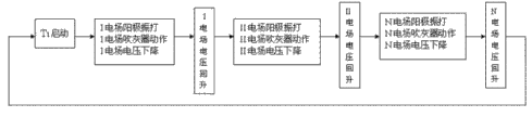
Fig. 5 is anode rapping of the present invention and step-down control sketch map thereof.
Fig. 6 is cathode rapping of the present invention and step-down control sketch map thereof.
Fig. 7 is a soot blower mounting structure sketch map of the present invention.
Fig. 8 is a keen current U-I curve map under the best slope energy conservation pattern.
Fig. 9 is the automatic tracking Control sketch map of flex point in each electric field.
Wherein 1 represent ceiling, 2 represent the ultrasonic wave soot blower, and 3 represent pole plate suspention beam, and 4 represent pole plate.
The specific embodiment
Below in conjunction with accompanying drawing the present invention is done detailed explanation:
1, the power supply with high voltage electrostatic dust precipitator changes three phase supply into by single phase power supply
As shown in Figure 1, single-phase high voltage rectifier power source basic principle: single-phase 380VAC/50HZ industrial frequency AC signal, through the controllable silicon phase-shift voltage regulating, transformer boosts and rectification after waveform be the 100HZ fluctuating signal
As shown in Figure 2; High voltage electrostatic dust precipitator of the present invention adopts the three-phase high-voltage rectifier power source, basic principle: with three-phase system is to adopt three-phase 380V to exchange input, through three tunnel six controllable silicon inverse parallel pressure regulation; Boost through three-phase transformer; Three-phase bridge rectification, and be unified into one tunnel high direct voltage signal and be added to electric cleaner, novel three phase mains characteristics: three-phase equilibrium, high efficient and reliable, energy-conservation significantly; Improve efficiency of dust collection, reduce dust exhausting concentration.
Shown in Figure 3, in 51kV, electric field begins flashover to single phase poaer supply secondary voltage mean value (gauge outfit show value), because of its actual crest voltage is that 69kV has reached the flashover point; And three-phase high-voltage rectifier power source (DHEP) is little owing to the output waveform fluctuation, and the approaching and crest voltage of its average voltage is 68 kV, and its secondary effective current can be greatly enhanced simultaneously.
Novel three-phase high-voltage rectifier power source is except energy-conservation; Another positive meaning is: under the working condition lower with single phase poaer supply and flashover point, that secondary current output is very low, can significantly improve average voltage and effective current mean value with novel three phase mains.
2, with each electric field yin, yang pole plate rapping mode of high-voltage electrostatic dust separator by pole plate respectively rapping change each electric field time-delay rapping into; And reduce the operating voltage of this electric field in the time of the rapping apparatus action, improve rapping efficient;
High-voltage electrostatic dust separator is generally by first electric field, second electric field, the 3rd electric field ... The N electric field is formed, and each electric field all is the structure that is arranged to a row by the cathode-anode plate equidistant parallel, through PLC control system or DCS control default time T
1, in time T
1Gather dust on the positive plate in first electric field, the voltage in first electric field reduces, in time T before
1When arriving, PLC control system or DCS control system realize the anode beater rapping in first electric field, realize that simultaneously the soot blower in first electric field blows ash, duration section △ T
1After, the dust on the first electric field inner anode plate reduces, and the voltage in first electric field gos up; The positive plate elapsed time T of second electric field then
1+ △ T
1Time, gather dust on the positive plate of second electric field, the voltage in second electric field reduces, PLC control system or DCS control system realize the anode beater rapping in second electric field, realize that simultaneously the soot blower in second electric field blows ash, duration section △ T
2After, the dust on the second electric field inner anode plate reduces, and the voltage in second electric field gos up, and each this rapping method of electric field continuity is until the positive plate elapsed time of N electric field T
1+ △ T
1+ △ T
2+ ... △ T
N-1Time, gather dust on the positive plate in the N electric field, the voltage in the N electric field reduces, and PLC control system or DCS control system realize the anode beater rapping in the N electric field, realize that simultaneously the soot blower in the N electric field blows ash, duration section △ T
NAfter, the dust on the N electric field inner anode plate reduces, and the voltage in the N electric field gos up, then elapsed time T
1After, enter into the anode rapping of first electric field again;
Through PLC control system or DCS control default time T
2, in time T
2Gather dust on the minus plate in first electric field, the voltage in first electric field reduces, in time T before
2When arriving, PLC control system or DCS control system realize the cathode rapping hammer rapping in first electric field, realize that simultaneously the soot blower in first electric field blows ash, duration section △ T
1After, the dust on the first electric field inner cathode plate reduces, and the voltage in first electric field gos up; The minus plate elapsed time T of second electric field then
2+ △ T
1Time, gather dust on the minus plate of second electric field, the voltage in second electric field reduces, PLC control system or DCS control system realize the cathode rapping hammer rapping in second electric field, realize that simultaneously the soot blower in second electric field blows ash, duration section △ T
2After, the dust on the second electric field inner cathode plate reduces, and the voltage in second electric field gos up, and each this rapping method of electric field continuity is until the minus plate elapsed time of N electric field T
2+ △ T
1+ △ T
2+ ... △ T
N-1Time, gather dust on the minus plate in the N electric field, the voltage in the N electric field reduces, and PLC control system or DCS control system realize the cathode rapping hammer rapping in the N electric field, realize that simultaneously the soot blower in the N electric field blows ash, duration section △ T
NAfter, the dust on the N electric field inner cathode plate reduces, and the voltage in the N electric field gos up, then elapsed time T
2After, enter into the cathode rapping of first electric field again;
Described rapping method realizes that through PLC control system or DCS control system time-delay rapping and the soot blower of each electric field blow ash and carry out simultaneously.
Former control structure is as shown in Figure 4, and its each electric field rapping apparatus starts simultaneously, the rapping respectively of electric field yin, yang pole plate; Cause reentrainment of dust, influenced the efficiency of dust collection of high-voltage electrostatic dust separator greatly.
Like Fig. 5, shown in Figure 6, anode of the present invention, cathode rapping and each electric field step-down control;
The numerical value that its operating voltage reduced when the present invention was controlled at the action of each electric field rapping apparatus adopts ladder control principle, and promptly an electric field U1 is lower than two electric field U2...... Un and effectively controls reentrainment of dust, U1<U2<... ..<Un.
As shown in Figure 7; Install the ultrasonic wave soot blower additional on each electric field pole plate top; Because cathode-anode plate is arranged in parallel into several rows of structure, several rows of then cathode-anode plate is fixedly installed on the pole plate suspention beam, and ultrasonic wave soot blower equidistant placement is on pole plate suspention beam; The ash mouthful aligning pole plate that blows of ultrasonic wave soot blower blows ash downwards, and the ultrasonic wave soot blower is controlled through PLC control system or DCS control system.
4, because different its work (U-I) point of inflexion on a curve of the load of each electric field of high voltage electrostatic dust precipitator electric current is also inequality, and the load of random groups operation and becoming.
The present invention is provided with the automatic trace routine of electric field keen current in the module of the PLC of each electric field control system or DCS control system; (getting into PLC or DCS control program) realized each field operation flex point from motion tracking, thereby further improves the efficiency of dust collection of each electric field of high voltage electrostatic dust precipitator.
Shown in Figure 8, keen current U-I curve map under the best slope energy conservation pattern
B point current ratio a point significantly improves among the figure, and voltage raises seldom.Ib>>Ia; The a point is a best operating point, also claims " flex point ".
Ia is " flex point " electric current, and Δ t is the control current i kz action delay time limit, is confirmed by the actual parameter of each electric field.
Fig. 9 is the automatic trace routine theory diagram of keen current; The secondary current of high-pressure electrostatic electric cleaner electric field less than or during greater than keen current, controller changes the size of thyristor operating angle, change secondary current and secondary voltage; Reach keen current, make it run on this state; Time-delay △ T is then again from motion tracking new keen current and corresponding secondary voltage, up to new running status.
The present invention changes former high-voltage electrostatic dust separator single-phase high voltage rectifier power source into the three-phase high-voltage rectifier power source; With the rapping of high voltage electrostatic dust precipitator anode and cathode by pole plate respectively rapping change each electric field time-delay rapping into; And install the ultrasonic wave soot blower additional; Each electric field adopts the automatic trace routine of knee voltage to realize that each field operation average voltage of high-voltage electrostatic dust separator approaches crest voltage, significantly improves electric-field intensity; The use of software of the present invention significantly improves each electric field pole plate rapping efficient, makes operating dust stratification reduce to minimum, thereby makes the optimum state that is operated in of pole plate, has further improved efficiency of dust collection.Because each pole plate operates in and has reduced operating corona current under the less situation of dust stratification and realized energy-conservation.
Claims (7)
1. high-voltage electrostatic dust separator rapping soot blower; Comprise that the target plate carries out the anode vibration body that the cathode rapping mechanism of rapping, antianode plate carry out rapping; Described positive plate and minus plate are arranged on the bottom of pole plate suspention beam; Cathode rapping mechanism comprises cathode rapping axle and cathode rapping hammer; The anode vibration body comprises anode rapping shaft and anode beater, and anode vibration body and cathode rapping mechanism all control system's control connection with PLC control system or DCS, and it is characterized in that: the suspention beam on the top of minus plate and positive plate is provided with soot blower.
2. high-voltage electrostatic dust separator rapping soot blower according to claim 1, it is characterized in that: described soot blower is electrically connected with power supply, and controls system's control connection with PLC control system or DCS.
3. high-voltage electrostatic dust separator rapping soot blower according to claim 1 is characterized in that: described soot blower adopts the ultrasonic wave soot blower, and this ultrasonic wave soot blower equidistant placement is on the top of pole plate suspention beam.
4. high-voltage electrostatic dust separator rapping soot blower according to claim 1 is characterized in that: this device adopts the three-phase high-voltage rectifier power source.
5. the rapping method of a high-voltage electrostatic dust separator rapping soot blower as claimed in claim 1 is characterized in that: through PLC control system or DCS control default time T
1, in time T
1Gather dust on the positive plate in first electric field, the voltage in first electric field reduces, in time T before
1When arriving, PLC control system or DCS control system realize the anode beater rapping in first electric field, realize that simultaneously the soot blower in first electric field blows ash, duration section △ T
1After, the dust on the first electric field inner anode plate reduces, and the voltage in first electric field gos up; The positive plate elapsed time T of second electric field then
1+ △ T
1Time, gather dust on the positive plate of second electric field, the voltage in second electric field reduces, PLC control system or DCS control system realize the anode beater rapping in second electric field, realize that simultaneously the soot blower in second electric field blows ash, duration section △ T
2After, the dust on the second electric field inner anode plate reduces, and the voltage in second electric field gos up, and each this rapping method of electric field continuity is until the positive plate elapsed time of N electric field T
1+ △ T
1+ △ T
2+ ... △ T
N-1Time, gather dust on the positive plate in the N electric field, the voltage in the N electric field reduces, and PLC control system or DCS control system realize the anode beater rapping in the N electric field, realize that simultaneously the soot blower in the N electric field blows ash, duration section △ T
NAfter, the dust on the N electric field inner anode plate reduces, and the voltage in the N electric field gos up, then elapsed time T
1After, enter into the anode rapping of first electric field again;
Through PLC control system or DCS control default time T
2, in time T
2Gather dust on the minus plate in first electric field, the voltage in first electric field reduces, in time T before
2When arriving, PLC control system or DCS control system realize the cathode rapping hammer rapping in first electric field, realize that simultaneously the soot blower in first electric field blows ash, duration section △ T
1After, the dust on the first electric field inner cathode plate reduces, and the voltage in first electric field gos up; The minus plate elapsed time T of second electric field then
2+ △ T
1Time, gather dust on the minus plate of second electric field, the voltage in second electric field reduces, PLC control system or DCS control system realize the cathode rapping hammer rapping in second electric field, realize that simultaneously the soot blower in second electric field blows ash, duration section △ T
2After, the dust on the second electric field inner cathode plate reduces, and the voltage in second electric field gos up, and each this rapping method of electric field continuity is until the minus plate elapsed time of N electric field T
2+ △ T
1+ △ T
2+ ... △ T
N-1Time, gather dust on the minus plate in the N electric field, the voltage in the N electric field reduces, and PLC control system or DCS control system realize the cathode rapping hammer rapping in the N electric field, realize that simultaneously the soot blower in the N electric field blows ash, duration section △ T
NAfter, the dust on the N electric field inner cathode plate reduces, and the voltage in the N electric field gos up, then elapsed time T
2After, enter into the cathode rapping of first electric field again;
Described rapping method realizes that through PLC control system or DCS control system time-delay rapping and the soot blower of each electric field blow ash and carry out simultaneously.
6. the rapping method of high-voltage electrostatic dust separator rapping soot blower according to claim 5 is characterized in that: described △ T
1, △ T
2, △ T
3△ T
NIncrease gradually.
7. the rapping method of high-voltage electrostatic dust separator rapping soot blower according to claim 5; It is characterized in that: described PLC control system or DCS control system are provided with keen current for each electric field; After having adsorbed dust owing to each electric field; The electric field electric current reduces, and makes the secondary current of electric field less than keen current, the size of PLC control system or the DCS control system thyristor operating angle through changing the three-phase high-voltage rectifier power source; Make secondary current reach keen current, thereby the intensity of electric field improve.
Priority Applications (1)
| Application Number | Priority Date | Filing Date | Title |
|---|---|---|---|
| CN 201110317247 CN102397818B (en) | 2011-10-19 | 2011-10-19 | Rapping soot blowing device for high-voltage electrostatic dust collector and rapping method thereof |
Applications Claiming Priority (1)
| Application Number | Priority Date | Filing Date | Title |
|---|---|---|---|
| CN 201110317247 CN102397818B (en) | 2011-10-19 | 2011-10-19 | Rapping soot blowing device for high-voltage electrostatic dust collector and rapping method thereof |
Publications (2)
| Publication Number | Publication Date |
|---|---|
| CN102397818A true CN102397818A (en) | 2012-04-04 |
| CN102397818B CN102397818B (en) | 2013-12-18 |
Family
ID=45880699
Family Applications (1)
| Application Number | Title | Priority Date | Filing Date |
|---|---|---|---|
| CN 201110317247 Expired - Fee Related CN102397818B (en) | 2011-10-19 | 2011-10-19 | Rapping soot blowing device for high-voltage electrostatic dust collector and rapping method thereof |
Country Status (1)
| Country | Link |
|---|---|
| CN (1) | CN102397818B (en) |
Cited By (6)
| Publication number | Priority date | Publication date | Assignee | Title |
|---|---|---|---|---|
| CN103567071A (en) * | 2012-07-31 | 2014-02-12 | 上海冶金矿山机械厂 | Anode plate with spraying and blowing functions in dust remover |
| CN103769298A (en) * | 2012-10-18 | 2014-05-07 | 金东纸业(江苏)股份有限公司 | Electrostatic precipitation system |
| CN104971824A (en) * | 2015-07-06 | 2015-10-14 | 华能国际电力开发公司铜川照金电厂 | Combined automatic dust control system based on dry electrical dust precipitator and wet dust collector |
| CN109969741A (en) * | 2019-03-19 | 2019-07-05 | 张家港市华申工业橡塑制品有限公司 | A kind of dust collect plant |
| CN110124866A (en) * | 2019-04-01 | 2019-08-16 | 新疆天富能源股份有限公司 | A kind of ESP Efficiency optimization method |
| CN112495588A (en) * | 2019-09-13 | 2021-03-16 | 赵红文 | Reverse-order rapping method of electric precipitation anode plate for flue gas treatment |
Citations (7)
| Publication number | Priority date | Publication date | Assignee | Title |
|---|---|---|---|---|
| JPS62201660A (en) * | 1986-02-27 | 1987-09-05 | Mitsubishi Heavy Ind Ltd | Operating method for stack gas treatment device |
| CN1554487A (en) * | 2003-12-26 | 2004-12-15 | 高国纯 | Industrial electric dust removing device purifying system |
| CN2902469Y (en) * | 2006-04-20 | 2007-05-23 | 上海梅山钢铁股份有限公司 | Composite electric dust collector rapping device |
| CN201147721Y (en) * | 2007-08-29 | 2008-11-12 | 于力 | Multi-sound wave combined dust removing electric dust collector |
| EP2087938A1 (en) * | 2008-02-08 | 2009-08-12 | ALSTOM Technology Ltd | A method and a device for controlling the rapping of an ESP |
| CN201616764U (en) * | 2010-03-11 | 2010-10-27 | 中冶集团鞍山冶金设计研究总院自动化工程有限公司 | High-voltage direct-current power supply controlled by frequency converter |
| CN201684664U (en) * | 2010-06-03 | 2010-12-29 | 大连嘉禾工业控制技术有限公司 | Electromagnetic vibrating-hitting control device of electric precipitator |
-
2011
- 2011-10-19 CN CN 201110317247 patent/CN102397818B/en not_active Expired - Fee Related
Patent Citations (8)
| Publication number | Priority date | Publication date | Assignee | Title |
|---|---|---|---|---|
| JPS62201660A (en) * | 1986-02-27 | 1987-09-05 | Mitsubishi Heavy Ind Ltd | Operating method for stack gas treatment device |
| CN1554487A (en) * | 2003-12-26 | 2004-12-15 | 高国纯 | Industrial electric dust removing device purifying system |
| CN2902469Y (en) * | 2006-04-20 | 2007-05-23 | 上海梅山钢铁股份有限公司 | Composite electric dust collector rapping device |
| CN201147721Y (en) * | 2007-08-29 | 2008-11-12 | 于力 | Multi-sound wave combined dust removing electric dust collector |
| EP2087938A1 (en) * | 2008-02-08 | 2009-08-12 | ALSTOM Technology Ltd | A method and a device for controlling the rapping of an ESP |
| CN101939108A (en) * | 2008-02-08 | 2011-01-05 | 阿尔斯托姆科技有限公司 | A method and a device for controlling the rapping of an ESP |
| CN201616764U (en) * | 2010-03-11 | 2010-10-27 | 中冶集团鞍山冶金设计研究总院自动化工程有限公司 | High-voltage direct-current power supply controlled by frequency converter |
| CN201684664U (en) * | 2010-06-03 | 2010-12-29 | 大连嘉禾工业控制技术有限公司 | Electromagnetic vibrating-hitting control device of electric precipitator |
Cited By (6)
| Publication number | Priority date | Publication date | Assignee | Title |
|---|---|---|---|---|
| CN103567071A (en) * | 2012-07-31 | 2014-02-12 | 上海冶金矿山机械厂 | Anode plate with spraying and blowing functions in dust remover |
| CN103769298A (en) * | 2012-10-18 | 2014-05-07 | 金东纸业(江苏)股份有限公司 | Electrostatic precipitation system |
| CN104971824A (en) * | 2015-07-06 | 2015-10-14 | 华能国际电力开发公司铜川照金电厂 | Combined automatic dust control system based on dry electrical dust precipitator and wet dust collector |
| CN109969741A (en) * | 2019-03-19 | 2019-07-05 | 张家港市华申工业橡塑制品有限公司 | A kind of dust collect plant |
| CN110124866A (en) * | 2019-04-01 | 2019-08-16 | 新疆天富能源股份有限公司 | A kind of ESP Efficiency optimization method |
| CN112495588A (en) * | 2019-09-13 | 2021-03-16 | 赵红文 | Reverse-order rapping method of electric precipitation anode plate for flue gas treatment |
Also Published As
| Publication number | Publication date |
|---|---|
| CN102397818B (en) | 2013-12-18 |
Similar Documents
| Publication | Publication Date | Title |
|---|---|---|
| CN102397818B (en) | Rapping soot blowing device for high-voltage electrostatic dust collector and rapping method thereof | |
| CN103028494B (en) | A kind of electrostatic precipitation pulse power source control system | |
| CN201613182U (en) | Corona blue light dust collector | |
| CN201751006U (en) | High-frequency power supply controller special for electrostatic dust removal | |
| CN103394412A (en) | High frequency pulse power supply for electric dedusting | |
| CN109365134B (en) | Automatic control method of dust removal system in coal-fired power generation system | |
| CN103817009A (en) | Honeycomb electrofilter with high flow rate | |
| CN203018208U (en) | Electrostatic dust-removal pulse power source control system | |
| CN112016808B (en) | High-efficiency electrostatic dust collector | |
| CN219268807U (en) | Solar photovoltaic panel surface electrostatic dust collection device | |
| CN102233301A (en) | High-frequency pulse power supply for electrostatic dust collector | |
| CN204735342U (en) | Electric dust collector | |
| CN1879972A (en) | Solar energy static dedusting system | |
| CN106984438A (en) | LD type ultra-low concentration discharge electrostatic precipitator | |
| CN202343326U (en) | Optimized power device for electric dust removing | |
| CN102407187A (en) | Optimized power supply device for electric precipitation | |
| CN208098384U (en) | A kind of wide space ESP | |
| CN102284365B (en) | A kind of pulse power source device for electro-precipitator | |
| CN105709935A (en) | Pulsed power supply for electrostatic dust collection and generation method of pulsed power supply | |
| CN203425920U (en) | Electrostatic dedusting system | |
| CN209501962U (en) | A kind of electric precipitator having energy storage multiplication of voltage function | |
| CN202479047U (en) | Pulse power supply unit for electric dust remover | |
| CN202700655U (en) | Dedusting circuit of boiler in thermal power plant | |
| CN203140160U (en) | Electrostatic dust collector for purifying flue gas and cathode device for electrostatic dust collector | |
| CN205887177U (en) | New and effective wet -type electrostatic precipitator based on pulse generator |
Legal Events
| Date | Code | Title | Description |
|---|---|---|---|
| C06 | Publication | ||
| PB01 | Publication | ||
| C10 | Entry into substantive examination | ||
| SE01 | Entry into force of request for substantive examination | ||
| C14 | Grant of patent or utility model | ||
| GR01 | Patent grant | ||
| CF01 | Termination of patent right due to non-payment of annual fee |
Granted publication date: 20131218 Termination date: 20171019 |
|
| CF01 | Termination of patent right due to non-payment of annual fee |