CN102359497B - Low noise conical roller bearing - Google Patents
Low noise conical roller bearing Download PDFInfo
- Publication number
- CN102359497B CN102359497B CN 201110248313 CN201110248313A CN102359497B CN 102359497 B CN102359497 B CN 102359497B CN 201110248313 CN201110248313 CN 201110248313 CN 201110248313 A CN201110248313 A CN 201110248313A CN 102359497 B CN102359497 B CN 102359497B
- Authority
- CN
- China
- Prior art keywords
- ring
- retainer
- seal ring
- inner ring
- bearing
- Prior art date
- Legal status (The legal status is an assumption and is not a legal conclusion. Google has not performed a legal analysis and makes no representation as to the accuracy of the status listed.)
- Expired - Fee Related
Links
Images
Abstract
The present invention relates to a low noise conical roller bearing. The bearing comprises an inner ring, an outer ring, conical rollers and a conical ring-shaped cage, and further comprises a sealing ring. An inner side end of the sealing ring is provided with a scarf connection groove corresponding to a large diameter end of the conical ring-shaped cage. The conical rollers can be rotatably supported on the cage. The cage is arranged on the outer side of the inner ring. The outer ring is arranged on the outer side of the cage. The inner ring and the outer ring form a rotatable connection by the rollers. The sealing ring is sleeved on an outer circumference side surface of one end of the inner ring, and is connected with the cage by the scarf connection groove. The part corresponding to the inner end of the sealing ring presses and contacts the corresponding end surface of the outer ring. The bearing has the following advantages that: the noise generated during the collision of the rollers and the cage can be substantially reduced; a shielding effect is provided for the noise generated inside the bearing; effects of sealing and dust proof are achieved.
Description
Technical field
The present invention relates to a kind of low noise tapered roller bearing.
Background technique
General tapered roller bearing all is to be made of four big parts such as outer ring, inner ring, roller, retainers now, sees also Fig. 2.In use, inner ring is contained on the axle journal, rotate with axle, the outer ring is contained in the bearing hole of support or part, in most cases does not rotate the outer ring, owing to rotating the frictional force that produces between the Internal and external cycle relatively roller is rolled along raceway, and retainer does not contact, and drives retainer by roller and rotates along axis with inside and outside circle.
Tapered roller bearing can bear axially and the active force of both direction radially simultaneously, therefore in most cases all is used on the poor equipment of working conditions such as automobile, engineering machinery, farm machinery.Because tapered roller bearing self do not have seal arrangement, very easily be subjected to the invasion of foreign matters such as dust and cause early failue, thereby shorten the working life of bearing greatly.Tapered roller bearing is when high speed rotating in addition, the rotation of retainer is to drive by pushing of roller, axially easily producing play, roller since unbalance stress in various degree crooked can take place and produce collision with retainer, thereby cause the noise of bearing bigger, can produce obvious noise when serious and pollute, influence surrounding environment.This is a tapered roller bearing owing to two defectives that are difficult to eliminate that the restriction of structure brings.
Summary of the invention
The object of the invention is to overcome the deficiency of above-mentioned prior art, and a kind of good seal performance, dust-tight low noise tapered roller bearing are provided, and is specifically realized by following technological scheme:
A kind of low noise tapered roller bearing, comprise inner ring, the outer ring, tapered roller and conical ring shape retainer, also comprise seal ring, described seal ring medial extremity is provided with and the corresponding scarfing slot of described conical ring shape retainer larger diameter end, described roller is rotating to be bearing on the retainer, retainer places the outside of inner ring, the outer ring places the outside of retainer, inner ring and outer ring are rotatably connected by roller, seal ring is socketed on the excircle side of inner ring large-flange, and is connected with retainer by described scarfing slot, described seal ring and inner ring large-flange and retainer employing drive fit, inner ring rotates together by frictional force drive seal ring when rotation, and seal ring drives also rotation together of retainer by scarfing slot, the rotation of retainer ends the dependence upon pushing of roller and produces, and can not produce axial float when rotating, thereby has reduced the collision of roller and retainer, greatly reduce the noise that produces owing to both collisions, the inner counterpart of seal ring is pressed and is touched on the corresponding end face of outer ring.
Described bearing further design is, described low noise tapered roller bearing, and the end face of described seal ring medial extremity is provided with the conical surface of arc, and described scarfing slot is arranged on this arc conical surface.
Seal ring that tapered roller bearing provided by the invention adopts and inner ring big shelves limit and retainer adopt drive fit, inner ring drives seal ring by frictional force when rotating and retainer rotates together, thereby the noise that is produced when greatly reducing the collision of roller and retainer, can play screen simultaneously to the noise that bearing inside produces and close effect, reach sealing, dust-tight effect again.
Description of drawings
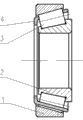
Fig. 1 is the structural representation of tapered roller bearing of the present invention.
Fig. 2 is the structural representation of existing tapered roller bearing.
Among the figure, 1 outer ring, 2 inner rings, 3 rollers, 4 retainers, 5 seal rings.
Embodiment
Below in conjunction with drawings and the specific embodiments the present invention is done and to further specify:
Contrast Fig. 1, the bearing of present embodiment is provided with by the standard model of 32210 tapered roller bearings, mainly is made up of outer ring 1, inner ring 2, tapered roller 3, retainer 4 and seal ring 5.Several tapered rollers 3 are rotatably supported on the retainer 4.Retainer 4 is the conical ring shape, places the outside of inner ring 2 essentially concentric, and outer ring 1 places the outside of retainer 4, and with inner ring 2 essentially concentrics, inner ring 2 is rotatably connected by roller 3 with outer ring 1.The medial extremity of seal ring 5 its axial directions is provided with and the corresponding scarfing slot 51 of conical ring shape retainer larger diameter end, seal ring 5 tightly fits on the excircle of inner ring 2 large-flanges, and be connected with retainer 4 by scarfing slot 51, the axial inner side end of seal ring 5 is provided with the arc conical surface 52, scarfing slot 51 is arranged on this arc conical surface, the counterpart of the described medial extremity of seal ring is pressed and is touched on the corresponding end face 11 of outer ring 2, seal ring is tightly connected with the corresponding end face 11 of outer ring 2, and make between seal ring and outer ring and the roller and keep certain space, so that heat radiation.
Tapered roller bearing provided by the invention, the one end interlocking of its retainer is in the scarfing slot 51 of seal ring 5, when inner ring rotates, rotate together by scarfing slot drive seal ring and retainer, the rotation of retainer ends the dependence upon pushing of roller and produces, and can not produce axial float when rotating, thereby reduce the collision of roller and retainer, greatly reduce the noise that produces owing to both collisions.Test shows that the noise ratio similar bearing when tapered roller bearing of the present invention is worked hangs down 10% at least.Seal ring of the present invention also has the noise that bearing inside is produced and plays the effect that screen closes except that having conventional arriving sealing, the dust-tight effect simultaneously.
Claims (2)
1. low noise tapered roller bearing, comprise inner ring, the outer ring, tapered roller and conical ring shape retainer, it is characterized in that: also comprise seal ring, described seal ring medial extremity is provided with and the corresponding scarfing slot of described conical ring shape retainer larger diameter end, described roller is rotating to be bearing on the retainer, retainer places the outside of inner ring, the outer ring places the outside of retainer, inner ring and outer ring are rotatably connected by roller, the seal ring close-fitting is on the excircle of inner ring large-flange, and be connected with retainer by described scarfing slot, described seal ring and inner ring large-flange and retainer adopt drive fit, inner ring drives seal ring by frictional force and rotates together when rotating, and seal ring drives also rotation together of retainer by scarfing slot, the rotation of retainer ends the dependence upon pushing of roller and produces, and can not produce axial float when rotating, thereby reduced the collision of roller and retainer, greatly reduce the noise that produces owing to both collisions, seal ring medial extremity counterpart pressure is touched on the end face of the corresponding end of outer ring.
2. low noise tapered roller bearing according to claim 1, the end face of described seal ring medial extremity is provided with the arc conical surface, and described scarfing slot is arranged on this arc conical surface.
Priority Applications (1)
| Application Number | Priority Date | Filing Date | Title |
|---|---|---|---|
| CN 201110248313 CN102359497B (en) | 2011-08-26 | 2011-08-26 | Low noise conical roller bearing |
Applications Claiming Priority (1)
| Application Number | Priority Date | Filing Date | Title |
|---|---|---|---|
| CN 201110248313 CN102359497B (en) | 2011-08-26 | 2011-08-26 | Low noise conical roller bearing |
Publications (2)
| Publication Number | Publication Date |
|---|---|
| CN102359497A CN102359497A (en) | 2012-02-22 |
| CN102359497B true CN102359497B (en) | 2013-07-24 |
Family
ID=45584864
Family Applications (1)
| Application Number | Title | Priority Date | Filing Date |
|---|---|---|---|
| CN 201110248313 Expired - Fee Related CN102359497B (en) | 2011-08-26 | 2011-08-26 | Low noise conical roller bearing |
Country Status (1)
| Country | Link |
|---|---|
| CN (1) | CN102359497B (en) |
Families Citing this family (2)
| Publication number | Priority date | Publication date | Assignee | Title |
|---|---|---|---|---|
| CN103790939A (en) * | 2012-10-31 | 2014-05-14 | 优必胜(上海)精密轴承制造有限公司 | Low-noise tapered roller bearing |
| DE102015218625A1 (en) * | 2015-09-28 | 2017-03-30 | Aktiebolaget Skf | Seal for a wheel bearing assembly |
Citations (3)
| Publication number | Priority date | Publication date | Assignee | Title |
|---|---|---|---|---|
| DE2753340A1 (en) * | 1977-11-30 | 1979-05-31 | Daimler Benz Ag | Ball or roller bearing - has seal and cage formed as separate components which may be clipped together |
| CN101115933A (en) * | 2005-02-11 | 2008-01-30 | S.N.R.鲁尔门斯公司 | Conical roller bearing comprising a filter cage |
| CN202188016U (en) * | 2011-08-26 | 2012-04-11 | 凌翔 | Low-noise tapered roller bearing |
Family Cites Families (2)
| Publication number | Priority date | Publication date | Assignee | Title |
|---|---|---|---|---|
| JPH0630530U (en) * | 1992-09-24 | 1994-04-22 | 光洋精工株式会社 | Tapered roller bearing with seal |
| DE102010005473A1 (en) * | 2010-01-23 | 2011-07-28 | Schaeffler Technologies GmbH & Co. KG, 91074 | roller bearing |
-
2011
- 2011-08-26 CN CN 201110248313 patent/CN102359497B/en not_active Expired - Fee Related
Patent Citations (3)
| Publication number | Priority date | Publication date | Assignee | Title |
|---|---|---|---|---|
| DE2753340A1 (en) * | 1977-11-30 | 1979-05-31 | Daimler Benz Ag | Ball or roller bearing - has seal and cage formed as separate components which may be clipped together |
| CN101115933A (en) * | 2005-02-11 | 2008-01-30 | S.N.R.鲁尔门斯公司 | Conical roller bearing comprising a filter cage |
| CN202188016U (en) * | 2011-08-26 | 2012-04-11 | 凌翔 | Low-noise tapered roller bearing |
Non-Patent Citations (1)
| Title |
|---|
| JP实开平6-30530U 1994.04.22 |
Also Published As
| Publication number | Publication date |
|---|---|
| CN102359497A (en) | 2012-02-22 |
Similar Documents
| Publication | Publication Date | Title |
|---|---|---|
| JP5312514B2 (en) | Crossed roller bearing | |
| CN102418740A (en) | A three row roller bearing, in particular for a wind turbine | |
| CN102359497B (en) | Low noise conical roller bearing | |
| CN107299937A (en) | The combination bearing of elevator dish traction machine | |
| CN105402255B (en) | Double-layer seal matches bearing | |
| CN202188016U (en) | Low-noise tapered roller bearing | |
| CN107269689A (en) | A kind of combination bearing suitable for the dish-shaped traction machine of elevator | |
| CN103657773A (en) | Roller bearing type eccentric sleeve mechanism | |
| CN203285841U (en) | Self-aligning roller bearing | |
| CN202690766U (en) | Pivoting support structure | |
| CN203067539U (en) | Novel rolling bearing structure | |
| CN201171170Y (en) | Axial bidirectional locating structure for motor bearings | |
| CN202612380U (en) | Pulley ball bearing of jacquard loom | |
| CN201934516U (en) | Bearing | |
| JP2013210003A (en) | Tandem type double row angular ball bearing with seal | |
| CN203516452U (en) | Insert bearing with concentric sleeve | |
| CN103133541B (en) | The turntable bearing of seal and the use seal for turntable bearing | |
| CN201382084Y (en) | Automobile wheel hub bearing unit | |
| KR20120010785A (en) | Multiple bearing unit with integrating a housing | |
| CN206364639U (en) | A kind of bearing arrangement of vertical machine | |
| CN105240409A (en) | Bearing without holding frame | |
| CN201893642U (en) | Axial limit device of motor bearing | |
| CN206845830U (en) | automobile differential, bearing combined structure | |
| CN205101418U (en) | Bearing arrangement of arable land tractor -ploughing sword | |
| CN203522433U (en) | Axial limiting device of motor rotor |
Legal Events
| Date | Code | Title | Description |
|---|---|---|---|
| C06 | Publication | ||
| PB01 | Publication | ||
| C10 | Entry into substantive examination | ||
| SE01 | Entry into force of request for substantive examination | ||
| C14 | Grant of patent or utility model | ||
| GR01 | Patent grant | ||
| CF01 | Termination of patent right due to non-payment of annual fee |
Granted publication date: 20130724 Termination date: 20160826 |
|
| CF01 | Termination of patent right due to non-payment of annual fee |