CN102354936A - Economic bus duct of copper conductor - Google Patents
Economic bus duct of copper conductor Download PDFInfo
- Publication number
- CN102354936A CN102354936A CN2011102892118A CN201110289211A CN102354936A CN 102354936 A CN102354936 A CN 102354936A CN 2011102892118 A CN2011102892118 A CN 2011102892118A CN 201110289211 A CN201110289211 A CN 201110289211A CN 102354936 A CN102354936 A CN 102354936A
- Authority
- CN
- China
- Prior art keywords
- conductor
- bus duct
- phase
- copper
- conductor layer
- Prior art date
- Legal status (The legal status is an assumption and is not a legal conclusion. Google has not performed a legal analysis and makes no representation as to the accuracy of the status listed.)
- Pending
Links
Images


Abstract
The invention discloses an economic bus duct of a copper conductor, comprising at least one bus duct unit, wherein each bus duct unit comprises at least one conductor layer; each conductor layer comprises at least one phase conductor, and the adjacent phase conductors are insulated mutually; and each phase conductor comprises at least one conductive body, and the conductive body is a copper conductive body of which the thickness is 0.4-2mm. Compared with the prior art, the economic bus duct has the beneficial effects that the skin effect is utilized to decrease the thickness of the copper conductive body, thus improving the current carrying capacity, saving the application amount of copper, and lightening the weight of the whole device; and magnesium alloys are used to manufacture a shell, thus the weight of the whole device is lightened further, the intensity of the shell is strengthened, the shell has more excellent heat dispersion performance, and the current carrying capacity of the bus duct is improved.
Description
Technical field
The present invention relates to a kind of electric power conveying route, relate in particular to the economical bus duct of a kind of copper conductor.
Background technology
Along with the development of society, skyscraper, industrial premises, hotel, airport, station, synthesis building electricity consumption load sharply increase.Be more than the twice of cable the useful life of bus duct, and be not easy breaking out of fire, current capacity is big, voltage drop is little, easy control of temperature, thereby increasing project selects for use bus duct to replace the power cable power supply.
For example; Chinese patent 200420095532.X discloses a kind of high current carrying bus groove; It comprises the copper electric conductor, is positioned at insulating barrier, first housing on the copper electric conductor; First housing comprises two cover plates, two side seat boards, two bolts; Side seat board two ends have a circular hole respectively, and two bolts pass the circular hole at two side seat board two ends respectively; On the shank of bolt between the seat board of both sides, there are lid insulation phase isolation block, several recessed collets to be arranged in order; Between lid insulation phase isolation block and the recessed collets, have folder collets respectively at least between recessed collets and the recessed collets, lid insulation phase isolation block and press from both sides collets, press from both sides between collets and the recessed collets copper electric conductor is arranged; Cover plate cooperates with the side seat board, and the copper electric conductor is the superimposed body of the copper electric conductor sheet of two tape insulation layers at least.
One Chinese patent application 201010611084.4 discloses a kind of wind-powered electricity generation special mother wire casing, and it comprises heterogeneous bus pipe conductor, insulation supporter, fixture, conductor flexible connecting member, the first housing flexible connecting member; Wherein heterogeneous bus pipe conductor is hollow, and to be pressed into line nose in its end.
Chinese patent 200680055079.1 applications disclose a kind of bus duct system of high ampere electric power transfer, and each comprises the multiple tracks conductor mutually, and this multiple tracks conductor comprises a plurality of long strips parallel to each other, and the scope of the surface area/volume ratio of each long strips is at 0.45mm
2/ mm
3To 1.15mm
2/ mm
3In.The surface area that increases has reduced the kelvin effect ratio, and kelvin effect is decided (when the thickness increase of bar, kelvin effect increases) than the width/thickness ratio of looking strip conductor.
One Chinese patent application 200810110741.X discloses a kind of bus duct device; It comprises conductor and the ground wire that links to each other with conductor; Wherein the connecting portion of conductor is provided with the brace that comprises copper layer and aluminium lamination, and the contact site of copper layer is the copper electric conductor, and the contact site of aluminium lamination is an aluminium conductor.
One Chinese patent application 200610084994.5 discloses a kind of with the row core of aluminium as the bus duct busbar, with outer contact and the installation contact-making surface of certain thickness copper coin material as the bus duct busbar, constitutes copper-claded aluminium bus slot conductive bar.
One Chinese patent application 201010132828.4 discloses a kind of low resistance, low reactance, line loss is low, consumptive material is few high-efficiency heat radiation structure low-cost energy-saving bus duct; This bus duct serves as overall the support with two symmetrically arranged bus side plates, bus cover plates; Lateral surface at two bus side plates is provided with the side plate fin; Cover plate is positioned at the lateral surface of two flangings of two bus side plates; And through securing member bus side plate and cover plate are connected into an integral body, space that cross section is a rectangle of formation in the zone that bus side plate and cover plate are enclosed.Medial surface at the bus side plate is provided with insulating barrier, and bus-bars conductor is between insulating barrier.
The shortcoming of the bus duct of technique scheme is, amount of copper consuming is big, and the current capacity that the copper electric conductor is every square millimeter is low, and the whole weight of device is big, and radiating effect is poor.
Summary of the invention
To the shortcoming of prior art, the purpose of this invention is to provide the economical bus duct of a kind of copper conductor, it can not only improve the current capacity of every square millimeter of copper conductor, and can reduce the whole weight of device.
To achieve these goals, the invention provides a kind of bus duct device, it comprises at least one bus duct unit, and each bus duct unit comprises at least one conductor layer; Each conductor layer comprises at least one phase conductor, mutually insulated between the adjacent phase conductor; Each phase conductor comprises the electric conductor of a slice at least; Wherein, every electric conductor is the copper electric conductor, and its thickness is between 0.4-2mm.
The alleged phase conductor of the present invention is energized conductor again, is meant that normal when operation is charged and helps to transmit electricity or the conductor of distribution; The alleged neutral conductor of the present invention is the conductor that is connected and can plays the electric energy transmitting effect with the electric power system neutral point; The alleged earthing conductor of the present invention is the protection conductor that main earth terminal or main ground connection row is connected with earth electrode.
Basic principle of the present invention is conductor " kelvin effect ".Kelvin effect (skin effect) be skin effect, skin effect again, is meant that electric current will be tending towards conductive surface and flow through when alternating current passes through conductor.When electric current conducts in conductor with higher frequency, can be gathered in the conductor top layer, but not be evenly distributed in the sectional area of whole conductor.The frequency of alternating current is high more, and kelvin effect is remarkable more.For example, the copper electric conductor thickness that original copper electric conductor bus duct is selected for use is 3mm-10mm, and its current capacity is 1A/mm
2-3.8A/mm
2And if according to the present invention, between 0.4mm-2mm, then the thickness current capacity that reaches the multiple layer of copper conductor of 3mm-10mm reaches 4A/mm with its copper electric conductor THICKNESS CONTROL
2-7A/mm
2, its current capacity significantly improves.
Above-mentioned test shows, uses the present invention, can improve current capacity, can save the consumption of copper again, alleviates the weight of whole device simultaneously.And because the bus duct busbar belongs to the huge device of amount of copper consuming, like this, the present invention utilizes kelvin effect and improves the bus duct heat dispersion and can bring significant technique effect, economic benefit and social benefit.
According to an embodiment of the present invention, each bus duct unit can comprise a conductor layer; Also can comprise two or three conductor layers; When conductor layer more than one deck, between the neighbouring conductor layer median septum can be set.
According to another embodiment of the present invention, each conductor layer comprises three, four or five phase conductors; In addition, each conductor layer also can comprise neutral conductor and earthing conductor.In addition, each bus duct unit can be provided with independently earthing conductor (ground wire), also can make housing double as ground wire, also can use grounding nut.
According to another embodiment of the present invention, each phase conductor comprises two or two above electric conductors, mutually insulated between the adjacent conductive body.
According to another embodiment of the present invention, each conductor layer comprises the housing that is used to install phase conductor, and this housing comprises cover plate and at least one pair of side plate.When the bus duct unit includes only a conductor layer, housing can comprise upper cover plate, lower cover and pair of side plates; The housing of the conductor layer above the bus duct unit comprises two conductor layers, is positioned at can only comprise upper cover plate and reach pair of side plates that the housing that is positioned at the conductor layer of below can only comprise lower cover and reach pair of side plates.
According to another embodiment of the present invention, at least one side plate is provided with two or two above fin in a side that deviates from phase conductor.For example, each side plate is deviating from a side of phase conductor, and 6 or more fin can be set, and specifically looks radiating requirements and cost budgeting and decides.For the heat dissipation of further intensifier, can increase the surface area of fin.For example, strip projected parts is set all on each fin, even the convexity of different shape further is set on strip projected parts, for example sphere, tetrahedroid or other shape.
According to another embodiment of the present invention, housing is that magnesium alloy is processed.Alleged magnesium alloy refers to magnesium to be that base adds the alloy that other alloying element is formed among the present invention, and wherein the content of magnesium accounts for more than 90%; The alloying element here mainly comprises copper, aluminium, silicon, titanium, also can comprise zinc, manganese, cerium, thorium and a small amount of zirconium or cadmium etc. in addition.Compare with aluminium and aluminium alloy, the intensity of magnesium alloy is high, in light weight, perfect heat-dissipating.Thereby in the bus duct device of the present invention, the intensity of housing is higher, weight is lighter, and, have better heat dispersion.
Compared with prior art, have following beneficial effect among the present invention:
1, utilizes kelvin effect, reduced the thickness of copper electric conductor, can improve current capacity, can save the consumption of copper again, alleviate the weight of whole device simultaneously;
2, use magnesium alloy to make housing, further alleviated the weight of device, improved the intensity of housing simultaneously, and made housing have better heat dispersion.
Below in conjunction with accompanying drawing the present invention is done further detailed description.
Description of drawings
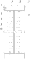
Fig. 1 is the longitudinal section sketch map of the embodiment of the invention 1 first execution mode;
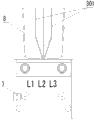
Fig. 2 is the vertical view of the embodiment of the invention 1 first execution mode;
Fig. 3 is the longitudinal section sketch map of the embodiment of the invention 1 second execution mode;
Fig. 4 is the vertical view of the embodiment of the invention 1 second execution mode;
Fig. 5 is the longitudinal section sketch map of the embodiment of the invention 1 the 3rd execution mode;
Fig. 6 is the vertical view of the embodiment of the invention 1 the 3rd execution mode;
Fig. 7 is the longitudinal section sketch map of the embodiment of the invention 1 the 4th execution mode;
Fig. 8 is the vertical view of the embodiment of the invention 1 the 4th execution mode;
Fig. 9 is the longitudinal section sketch map of the embodiment of the invention 2 first execution modes;
Figure 10 is the vertical view of the embodiment of the invention 2 first execution modes;
Figure 11 is the longitudinal section sketch map of the embodiment of the invention 2 second execution modes;
Figure 12 is the vertical view of the embodiment of the invention 2 second execution modes;
Figure 13 is the longitudinal section sketch map of the embodiment of the invention 2 the 3rd execution mode;
Figure 14 is the vertical view of the embodiment of the invention 2 the 3rd execution mode;
Figure 15 is the longitudinal section sketch map of the embodiment of the invention 2 the 4th execution mode;
Figure 16 is the vertical view of the embodiment of the invention 2 the 4th execution mode;
Figure 17 is the longitudinal section sketch map of the embodiment of the invention 3 first execution modes;
Figure 18 is the vertical view of the embodiment of the invention 3 first execution modes;
Figure 19 is the longitudinal section sketch map of the embodiment of the invention 3 second execution modes;
Figure 20 is the vertical view of the embodiment of the invention 3 second execution modes;
Figure 21 is the longitudinal section sketch map of the embodiment of the invention 3 the 3rd execution mode;
Figure 22 is the vertical view of the embodiment of the invention 3 the 3rd execution mode;
Figure 23 is the longitudinal section sketch map of the embodiment of the invention 3 the 4th execution mode;
Figure 24 is the vertical view of the embodiment of the invention 3 the 4th execution mode;
Figure 25 is the longitudinal section sketch map of the embodiment of the invention 4 first execution modes;
Figure 26 is the vertical view of the embodiment of the invention 4 first execution modes;
Figure 27 is the longitudinal section sketch map of the embodiment of the invention 4 second execution modes;
Figure 28 is the vertical view of the embodiment of the invention 4 second execution modes;
Figure 29 is the longitudinal section sketch map of the embodiment of the invention 4 the 3rd execution mode;
Figure 30 is the vertical view of the embodiment of the invention 4 the 3rd execution mode;
Figure 31 is the longitudinal section sketch map of the embodiment of the invention 4 the 4th execution mode;
Figure 32 is the vertical view of the embodiment of the invention 4 the 4th execution mode.
Embodiment
Fig. 1-shown in Figure 2 is first execution mode of embodiments of the invention 1; It is the bus duct device with three-phase three-wire system of three phase conductors (L) and grounding nut; It comprises a bus duct unit; This bus duct unit comprises a conductor layer, and this conductor layer comprises housing, phase conductor 301 that magnesium alloy processes, attaches side plate 8.
Wherein, housing is used to install phase conductor 301, and it comprises a pair of cover plate 1 and pair of side plates 2; Side plate 2 is provided with many for example five fin 5 in the both sides that deviate from phase conductor 301, be equipped with strip projected parts on every fin 5.Two pairs of adjacent fin 5 extend fixing flange 6 relatively up and down, form a chute, and promptly whole bus duct device has four chutes.Housing is provided with grounding nut 7.
Each phase conductor 301 comprises a slice copper electric conductor 9, promptly every phase monolithic copper electric conductor.Phase conductor 301 is installed in the space that cover plate 1 and side plate 2 impale, and comprises three copper electric conductors 9 altogether, is provided with insulating barrier 4 between the adjacent copper electric conductor 9, and the thickness of copper electric conductor 9 is 2 millimeters.The part of phase conductor 301 is positioned at outside the space that cover plate 1 and side plate 2 impale, and is divergent shape, and it is protected by attaching side plate 8, attaches side plate 8 and is fixedly connected on the housing.
Fig. 3-shown in Figure 4 is second execution mode of embodiment 1, and it comprises a conductor layer, and each phase conductor 301 in the conductor layer comprises two copper electric conductors 9, promptly every phase biplate copper electric conductor, and the thickness of every copper electric conductor 9 is 0.4 millimeter.
Fig. 5-shown in Figure 6 is the 3rd execution mode of embodiment 1, and it comprises two conductor layers, and a conductor layer is stacked on another conductor layer, is provided with median septum 10 between these two conductor layers; Wherein each phase conductor 301 in each conductor layer comprises a slice copper electric conductor 9, promptly every phase monolithic copper electric conductor, and the thickness of copper electric conductor 9 is 1.8 millimeters.
Fig. 7-shown in Figure 8 is the 4th execution mode of embodiment 1, and it comprises two conductor layers, and a conductor layer is stacked on another conductor layer, is provided with median septum 10 between these two conductor layers; Wherein each phase conductor 301 in each conductor layer comprises two copper electric conductors 9, promptly every phase biplate copper electric conductor, and the thickness of every copper electric conductor 9 is 0.6 millimeter.
Fig. 9-shown in Figure 10 is first execution mode of embodiments of the invention 2; It is the bus duct device with three-phase four-wire system of 301, neutral conductors of three phase conductors (L) (N) 302 and grounding nut 7; It comprises a bus duct unit; This bus duct unit comprises a conductor layer, and this conductor layer comprises housing, phase conductor 301, neutral conductor 302 that magnesium alloy processes, attaches side plate 8.
Wherein, housing is used to install phase conductor 301 and neutral conductor 302, and it comprises a pair of cover plate 1 and pair of side plates 2; Side plate 2 is provided with many for example five fin 5 in the both sides that deviate from phase conductor 301 and neutral conductor 302, is equipped with strip projected parts on every fin 5.Two pairs of adjacent fin 5 extend fixing flange 6 relatively up and down, form a chute, and promptly whole bus duct device has four chutes.Housing is provided with grounding nut 7.
Each phase conductor 301 includes a slice copper electric conductor 9, promptly every phase monolithic copper electric conductor with each neutral conductor 302.Phase conductor 301 and neutral conductor 302 are installed in the space that cover plate 1 and side plate 2 impale, and comprise four copper electric conductors 9 altogether, are provided with insulating barrier 4 between the adjacent copper electric conductor 9, and the thickness of copper electric conductor 9 is 1.9 millimeters.The part of the part of phase conductor 301 and neutral conductor 302 is positioned at outside the space that cover plate 1 and side plate 2 impale, and is divergent shape, and it is protected by attaching side plate 8, attaches side plate 8 and is fixedly connected on the housing.
Figure 11-shown in Figure 12 is second execution mode of embodiment 2; It comprises a conductor layer; Each phase conductor 301 in the conductor layer includes two copper electric conductors 9 with each neutral conductor 302, promptly every phase biplate copper electric conductor, and the thickness of every copper electric conductor 9 is 0.5 millimeter.
Figure 13-shown in Figure 14 is the 3rd execution mode of embodiment 2, and it comprises two conductor layers, and a conductor layer is stacked on another conductor layer, is provided with median septum 10 between these two conductor layers; Wherein each phase conductor 301 in each conductor layer includes a slice copper electric conductor 9 with each neutral conductor 302, promptly every phase monolithic copper electric conductor, and the thickness of copper electric conductor 9 is 1.7 millimeters.
Figure 15-shown in Figure 16 is the 4th execution mode of embodiment 2, and it comprises two conductor layers, and a conductor layer is stacked on another conductor layer, is provided with median septum 10 between these two conductor layers; Wherein each phase conductor 301 in each conductor layer includes two copper electric conductors 9 with each neutral conductor 302, promptly every phase biplate copper electric conductor, and the thickness of every copper electric conductor 9 is 0.7 millimeter.
Embodiment 3
Figure 17-shown in Figure 180 is first execution mode of embodiments of the invention 3; It is the bus duct device with three-phase five-wire mode of 301, neutral conductors of three phase conductors (L) (N) 302, housing double as earthing conductor (PE); It comprises a bus duct unit; This bus duct unit comprises a conductor layer, and this conductor layer comprises housing, phase conductor 301, neutral conductor 302 that magnesium alloy processes, attaches side plate 8.
Wherein, housing is used to install phase conductor 301 and neutral conductor 302, and it comprises a pair of cover plate 1 and pair of side plates 2; Side plate 2 is provided with many for example five fin 5 in the both sides that deviate from phase conductor 301 and neutral conductor 302, is equipped with strip projected parts on every fin 5.Two pairs of adjacent fin 5 extend fixing flange 6 relatively up and down, form a chute, and promptly whole bus duct device has four chutes.
Each phase conductor 301 includes a slice copper electric conductor 9, promptly every phase monolithic copper electric conductor with each neutral conductor 302.Phase conductor 301 and neutral conductor 302 are installed in the space that cover plate 1 and side plate 2 impale, and comprise four copper electric conductors 9, are provided with insulating barrier 4 between the adjacent copper electric conductor 9, and the thickness of copper electric conductor 9 is 1.6 millimeters.The part of the part of phase conductor 301 and neutral conductor 302 is positioned at outside the space that cover plate 1 and side plate 2 impale, and is divergent shape, and it is protected by attaching side plate 8, attaches side plate 8 and is fixedly connected on the housing.
Figure 19-shown in Figure 20 is second execution mode of embodiment 3; It comprises a conductor layer; Each phase conductor 301 in the conductor layer includes two copper electric conductors 9 with each neutral conductor 302, promptly every phase biplate copper electric conductor, and the thickness of every copper electric conductor 9 is 0.8 millimeter.
Figure 21-shown in Figure 22 is the 3rd execution mode of embodiment 3, and it comprises two conductor layers, and a conductor layer is stacked on another conductor layer, is provided with median septum 10 between these two conductor layers; Wherein each phase conductor 301 in each conductor layer includes a slice copper electric conductor 9 with each neutral conductor 302, promptly every phase monolithic copper electric conductor, and the thickness of copper electric conductor 9 is 1.4 millimeters.
Figure 23-shown in Figure 24 is the 4th execution mode of embodiment 3, and it comprises two conductor layers, and a conductor layer is stacked on another conductor layer, is provided with median septum 10 between these two conductor layers; Wherein each phase conductor 301 in each conductor layer includes two copper electric conductors 9 with each neutral conductor 302, promptly every phase biplate copper electric conductor, and the thickness of every copper electric conductor 9 is 1.0 millimeters.
Figure 25-shown in Figure 26 is first execution mode of embodiments of the invention 4; It is the bus duct device with three-phase five-wire mode of 302, earthing conductors of 301, neutral conductors of three phase conductors (L) (N) (PE) 303; It comprises a bus duct unit; This bus duct unit comprises a conductor layer, and this conductor layer comprises housing, phase conductor 301, neutral conductor 302, earthing conductor 303 that magnesium alloy processes, attaches side plate 8.
Wherein, housing is used to install phase conductor 301, neutral conductor 302 and earthing conductor 303, and it comprises a pair of cover plate 1 and pair of side plates 2; Side plate 2 is provided with many for example five fin 5 in the both sides that deviate from phase conductor 301, neutral conductor 302 and earthing conductor 303, be equipped with strip projected parts on every fin 5.Two pairs of adjacent fin 5 extend fixing flange 6 relatively up and down, form a chute, and promptly whole bus duct device has four chutes.
Each phase conductor 301, neutral conductor 302 and earthing conductor 303 include a slice copper electric conductor 9, promptly every phase monolithic copper electric conductor.Phase conductor 301, neutral conductor 302 and earthing conductor 303 are installed in the space that cover plate 1 and side plate 2 impale, and comprise five copper electric conductors 9, are provided with insulating barrier 4 between the adjacent copper electric conductor 9, and the thickness of copper electric conductor 9 is 1.5 millimeters.The part of the part of the part of phase conductor 301, neutral conductor 302, earthing conductor 303 is positioned at outside the space that cover plate 1 and side plate 2 impale, and is divergent shape, and it is protected by attaching side plate 8, attaches side plate 8 and is fixedly connected on the housing.
Figure 27-shown in Figure 28 is second execution mode of embodiment 4, and it comprises a conductor layer, and each phase conductor 301 in the conductor layer includes two copper electric conductors 9, promptly every phase biplate copper electric conductor with each neutral conductor 302; Earthing conductor in the conductor layer comprises a slice copper electric conductor; The thickness of every copper electric conductor 9 is 0.9 millimeter.
Figure 29-shown in Figure 30 is the 3rd execution mode of embodiment 4, and it comprises two conductor layers, and a conductor layer is stacked on another conductor layer, is provided with median septum 10 between these two conductor layers; Wherein each phase conductor 301, each neutral conductor 302, each earthing conductor 303 in each conductor layer includes a slice copper electric conductor 9, promptly every phase monolithic copper electric conductor, and the thickness of every copper electric conductor 9 is 1.3 millimeters.
Figure 31-shown in Figure 32 is the 4th execution mode of embodiment 4, and it comprises two conductor layers, and a conductor layer is stacked on another conductor layer, is provided with median septum 10 between these two conductor layers; Wherein each phase conductor 301 in each conductor layer includes two copper electric conductors 9, promptly every phase biplate copper electric conductor with each neutral conductor 302; Earthing conductor 303 in each conductor layer comprises a slice copper electric conductor; The thickness of every copper electric conductor 9 is 1.1 millimeters.
Though the present invention discloses as above with preferred embodiment, be not in order to limit the scope that the present invention implements.Any those of ordinary skill in the art, promptly every when doing a little improvement in not breaking away from invention scope of the present invention according to the equal improvement that the present invention did, should be invention scope of the present invention and contain.
Claims (10)
1. bus duct device, it comprises at least one bus duct unit, each said bus duct unit comprises at least one conductor layer; Each said conductor layer comprises at least one phase conductor, mutually insulated between the adjacent phase conductor; Wherein, each said phase conductor comprises the electric conductor of a slice at least, and every said electric conductor is the copper electric conductor, and its thickness is between the 0.4-2 millimeter.
2. bus duct device as claimed in claim 1, wherein, each said bus duct unit comprises a conductor layer.
3. bus duct device as claimed in claim 1, wherein, each said bus duct unit comprises two or three conductor layers, is provided with median septum between the adjacent conductor layer.
4. bus duct device as claimed in claim 1, wherein, each said conductor layer comprises three, four or five phase conductors.
5. bus duct device as claimed in claim 1, wherein, each said phase conductor comprises the electric conductor more than two or two.
6. bus duct device as claimed in claim 5 wherein, is a mutually insulated between two described electric conductors.
7. bus duct device as claimed in claim 1, wherein, each said conductor layer comprises the housing that is used to install said phase conductor, said housing comprises cover plate and at least one pair of side plate.
8. bus duct device as claimed in claim 1, wherein, at least one said side plate is provided with two or two above fin in a side that deviates from said phase conductor.
9. bus duct device as claimed in claim 8, wherein, at least one pair of the adjacent fin in the described fin extends the fixing flange relatively, forms a chute.
10. bus duct device as claimed in claim 7, wherein, said housing is that magnesium alloy is processed.
Priority Applications (1)
| Application Number | Priority Date | Filing Date | Title |
|---|---|---|---|
| CN2011102892118A CN102354936A (en) | 2011-09-26 | 2011-09-26 | Economic bus duct of copper conductor |
Applications Claiming Priority (1)
| Application Number | Priority Date | Filing Date | Title |
|---|---|---|---|
| CN2011102892118A CN102354936A (en) | 2011-09-26 | 2011-09-26 | Economic bus duct of copper conductor |
Publications (1)
| Publication Number | Publication Date |
|---|---|
| CN102354936A true CN102354936A (en) | 2012-02-15 |
Family
ID=45578460
Family Applications (1)
| Application Number | Title | Priority Date | Filing Date |
|---|---|---|---|
| CN2011102892118A Pending CN102354936A (en) | 2011-09-26 | 2011-09-26 | Economic bus duct of copper conductor |
Country Status (1)
| Country | Link |
|---|---|
| CN (1) | CN102354936A (en) |
Cited By (3)
| Publication number | Priority date | Publication date | Assignee | Title |
|---|---|---|---|---|
| CN104538913A (en) * | 2015-01-20 | 2015-04-22 | 江苏万奇电器集团有限公司 | Bus duct for in-phase two-way parallel conductor |
| CN104538755A (en) * | 2015-01-20 | 2015-04-22 | 江苏万奇电器集团有限公司 | Two-phase insulating double plugging piece of in-phase two-way parallel transition conductors |
| CN110784058A (en) * | 2018-07-24 | 2020-02-11 | 本田技研工业株式会社 | Bus bar unit |
Citations (5)
| Publication number | Priority date | Publication date | Assignee | Title |
|---|---|---|---|---|
| CN2772082Y (en) * | 2004-11-23 | 2006-04-12 | 珠海经济特区光乐电控设备厂 | High current-carrying bus duct |
| CN101473504A (en) * | 2006-04-24 | 2009-07-01 | 刘斪博 | Multiple-run bus duct system |
| CN101567536A (en) * | 2009-05-26 | 2009-10-28 | 江苏省电力公司昆山市供电公司 | Insulated fireproof bus duct |
| CN201781246U (en) * | 2010-09-09 | 2011-03-30 | 泰豪科技(深圳)电力技术有限公司 | Bus duct casing and bus duct sealing structure |
| CN202308971U (en) * | 2011-09-26 | 2012-07-04 | 珠海光乐电力母线槽有限公司 | Copper-conductor economical busway |
-
2011
- 2011-09-26 CN CN2011102892118A patent/CN102354936A/en active Pending
Patent Citations (5)
| Publication number | Priority date | Publication date | Assignee | Title |
|---|---|---|---|---|
| CN2772082Y (en) * | 2004-11-23 | 2006-04-12 | 珠海经济特区光乐电控设备厂 | High current-carrying bus duct |
| CN101473504A (en) * | 2006-04-24 | 2009-07-01 | 刘斪博 | Multiple-run bus duct system |
| CN101567536A (en) * | 2009-05-26 | 2009-10-28 | 江苏省电力公司昆山市供电公司 | Insulated fireproof bus duct |
| CN201781246U (en) * | 2010-09-09 | 2011-03-30 | 泰豪科技(深圳)电力技术有限公司 | Bus duct casing and bus duct sealing structure |
| CN202308971U (en) * | 2011-09-26 | 2012-07-04 | 珠海光乐电力母线槽有限公司 | Copper-conductor economical busway |
Cited By (4)
| Publication number | Priority date | Publication date | Assignee | Title |
|---|---|---|---|---|
| CN104538913A (en) * | 2015-01-20 | 2015-04-22 | 江苏万奇电器集团有限公司 | Bus duct for in-phase two-way parallel conductor |
| CN104538755A (en) * | 2015-01-20 | 2015-04-22 | 江苏万奇电器集团有限公司 | Two-phase insulating double plugging piece of in-phase two-way parallel transition conductors |
| CN110784058A (en) * | 2018-07-24 | 2020-02-11 | 本田技研工业株式会社 | Bus bar unit |
| CN110784058B (en) * | 2018-07-24 | 2021-12-24 | 本田技研工业株式会社 | Bus bar unit |
Similar Documents
| Publication | Publication Date | Title |
|---|---|---|
| CN202260333U (en) | Low-voltage bus way with aluminum alloy shell | |
| CN102354936A (en) | Economic bus duct of copper conductor | |
| CN202308971U (en) | Copper-conductor economical busway | |
| CN215221666U (en) | Heat radiating fin and heat radiating teeth thereof | |
| CN208257346U (en) | The high current-carrying bus duct of dynamic and thermal stability type low energy consumption | |
| CN202034736U (en) | Intensive bus groove used for transmission and distribution of electric power | |
| CN207611781U (en) | Photovoltaic module | |
| CN207251140U (en) | Special bus duct for wind power beginning unit transfer box | |
| CN207021905U (en) | Suitable for the traction inversion copped wave composite bus bar of high current | |
| CN202550291U (en) | Contactor module and photovoltaic grid connection inversion device | |
| CN202183579U (en) | Multilayer dense insulation type bus duct | |
| CN104538913A (en) | Bus duct for in-phase two-way parallel conductor | |
| CN202110870U (en) | Seven segmentation conductor of cross section with an area of 3500 mm2 of cable copper core | |
| CN102231501B (en) | Bus bar for low-voltage power distribution cabinet | |
| CN101308999A (en) | Compact bus slot | |
| CN204316048U (en) | A kind of bus duct of homophase two-way parallel conductor | |
| CN207967866U (en) | A kind of air-insulated type enclosed busbar slot | |
| CN209472560U (en) | A kind of seperated composite bus bar suitable for diesel locomotive power module | |
| CN217334994U (en) | Radiating fin of bus duct | |
| CN206774688U (en) | Integrated busbar joint | |
| CN201478764U (en) | Novel inner-cooling type all-insulation shielding metal tube bus bar | |
| CN202798009U (en) | Low voltage ride through thyristor high-speed switch valve group | |
| CN204316047U (en) | The bus duct joint device of a kind of homophase four tunnel transition conductor in parallel | |
| CN201639231U (en) | Energy-saving bus duct | |
| CN205509239U (en) | Low voltage switchgear panel |
Legal Events
| Date | Code | Title | Description |
|---|---|---|---|
| C06 | Publication | ||
| PB01 | Publication | ||
| C10 | Entry into substantive examination | ||
| SE01 | Entry into force of request for substantive examination | ||
| C02 | Deemed withdrawal of patent application after publication (patent law 2001) | ||
| WD01 | Invention patent application deemed withdrawn after publication |
Application publication date: 20120215 |