CN102275174A - Electric razor - Google Patents
Electric razor Download PDFInfo
- Publication number
- CN102275174A CN102275174A CN2011101119048A CN201110111904A CN102275174A CN 102275174 A CN102275174 A CN 102275174A CN 2011101119048 A CN2011101119048 A CN 2011101119048A CN 201110111904 A CN201110111904 A CN 201110111904A CN 102275174 A CN102275174 A CN 102275174A
- Authority
- CN
- China
- Prior art keywords
- tool unit
- cutoff tool
- inner edge
- tiltedly
- moving
- Prior art date
- Legal status (The legal status is an assumption and is not a legal conclusion. Google has not performed a legal analysis and makes no representation as to the accuracy of the status listed.)
- Pending
Links
Images


Classifications
-
- B—PERFORMING OPERATIONS; TRANSPORTING
- B26—HAND CUTTING TOOLS; CUTTING; SEVERING
- B26B—HAND-HELD CUTTING TOOLS NOT OTHERWISE PROVIDED FOR
- B26B19/00—Clippers or shavers operating with a plurality of cutting edges, e.g. hair clippers, dry shavers
- B26B19/14—Clippers or shavers operating with a plurality of cutting edges, e.g. hair clippers, dry shavers of the rotary-cutter type; Cutting heads therefor; Cutters therefor
- B26B19/16—Clippers or shavers operating with a plurality of cutting edges, e.g. hair clippers, dry shavers of the rotary-cutter type; Cutting heads therefor; Cutters therefor involving a knife cylinder or a knife cone or separate cutting elements moved like a rotating cylinder or a rotating cone
-
- B—PERFORMING OPERATIONS; TRANSPORTING
- B26—HAND CUTTING TOOLS; CUTTING; SEVERING
- B26B—HAND-HELD CUTTING TOOLS NOT OTHERWISE PROVIDED FOR
- B26B19/00—Clippers or shavers operating with a plurality of cutting edges, e.g. hair clippers, dry shavers
- B26B19/14—Clippers or shavers operating with a plurality of cutting edges, e.g. hair clippers, dry shavers of the rotary-cutter type; Cutting heads therefor; Cutters therefor
- B26B19/145—Cutters being movable in the cutting head
-
- B—PERFORMING OPERATIONS; TRANSPORTING
- B26—HAND CUTTING TOOLS; CUTTING; SEVERING
- B26B—HAND-HELD CUTTING TOOLS NOT OTHERWISE PROVIDED FOR
- B26B19/00—Clippers or shavers operating with a plurality of cutting edges, e.g. hair clippers, dry shavers
- B26B19/38—Details of, or accessories for, hair clippers, or dry shavers, e.g. housings, casings, grips, guards
- B26B19/3806—Accessories
- B26B19/382—Built-in accessories
-
- B—PERFORMING OPERATIONS; TRANSPORTING
- B26—HAND CUTTING TOOLS; CUTTING; SEVERING
- B26B—HAND-HELD CUTTING TOOLS NOT OTHERWISE PROVIDED FOR
- B26B19/00—Clippers or shavers operating with a plurality of cutting edges, e.g. hair clippers, dry shavers
- B26B19/38—Details of, or accessories for, hair clippers, or dry shavers, e.g. housings, casings, grips, guards
- B26B19/3886—Actuating members, e.g. switches or control knobs
Abstract
The invention provides an electric razor which can make a cutting unit to follow the surface of skin to move in an inclined manner by utilizing a small counter force of the skin. And the cutting unit moving in the inclined manner can be used to stretch the surface of the skin to make beard to stand up, so as to make convenience for shaving. A first and a second cutting unit (11, 12) are disposed in front and at back of the razor head (2). The first cutting unit (11) includes an outer blade (23), an inner blade (24), and an inclined frame (25). The rotation power of a motor (15) is transmitted to the inner blade (24) through a gear transmission structure. The inner blade is arranged on either of the front and the rear side in the upper half part of a sun gear wheel (60). The inner blade is driven to rotate by the solar wheel. The inclined frame surrounds a central shaft corresponding to the axes of the sun gear and can move in an inclined manner. The cutting unit moves to a standby position and exerts forces by utilizing a return spring (26). The skin surface between two cutting units is stretched through an inclined moving motion, so as to make the beard stand up.
Description
Technical field
The present invention relates to possess the rotary electric shaver that can tiltedly move the cutoff tool of displacement around a swing.
Background technology
In rotary electric shaver, known for example (have the electric shaver that makes cutoff tool tiltedly move displacement on one side on one side around a swing at patent documentation 1 in the Japanese kokai publication hei 09-038351 communique (the 0031st section, Figure 11)).Wherein, give a pair of inner edge in front and back of being located at razor head by gear transmission structure with the rotary power transmission of motor.The central shaft that razor head is supported for the extreme gear of gear transmission structure is that oscillation center can be at the head that rocks back and forth, and the variation that can follow skin surface makes the tiltedly moving displacement of front and back cutoff tool.In addition, utilize the unsteady frame of elastically deformable and compression coil spring with motor and razor head integrated support for can be in the displacement that fluctuates.
At patent documentation 2 ((the 0016th section in Japanese kokai publication hei 07-112080 communique, in rotary electric shaver Fig. 1)), utilization moves up and down a side of bearings inner edge freely, utilize two friction rolls to prop up the friction roll that stays at other end side, and inner edge is supported for the displacement of can falling.In detail, central gear and planetary gear are set, give inner edge with planetary rotary power transmission by friction roll in the terminal of the gear transmission structure of drive motor power.The friction roll of driving side is fixed on the planet pin, and the friction roll of slave end is fixed on the inner edge axle.Be not provided with on consubstantiality ground with the external auxiliary friction roll of the friction roll of slave end and these friction rolls, its Roller Shaft to be can guiding at shell wall with respect to the mode that the friction roll contact separation of slave end is slided, and utilizes spring-loaded and approaching.The displacement of falling while the interval between friction roll that enlarges driving side and the auxiliary friction roll of the friction roll of inner edge side.The displacement of the inner edge of this occasion is not correctly to move displacement around the oblique of a swing, but approximate displacement action.
In the electric shaver of patent documentation 1, the variation that can follow skin surface makes the tiltedly moving displacement of front and back cutoff tool.But, owing to make the swing of shaking the head in front and back of razor head integral body, therefore if not certain above reaction force from skin surface (being designated hereinafter simply as the skin reaction force) is applied to the situation on the cutoff tool, then can't make the tiltedly moving displacement of razor head, excessive with contacting of skin when shaving, the tiltedly moving action when cutoff tool is followed the variation of skin surface slows up easily.
In addition, in the electric shaver of patent documentation 2, move up and down a side of the bearings inner edge of resiliency supported freely owing to utilize, utilize two friction rolls to support another side, therefore be difficult to make bearing and two friction rolls to fall equably, can't make outside and inner edge driving fit sometimes.Therefore, Yi Bian tiltedly move the occasion of shaving on one side, the cutting performance of blade descends easily.
Summary of the invention
The object of the present invention is to provide a kind of electric shaver, can either make the tiltedly moving displacement in cutoff tool unit can follow the variation of skin surface again, therefore, can shave easily with littler skin reaction force.
The object of the present invention is to provide a kind of electric shaver, can utilize tiltedly moving cutoff tool unit stretching skin surface and beard is erected, therefore, can shave effectively.
With regard to electric shaver of the present invention, the cutoff tool unit of being located on the razor head 2 11 possesses outside 23, rotary inner edge 24, reaches and support the two tiltedly moving framework 25 of 23,24.Between motor 15 and inner edge 24, be provided with the drive mechanism of the rotary power transmission of motor 15 being given inner edge.Inner edge 24 is configured in the front and back either side of the first half of the central gear 60 on the terminal of being located at drive mechanism, and is driven by central gear 60 rotations.Tiltedly moving framework 25 has the axle center consistent with the axle center of central gear 60, with position of readiness that can be up with than tiltedly moving between the tiltedly moving position of position of readiness by the below.Cutoff tool unit 11 utilizes back-moving spring 26 to move and reinforcing to position of readiness.
Razor head 2 is provided with first, second cutoff tool unit 11,12 at least in front and back.The first cutoff tool unit 11 constitutes and comprises outside 23, rotary inner edge 24, and supports the two tiltedly moving framework 25 of 23,24.The inner edge 24,40 of first, second cutoff tool unit 11,12 is configured in the front and back of the first half of central gear 60, and is driven by central gear 60 rotations.As shown in Figure 7, utilize the tiltedly action of the first cutoff tool unit 11 to enlarge the interval of two cutoff tool unit 11,12 and the stretching skin surface.
As shown in Figure 5, make the turning moment of central gear 60 and back-moving spring 26 to add force direction consistent, utilize the turning moment of central gear 60, the auxiliary first cutoff tool unit 11 utilizes the homing action of back-moving spring 26.
Razor head 2 is provided with first, second cutoff tool unit 11,12 at least in front and back.Make the diameter difference of the inner edge 24,40 of first, second cutoff tool unit 11,12.
The peripheral speed of the inner edge 24 that diameter is little is set identically or littler than the peripheral speed of inner edge 40 with the peripheral speed of the big inner edge 40 of diameter.The driving rotating speed that the driving speed setting of the inner edge 40 that diameter is big gets the little inner edge of diameter group 24 is little.
Razor head 2 is provided with first, second cutoff tool unit 11,12 at least in front and back.Make the diameter difference of the inner edge 24,40 of first, second cutoff tool unit 11,12.Tiltedly moving the first cutoff tool unit 11 that possesses the little inner edge of diameter 24 can be supported for around the axle center consistent with the axle center of central gear 60.In this occasion, the second cutoff tool unit 12 can be any in the structure that can't fluctuate and the structure that can fluctuate, but in the latter's occasion, sets the spring pressure of floating spring 21 bigger than the spring pressure of back-moving spring 71.
Between first, second cutoff tool unit 11,12, be provided with the outside 46 that possesses otch sword structure and the 3rd cutoff tool unit 13 of rotary inner edge 47.By the pinion 60b that rotates with central gear 60, the inner edge 47 that reaches inner edge gear 63 rotation drivings the 3rd cutoff tool unit 13.
As shown in Figure 3, the main part 1 by the double as handle can support razor head 2 by floating structure with fluctuating.Thus, the first cutoff tool unit 11 can be with respect to razor head 2 tiltedly moving displacements, and razor head 2 can fluctuate with respect to main part 1.
Floating structure possesses the floating spring 21 that boosts razor head 2 and reinforcing.Set the elastic force of the back-moving spring 26 of the first cutoff tool unit 11 littler than the elastic force of the floating spring 21 of floating structure.
Make the top of the first cutoff tool unit 11 that is positioned at position of readiness be positioned at top than the second cutoff tool unit 12 by the top.Thus, when shaving, can make the first cutoff tool unit 11 tiltedly moving before other cutoff tool unit 12,13.
Effect of the present invention is as follows.
In the present invention, utilize tiltedly moving framework 25 to support outsides 23 and inner edge 24 and constitute cutoff tool unit 11,, thereby can utilize central gear 60 rotations to drive the inner edge 24 of tiltedly moving displacement around the axle supporting tiltedly moving framework 25 in axle center consistent with the axle center of central gear 60.In addition, can utilize back-moving spring 26 to make cutoff tool unit 11 automatically reset to position of readiness.So, if the cutoff tool unit 11 that can tiltedly move independently is set on razor head 2, then compare with making the whole tiltedly moving existing electric shaver of razor head, the 11 tiltedly moving displacements of cutoff tool unit can be made with littler skin reaction force, and the variation of skin surface can be followed sleekly.Therefore, can shave easily.
As if the front and back that first, second cutoff tool unit 11,12 are configured in the first half of central gear 60, the oblique kinetic moment around the axle center consistent with the axle center of central gear 60 of utilizing deadweight to produce is always acted on the first cutoff tool unit 11 that can support tiltedly movingly.If the first cutoff tool unit 11 that is positioned at position of readiness utilizes the elastic force of back-moving spring 26 to overcome above-mentioned oblique kinetic moment and the holding position, but the skin reaction force acts, then overcomes the elastic force of back-moving spring 26 and tiltedly moving displacement.The oblique kinetic moment of the first cutoff tool unit 11 of this moment is followed from the increase of the oblique angle of moving of position of readiness to be increased.This is that the arm of force of the first cutoff tool unit 11 is big more because tiltedly moving angle increases more.Therefore, can utilize the increase of oblique kinetic moment to reduce the increase of back-moving spring 26 elastic force when tiltedly moving in the first cutoff tool unit 11, reduce the skin reaction force in the tiltedly moving process in the first cutoff tool unit 11, thereby can make the 11 tiltedly moving displacements of cutoff tool unit with littler skin reaction force.In addition, the degree that the skin reaction force when shaving reduces correspondingly reduces the stimulation to skin surface, thereby can shave easily.
Owing to first, second cutoff tool unit 11,12 is configured in the front and back of central gear 60, and make the first cutoff tool unit 11 tiltedly moving around the axle center consistent with the axle center of central gear 60, when therefore tiltedly moving in the first cutoff tool unit 11, the interval of two cutoff tool unit 11,12 can be enlarged, thereby skin surface can be stretched.In detail, to tiltedly moving away from the direction of the second cutoff tool unit 12, at this moment, the skin surface of 11,12 of the two cutoff tool unit of stretching erects thereby can make to be poured on the frizzle on the skin surface and to become mildewed when shaving in the first cutoff tool unit 11.Therefore, any that can utilize two cutoff tool unit 11,12 shaved effectively and removed to erecting the beard of state.
If make central gear 60 turning moment direction with utilize back-moving spring 26 consistent to the direction of tiltedly moving framework 25 reinforcings, then can utilize above-mentioned turning moment to assist the homing action of the first cutoff tool unit 11 by back-moving spring 26.Thus, the reset force that can produce with the turning moment by central gear 60 correspondingly reduces the spring pressure of back-moving spring 26, therefore, can make the first cutoff tool unit 11 tiltedly moving more easily with littler power.
If make the diameter difference of inner edge 24,40 of first, second cutoff tool unit 11,12 of the front and back of being located at razor head 2, then can increase the contact area of the cutoff tool unit 12 that possesses the big inner edge of diameter 40 and skin surface, thereby can correspondingly shave effectively at short notice.In addition, with regard to the cutoff tool unit 11 that possesses the little inner edge of diameter 24, existence diminishes with the contact area of skin surface, the skin reaction force correspondingly becomes big tendency, thereby can essence shave undercoat.Therefore, utilize first, second two cutoff tools unit 11,12 slightly to shave collaboratively and essence is shaved, thereby can in the shorter time, shave effectively.
If the peripheral speed of inner edge 24 that diameter is little is set identically or littler than the peripheral speed of inner edge 40 with the peripheral speed of the big inner edge 40 of diameter, then can reduce the little sword of the little inner edge of diameter 24 and skin surface butt number of times, reach amount of friction and relax burden skin surface.In addition, in the big inner edge 40 of diameter, since big with the contact area of skin surface, therefore can shave simultaneously and remove more substantial beard, but need bigger driving torque.In order to ensure this driving torque, the driving rotating speed that the driving speed setting of the inner edge 40 that diameter is big gets the little inner edge of diameter group 24 is little.In addition, can increase with the driving torque of inner edge 40 and correspondingly effectively shave, thereby can relax burden skin surface.
As mentioned above, in possessing the first cutoff tool unit 11 of the little inner edge of diameter 24, compare the skin reaction force with another cutoff tool unit 12 and act on consumingly, skin falls into the inside of outside 23 easily.Therefore, the stimulation increase to skin has the tendency that is easy to generate tingling sensation.But, if tiltedly moving mode supports around the axle center consistent with the axle center of central gear 60 can make the first cutoff tool unit 11, then can be corresponding with the minor variations of skin reaction force, make the first cutoff tool unit 11 tiltedly moving sensitively, therefore can prevent from exceedingly to push skin surface.
Between first, second cutoff tool unit 11,12, be provided with the 3rd cutoff tool unit 13, if drive its inner edge 47 by central gear 60 and 63 rotations of inner edge gear, then utilize the gear drive of a side of being located at razor head 2 to carry out the driving of each cutoff tool unit 11~13 simultaneously.Therefore, can open the following side space of each cutoff tool unit 11~13 fully, thereby remove soft flocks more easily.For example, constitute the occasion that comprises round portable inner edge 47 in the 3rd cutoff tool unit 13, the following side space of at least the three cutoff tool unit 13 is occupied by the inner edge drives structure, can't prevent soft flocks attached to its surface, spends time in cleaning.In addition as mentioned above, the skin surface because the first tiltedly moving cutoff tool unit 11 can stretch, erect thereby make to be poured on the frizzle on the skin surface and to become mildewed, therefore can utilize the 3rd cutoff tool unit of being located between the two cutoff tool unit 11,12 13 to shave effectively and remove the beard that erects.
If the main part 1 by the double as handle can support razor head 2 with fluctuating, then can make the 11 tiltedly moving displacements of the first cutoff tool unit certainly, and razor head 2 is fluctuated with respect to main part 1.Therefore, the user can shave under the state that the first cutoff tool unit 11 is tiltedly moved, or make the first cutoff tool unit 11 tiltedly move, also shave, thereby can when shaving, diversely select pushing force to skin surface while razor head 2 is fluctuated.
If set the elastic force of the back-moving spring 26 of the first cutoff tool unit 11 littler than the elastic force of the floating spring 21 of floating structure, then, can limit fluctuating of razor head 2 up to because of the tiltedly moving spring pressure of back-moving spring 26 that causes in the first cutoff tool unit 11 surpasses setting.Therefore when shaving, can either prevent that razor head 2 from unnecessarily fluctuating, can shave reliably making under the tiltedly moving state in the first cutoff tool unit 11 again.In addition, the second cutoff tool unit 12 is being pressed against under the situation of skin surface tightly, fluctuating, preventing from exceedingly to stimulate skin surface, thereby can relax burden skin surface by making razor head 2.
If being positioned at than the top of the second cutoff tool unit 12, the top of the first cutoff tool unit 11 that is positioned at position of readiness leans on the top, then when shaving, at first make the first cutoff tool unit 11 before other cutoff tool unit 12,13, push skin surface, under the state that skin surface is extended, shave.Therefore, can utilize a plurality of cutoff tools unit 11,12,13 to shave simultaneously and remove the beard of the skin surface of utilizing 11 extensions of the first cutoff tool unit, thereby can shave operation at short notice effectively.
Description of drawings
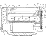
Fig. 1 is the vertical profile side view of cutoff tool of the present invention unit.
Fig. 2 is the front view of electric shaver.
Fig. 3 is the vertical profile front view of the unsteady supporting construction of expression razor head.
Fig. 4 is the vertical view of cutoff tool unit.
Fig. 5 is the vertical profile side view of expression gear transmission structure.
Fig. 6 is the exploded perspective view of the inner edge that is made of the otch sword.
Fig. 7 is the action specification figure of the state of expression cutoff tool unit when shaving.
Fig. 8 is the vertical profile side view of another embodiment of expression cutoff tool unit.
Fig. 9 is the side view of gear transmission structure of the cutoff tool unit of presentation graphs 8.
Figure 10 is the vertical profile side view of the another embodiment of expression cutoff tool unit.
Figure 11 is the vertical profile side view of the another embodiment of expression cutoff tool unit.
Figure 12 is the vertical profile front view of another embodiment of expression drive mechanism.
Among the figure:
The 1-main part, 2-razor head, 8-matrix, the 9-gear cover, 10-blade base, the 11-first cutoff tool unit, the 12-second cutoff tool unit, 13-the 3rd cutoff tool unit, 15-motor, 23,39-outside, 24, the 40-inner edge, the tiltedly moving framework of 25-, the 26-back-moving spring, the 60-central gear, 61,62-inner edge gear, the 65-central gear shaft.
The specific embodiment
(embodiment)
Fig. 1~Fig. 7 represents the embodiment of rotary electric shaver of the present invention.All around of the present invention, up and down according to the crossing arrow of Figure 1 and Figure 2 and near all around of arrow, representing, up and down mark.In Fig. 2, rotary electric shaver possesses the main part 1 of double as handle and by the main part 1 and the razor head 2 that can support by floating structure with fluctuating.Be provided with selector switch 4 that motor works the operating condition of employing shift knob 3, switching motor, and LED display part 5 in the front of main part 1.Accommodate secondary cell 6 in the inside of main part 1 and the circuit substrate etc. of the parts that constitute control circuit is installed.
As shown in Figure 3, between the inner casing 18 of the inside of motor bracket 14 and main part 1, be provided with to float and support the floating structure of razor head 2.Floating structure comprise on the relative wall of being located at inner casing 18 long up and down sliding tray 19, in sliding tray 19 by the projection 20 of the motor bracket 14 of sliding guidance and be configured in inner casing 18 and motor bracket 14 between floating spring 21 etc.So, support razor head 2 freely, when shaving,, can make razor head 2 displacement that fluctuates by acting on the skin reaction force on each cutoff tool unit 11~13 by utilizing floating structure to fluctuate.
The first cutoff tool unit (cutoff tool unit) 11 comprises outside 23, the rotary inner edge 24 that is made of the grid sword, the tiltedly moving framework 25 that supports the two and back-moving spring 26 etc., and is configured in the front portion (with reference to Fig. 1) of razor head 2.Tiltedly moving framework 25 possesses the sidewall 28 of pair of right and left, a pair of front and rear wall 29 that connects the two, and diapire 30 integratedly, and bearing portion 31 is outstanding backward on two side 28.
By utilizing central gear shaft 65 described later and oblique moving axis 66 shaft support bearing portions 31, the first cutoff tool unit 11 in Fig. 1, tiltedly to move with the position of readiness shown in the solid line with tiltedly moving between the position shown in the dotted line.In order to make tiltedly moving framework 25 so that more stable status is tiltedly moving, utilize on the outstanding outer surface of being located at sidewall 28 of guiding groove 33 guiding on the left and right sides sidewall of being located at blade base 10 rocking pin 32 and by the inner edge axle 37 of 28 supportings of sidewall.The oblique arena limit of tiltedly moving framework 25 is by rocking pin 32 and inner edge axle 37 and guiding groove 33 regulations.Tiltedly moving axis 66 is located on the central axis of central gear shaft 65, and is fixed on the left side wall of blade base 10 (with reference to Fig. 3).Back-moving spring 26 is made of helical spring, and it is fixing that the one end is accepted recess 16 by the spring of blade base 10, and it is fixing that the other end is accepted recess 34 by the spring of the diapire 30 of tiltedly moving framework 25.The elastic force of back-moving spring 26 is set at littler than the elastic force of the floating spring 21 of above-mentioned floating structure.
As shown in Figure 6, inner edge 24 is formed cylindric by three discoid stand frames 35 and three the sword main bodys 36 on every side that are fixed on stand frame 35, and inner edge axle 37 is fixed therein the heart.The sword main body 36 of otch sword structure is formed by electrocasting.As shown in Figure 3, the two ends of inner edge axle 37 rotate ground axle suspension freely by the left and right sides sidewall 28 of tiltedly moving framework 25.The lower end of the front-back of outside 23 is supported by the oblique front and rear wall 29 of moving framework 25, utilizes not shown tension construction stretch and reinforcing (with reference to Fig. 1) thus, can always remain on the outside 23 that remains arch shape the state with inner edge 24 driving fits.The first cutoff tool unit 11 is further shaved to remove and is utilized the second cutoff tool unit 12 to shave the undercoat after removing and carry out essence and shave.
The second cutoff tool unit (cutoff tool unit) 12 comprises inner edge 40, and the configuration inner edge axle 41 in the central etc. of the outside 39 that is made of the grid sword, otch bladed, and is whole with the rear portion of the state configuration parallel with the first cutoff tool unit 11 at razor head 2.The inner edge 24 of the inner edge 40 and the first cutoff tool unit 11 constitutes in the same manner, but the two ends of its inner edge axle 41 utilize the base body 10a of blade base 10 to rotate with side frame 10b that the ground axle suspension this point is different with the inner edge 24 of the first cutoff tool unit 11 freely.First, second two cutoff tools unit 11,12 constitutes and is mainly used in the cutoff tool unit of shaving except that undercoat.
That is to say that the second cutoff tool unit 12 can fluctuate with razor head 2, but can't tiltedly move separately or fluctuate separately.In addition, the diameter dimension of the inner edge 40 of the second cutoff tool unit 12 is set greatlyyer than the diameter of the inner edge 24 of the first cutoff tool unit 11.The lower end of the front-back of outside 39 is supported by median wall on the base body 10a that is located at blade base 10 43 and rear wall 44, utilize not shown tension construction stretch and reinforcing, thus, can always the outside 39 that remains arch shape be remained on state with inner edge 40 driving fits.The second cutoff tool unit 12 is mainly used in slightly shaves undercoat.
As mentioned above, if make littler than the diameter of the inner edge 40 of the second cutoff tool unit 12, the then a large amount of second big cutoff tool unit 12 of beard importing surface area of diameter of the inner edge 24 of the first cutoff tool unit 11, can shave effectively at short notice.Because the first cutoff tool unit 11 is little with the diameter that inner edge 24 is compared in the second cutoff tool unit 12, like this, pressure is applied on the skin surface easily.Therefore, compare with other cutoff tool unit 12,13, the skin reaction force acts on consumingly, and skin falls into the inside of outside 23 easily, and the tendency of the stimulation increase of pair skin is arranged.Be easy to generate tingling sensation.In order to relax this stimulation, and can support the first cutoff tool unit 11 tiltedly movingly, prevent that excessive pressure from acting on the skin surface skin surface.
As shown in Figure 1, size H is given prominence to upward than the top of the second cutoff tool unit 12 in the top that is positioned at the first cutoff tool unit 11 of position of readiness.And,, the oblique kinetic moment that is produced by gravity is always acted on the first cutoff tool unit 11 owing to make the inner edge 24 of the first cutoff tool unit 11 be positioned at the top in oblique the place ahead of central gear shaft 65.Therefore, when shaving, the first cutoff tool unit 11 was contacted before other cutoff tool unit 12,13 with skin surface, and make the tiltedly moving and oblique easily corresponding degree of kinetic moment in the first cutoff tool unit 11.
Therefore, from the tiltedly moving occasion of position of readiness, because the arm of force follows the increase of tiltedly moving angle to increase, therefore oblique kinetic moment increases corresponding degree in the first cutoff tool unit 11.Therefore, can reduce the increase of the elastic force of back-moving spring 26 when the first cutoff tool unit, 11 oblique moving by the increase of oblique kinetic moment, reduce the skin reaction force in the first cutoff tool unit, the 11 tiltedly moving processes, thereby can make the 11 tiltedly moving displacements of cutoff tool unit with littler skin reaction force.In addition, tiltedly moving by the first cutoff tool unit 11 after the second cutoff tool unit 12 pushing skin surface as shown in Figure 7, can enlarge the interval of two cutoff tool unit 11,12 and the stretching skin surface.Therefore, can make the frizzle that is poured on skin surface and become mildewed to erect, remove the beard that erects thereby can utilize the 3rd cutoff tool unit 13 to shave effectively.
The 3rd cutoff tool unit 13 (cutoff tool unit) disposes abreast with two cutoff tool unit 11,12 between first, second two cutoff tools unit 11,12.The top of the 3rd cutoff tool unit 13 is positioned at the below than the top of the second cutoff tool unit 12.The 3rd cutoff tool unit comprises inner edge 47, and the configuration inner edge axle 48 etc. in the central of outside 46, otch bladed, uses outside 46 this point of otch sword structure different with above-mentioned cutoff tool unit 11,12.The 3rd cutoff tool unit 13 constitutes to be mainly used in to shave to remove and becomes mildewed and the cutoff tool unit of frizzle.
The diameter of inner edge 47 is set also forr a short time than the diameter of the inner edge 24 of the above-mentioned first cutoff tool unit 11.The inner edge 24 of the inner edge 47 and the first cutoff tool unit 11 constitutes in the same manner, and the ground axle suspension this point is different with the inner edge 24 of the first cutoff tool unit 11 freely but its inner edge axle 48 is rotated with side frame 10b by the base body 10a of blade base 10.The lower end of the front-back of outside 46 is supported by supplementary wall 49 and the above-mentioned median wall 43 be located on the base body 10a, utilizes not shown tension construction stretch, thus, can always the outside 46 that remains arch shape be remained on the state with inner edge 47 driving fits.The 3rd cutoff tool unit 13 mainly shave remove become mildewed, frizzle.
In Fig. 3 and Fig. 5, gear transmission structure is made of the upper surface of the matrix 8 from the beginning gear train along the outer surface configuration of the side frame of blade base 10, the rotary power of motor 15 is converted to around the rotation of the jackshaft 50 of level and each inner edge 24,40,47 is given in transmission.In detail, the 3rd gear 53 and the 4th gear 54 that constitutes by first gear 51, second gear 52, by each bevel gear given jackshaft 50 with the rotary power transmission of motor 15.In addition, give the central gear 60 of the terminal of being located at gear train with the rotary power that is fixed on the 5th gear 55 on the side of jackshaft 50 by the 6th gear 56,57 transmissions of the 7th gear.In addition, give the inner edge gear 61,62,63 that is fixed on each inner edge axle 37,41,48, and drive each inner edge 24,40,47 simultaneously and rotate the rotary power transmission of central gear 60.
The 6th gear 56 and central gear 60 possess gear wheel 56a, 60a and pinion 56b, 60b respectively integratedly, the gear wheel 56a of the 6th gear 56 and 55 engagements of the 5th gear, pinion 56b and 57 engagements of the 7th gear.The gear wheel 60a of central gear 60 simultaneously with the inner edge gear 61 of the 7th gear 57, the first cutoff tool unit 11, and inner edge gear 62 engagements of the second cutoff tool unit 12, the inner edge gear 63 of the pinion 60b of central gear 60 and the 3rd cutoff tool unit 13 meshes.
The direction of rotation of central gear 60, inner edge 61,62,63 shown in Fig. 5 arrow, make the turning moment of central gear 60 and back-moving spring 26 to add force direction consistent.Thus, utilize the turning moment of central gear 60, can assist the first cutoff tool unit 11 to utilize the homing action of back-moving spring 26, thereby correspondingly reduce the spring pressure of back-moving spring 26, can make the first cutoff tool unit 11 tiltedly moving easily with littler power.Outer surface from the 5th gear 55 to the gear train of each inner edge gear 61~63 is covered by cover 68.Similarly, the left surface of base body 10a is also by cover 68 sealings.
By adjusting the tooth ratio of a central gear 60 and an inner edge gear 61,62,63, the peripheral speed of each inner edge 24,40,47 of following setting, and drive rotating speed.Be made as 0.92m/s in peripheral speed with the inner edge 24 of the first cutoff tool unit 11, when the driving rotating speed of inner edge 24 is made as 2700rpm, the peripheral speed of the inner edge 40 of the second cutoff tool unit 12 is made as 1.2m/s, the driving rotating speed of inner edge 40 is made as 2300rpm.In addition, the peripheral speed of the inner edge 47 of the 3rd cutoff tool unit 13 is 0.63m/s, and the driving rotating speed of inner edge 47 is 2400rpm.
As mentioned above, if make the peripheral speed of inner edge 24 littler than the peripheral speed of inner edge 40, then can reduce the little sword of the little inner edge of diameter 24 and skin surface butt number of times, reach amount of friction, thereby can relax burden to skin surface.In addition, in the big inner edge 40 of diameter, since big with the contact area of skin surface, therefore can shave simultaneously and remove more substantial beard, but need bigger driving torque.In order to ensure this driving torque, the driving speed setting of the inner edge 40 that diameter is big is that the driving rotating speed of the little inner edge of diameter group 24 is little.
In the electric shaver that as above constitutes, corresponding to the diameter of the inner edge 24 of the first cutoff tool unit 11 the little part of diameter, can make the overall weight of the first cutoff tool unit 11 littler than the overall weight of the second cutoff tool unit 12 than the inner edge 40 of the second cutoff tool unit 12.Therefore, back-moving spring 26 can remain on position of readiness with the first cutoff tool unit 11 with littler spring pressure.In addition, owing to make the first cutoff tool unit 11 tiltedly moving around the axle center consistent with the axle center of central gear 60, and the inner edge 24 that makes the first cutoff tool unit 11 is positioned at the place ahead of the first half of central gear 60, and therefore the oblique kinetic moment that can utilize gravity to produce always acts on the first cutoff tool unit 11.Therefore, in use, can make the first cutoff tool unit 11 tiltedly moving easily with littler skin reaction force.In addition, can with reduce degree to the pushing force of skin and reduce stimulation accordingly skin surface.
Electric shaver can be implemented in following mode as constituted above.
The cutoff tool unit of being located on the razor head 2 11 possesses outside 23, rotary inner edge 24, reaches and support the two tiltedly moving framework 25 of 23,24.Between motor 15 and inner edge 24, be provided with the gear transmission structure of the rotary power transmission of motor 15 being given inner edge.Inner edge 24 is configured in the front and back either side of the first half of the central gear 60 of the terminal of being located at gear transmission structure, and is driven by central gear 60 rotations.Tiltedly moving framework 25 is around the axle center axle supporting consistent with the axle center of central gear 60, so that position of readiness that can be up and than tiltedly moving between the tiltedly moving position of position of readiness by the below.Cutoff tool unit 11 utilizes back-moving spring 26 to move and reinforcing to position of readiness.
The turning moment that makes central gear 60 and back-moving spring 26 to add force direction consistent, utilize the auxiliary first cutoff tool unit 11 of turning moment of central gear 60 to utilize the homing action of back-moving spring 26.
Be made as V1 in peripheral speed with the inner edge 24 of the first cutoff tool unit 11, when the peripheral speed of the inner edge 40 of the second cutoff tool unit 12 is made as V2, be set at (V1≤V2).In addition, be made as N1 at driving rotating speed with the inner edge 24 of the first cutoff tool unit 11, when the driving rotating speed of the inner edge 40 of the second cutoff tool unit 12 is made as N2, be set at (N1>N2).
Fig. 8 and Fig. 9 represent another embodiment of cutoff tool of the present invention unit.Wherein, utilize tiltedly moving framework 70 to support the second cutoff tool unit 12 in the same manner with the first cutoff tool unit 11, thus can be tiltedly moving around central gear shaft 65 and oblique moving axis 66, utilize back-moving spring 71 to reset to the position of readiness reinforcing.Dispose first, second two cutoff tools unit 11,12 in the front and back of central gear 60, because as the common tiltedly moving central shaft in two unit 11,12, therefore the second cutoff tool unit 12 tiltedly moves to the dextrorotation veer on the contrary with the first cutoff tool unit 11 with central gear shaft 65 and oblique moving axis 66.In addition, the elastic force of the back-moving spring 26 of the first cutoff tool unit 11 is set forr a short time than the elastic force of the back-moving spring 71 of the second cutoff tool unit 12, therefore, the first cutoff tool unit 11 is contacted well when shaving with skin.
Tiltedly moving framework 70 possesses the sidewall 74 of pair of right and left, a pair of front and rear wall 75 that connects the two and diapire 76 integratedly, and is outstanding forward by the bearing portion 77 that 65 of central gear shafts are bearing on the two side 74.At the oblique outstanding rocking pin 78 that is provided with of outer surface of the sidewall 74 of moving framework 70, this pin 78 and guide by the guiding groove on the left and right sides sidewall of being located at blade base 10 79 by the inner edge axle 41 of 74 supportings of sidewall.The oblique arena limit of tiltedly moving framework 70 is by rocking pin 78 and inner edge axle 41 and guiding groove 79 regulations.The drives structure of the inner edge 24 of the first cutoff tool unit 11 and the inner edge 40 of the second cutoff tool unit 12 is same as the previously described embodiments basically, but as shown in Figure 9, give internal gear 61,62 this point differences with the rotary power transmission of central gear 60 by the extreme gear 80,80 on the sidewall 28 of being located at tiltedly moving framework 25.So, the rotary power of central gear 60 can be given inner edge 61,62 by more than one extreme gear 80,80 transmissions.Because other structures are same as the previously described embodiments, therefore mark same-sign and omit its explanation in same parts.Also identical in following embodiment.
Figure 10 represents the another embodiment of cutoff tool of the present invention unit.Wherein, the first cutoff tool unit 11 is set in the front and back of razor head 2 different with the foregoing description with the round portable second cutoff tool unit 12 this point.The second cutoff tool unit 12 comprises outside 81 that is made of the otch sword and the inner edge 82 that possesses one group of little sword.In order to drive inner edge 82, with branch's gear 83 of second gear, 52 engagements on cam pin 84 is set, utilize cam pin about 84 to drive driving shafts 85, and the round power transmission that will change is to inner edge 82 toward ground returns.Branch's gear 83, cam pin 84 and driving shaft 85 constitute the action transformational structure.
Figure 11 represents the another embodiment of cutoff tool of the present invention unit.Wherein, dispose the first cutoff tool unit 11 and the second cutoff tool unit 12 in the front and back of razor head 2, configuration comes and goes portable the 3rd cutoff tool unit 13 between two cutoff tool unit 11,12.The 3rd cutoff tool unit 13 comprises the outside that is made of the otch sword 91 and possesses the inner edge 92 of one group of little sword, utilizes and in identical action transformational structure illustrated in fig. 9 rotary power is converted to round power, and utilize driving shaft 93 to come and go driving inner edges 92.The inner edge gear 62 of the second cutoff tool unit 12 is driven by the octadentate wheel 58 with 57 engagements of the 7th gear.
It is gear transmission structure that drive mechanism there is no need, can utilize flexible drive mechanism (drive mechanism) with the rotary power of motor 15 to central gear 60 transmissions.For example as shown in figure 12, respectively timing belt pulley 89,90 is fixed on the output shaft 88 and central gear shaft 65 of motor 15, coiling synchronous belts 94 on both, thus can give central gear shaft 65 with the direct transmission of motor power.
In the embodiment of Fig. 1~Fig. 7, utilize central gear shaft 65 and the oblique tiltedly moving framework 25 of 66 supportings of moving axis, but do not have that necessity, also can utilize on the central axis of central gear 60, be provided with, one or two bolster supports tiltedly moving framework 25.The bolster of this occasion can with central gear shaft 65 one, also consubstantiality not.In addition, in the left and right sides bearing portion 31 of tiltedly moving framework 25, be provided with the axle that is equivalent to above-mentioned bolster integratedly, can utilize the dead eye that is formed on side frame 10a, the 10b to support these axles.As long as tiltedly moving framework 25 is around the axle center axle supporting consistent with the axle center of central gear 60, no matter be which kind of axle support structure.
Claims (10)
1. an electric shaver is characterized in that,
The cutoff tool unit of being located on the razor head (2) (11) possesses outside (23), rotary inner edge (24), reaches the tiltedly moving framework (25) that supports the two (23,24),
Between motor (15) and inner edge (24), be provided with the drive mechanism of the rotary power transmission of motor (15) being given inner edge,
Inner edge (24) be configured in the terminal of being located at drive mechanism central gear (60) the first half the front and back either side and drive by central gear (60) rotation,
Tiltedly moving framework (25) has the consistent axle center, axle center with central gear (60), with position of readiness that can be up and than tiltedly moving between the tiltedly moving position of position of readiness by the below,
Cutoff tool unit (11) utilizes back-moving spring (26) to move and reinforcing to position of readiness.
2. electric shaver according to claim 1 is characterized in that,
Razor head (2) is provided with first, second cutoff tool unit (11,12) at least in front and back,
The first cutoff tool unit (11) comprises outside (23), rotary inner edge (24), reaches the tiltedly moving framework (25) that supports the two (23,24),
The inner edge (24,40) of first, second cutoff tool unit (11,12) be configured in central gear (60) the first half front and back and drive by central gear (60) rotation,
Utilize the tiltedly action of the first cutoff tool unit (11) to enlarge the interval of two cutoff tool unit (11,12) and the stretching skin surface.
3. electric shaver according to claim 1 and 2 is characterized in that,
The turning moment that makes central gear (60) and back-moving spring (26) to add force direction consistent, utilize the homing action that utilizes back-moving spring (26) of the auxiliary first cutoff tool unit (11) of turning moment of central gear (60).
4. according to claim 2 or 3 described electric shavers, it is characterized in that,
Razor head (2) is provided with first, second cutoff tool unit (11,12) at least in front and back,
Make the diameter difference of the inner edge (24,40) of first, second cutoff tool unit (11,12).
5. electric shaver according to claim 4 is characterized in that,
The peripheral speed of the inner edge that peripheral speed is identical or diameter group is big (40) of the inner edge (40) that the peripheral speed of the inner edge that diameter is little (24) is set greatly with diameter is little,
The driving rotating speed that the driving speed setting of the inner edge that diameter is big (40) gets the little inner edge of diameter group (24) is little.
6. according to claim 4 or 5 described electric shavers, it is characterized in that,
Razor head (2) is provided with first, second cutoff tool unit (11,12) at least in front and back,
Make the diameter difference of the inner edge (24,40) of first, second cutoff tool unit (11,12),
The first cutoff tool unit (11) that possesses the little inner edge of diameter (24) supports in the mode that can tiltedly move around the axle center consistent with the axle center of central gear (60).
7. according to each described electric shaver of claim 2~6, it is characterized in that,
Between first, second cutoff tool unit (11,12), be provided with the outside (46) that possesses otch sword structure and the 3rd cutoff tool unit (13) of rotary inner edge (47),
The inner edge (47) of the 3rd cutoff tool unit (13) by with the pinion (60b) of central gear (60) rotation, and inner edge gear (63) rotation drive.
8. according to each described electric shaver of claim 2~7, it is characterized in that,
Main part (1) by the double as handle can support razor head (2) by floating structure with fluctuating,
The first cutoff tool unit (11) can be with respect to the tiltedly moving displacement of razor head (2), and razor head (2) can fluctuate with respect to main part (1).
9. electric shaver according to claim 8 is characterized in that,
Floating structure possesses the floating spring (21) that boosts razor head (2) and reinforcing,
The elastic force of the back-moving spring (26) of the first cutoff tool unit (11) is set forr a short time than the elastic force of the floating spring (21) of floating structure.
10. according to each described electric shaver of claim 2~9, it is characterized in that,
The top that is positioned at the first cutoff tool unit (11) of position of readiness is positioned at than the top of the second cutoff tool unit (12) leans on the top,
When shaving, can make the first cutoff tool unit (11) tiltedly moving before in other cutoff tool unit (12,13).
Applications Claiming Priority (2)
| Application Number | Priority Date | Filing Date | Title |
|---|---|---|---|
| JP2010-107043 | 2010-05-07 | ||
| JP2010107043A JP5568367B2 (en) | 2010-05-07 | 2010-05-07 | Electric razor |
Publications (1)
| Publication Number | Publication Date |
|---|---|
| CN102275174A true CN102275174A (en) | 2011-12-14 |
Family
ID=45101058
Family Applications (1)
| Application Number | Title | Priority Date | Filing Date |
|---|---|---|---|
| CN2011101119048A Pending CN102275174A (en) | 2010-05-07 | 2011-04-27 | Electric razor |
Country Status (3)
| Country | Link |
|---|---|
| JP (1) | JP5568367B2 (en) |
| KR (1) | KR20110123660A (en) |
| CN (1) | CN102275174A (en) |
Cited By (1)
| Publication number | Priority date | Publication date | Assignee | Title |
|---|---|---|---|---|
| CN104114056A (en) * | 2012-01-31 | 2014-10-22 | 芭比丽丝法科私人有限公司 | Dual-headed hair remover |
Families Citing this family (3)
| Publication number | Priority date | Publication date | Assignee | Title |
|---|---|---|---|---|
| JP6242713B2 (en) * | 2014-02-26 | 2017-12-06 | マクセルホールディングス株式会社 | Electric razor |
| JP6468644B2 (en) * | 2015-03-13 | 2019-02-13 | マクセルホールディングス株式会社 | Electric razor |
| US11376754B2 (en) | 2018-08-02 | 2022-07-05 | Hybrid Razor Ltd. | Rotary shaving apparatus without direct forceable contact between the blades and the skin |
Family Cites Families (3)
| Publication number | Priority date | Publication date | Assignee | Title |
|---|---|---|---|---|
| JP3582608B2 (en) * | 1995-01-17 | 2004-10-27 | 九州日立マクセル株式会社 | Rotary electric razor |
| JP3580590B2 (en) * | 1995-01-17 | 2004-10-27 | 九州日立マクセル株式会社 | Rotary electric razor |
| JP3549034B2 (en) * | 1995-07-31 | 2004-08-04 | 九州日立マクセル株式会社 | Swing type electric razor |
-
2010
- 2010-05-07 JP JP2010107043A patent/JP5568367B2/en active Active
-
2011
- 2011-04-27 CN CN2011101119048A patent/CN102275174A/en active Pending
- 2011-04-27 KR KR1020110039256A patent/KR20110123660A/en not_active Application Discontinuation
Cited By (1)
| Publication number | Priority date | Publication date | Assignee | Title |
|---|---|---|---|---|
| CN104114056A (en) * | 2012-01-31 | 2014-10-22 | 芭比丽丝法科私人有限公司 | Dual-headed hair remover |
Also Published As
| Publication number | Publication date |
|---|---|
| KR20110123660A (en) | 2011-11-15 |
| JP5568367B2 (en) | 2014-08-06 |
| JP2011234813A (en) | 2011-11-24 |
Similar Documents
| Publication | Publication Date | Title |
|---|---|---|
| CN102275174A (en) | Electric razor | |
| CN101992471B (en) | Rotary electric shaver | |
| CN104440968B (en) | A kind of spherical floating razor head structure | |
| CN103097091A (en) | Reciprocating linear razor | |
| CN204431302U (en) | A kind of spherical floating razor head structure | |
| CN102328321B (en) | Tool bit structure of multiple-blade electric shaver | |
| CN104139379A (en) | Reciprocating cutting tool | |
| CN103770121B (en) | A kind of combined type facial expression simulator | |
| RU2508981C2 (en) | Electrically driven combination hygienic care device | |
| CN202071093U (en) | Reciprocating-type cutting device | |
| JP2017202052A (en) | Electric shaver | |
| CN205073239U (en) | Back of body massage core is opened to flighting schedule | |
| CN109906795A (en) | A kind of pruner | |
| JP2012177322A (en) | Wind turbine impeller assembling system for wind power generation | |
| CN203910150U (en) | Mechanical motion display teaching aid | |
| CN202106391U (en) | Automatic clockwork shaver | |
| CN202943654U (en) | Electric shaver | |
| CN204771777U (en) | Reciprocal transmission structure of sabre saw | |
| CN105599009B (en) | A kind of electric razor | |
| CN202140523U (en) | Oscillating driving device | |
| CN209113266U (en) | A kind of continuous miner relief cable anti-tamper storage device | |
| CN218837252U (en) | Device for polishing and processing chain | |
| JP5780665B2 (en) | Electric razor | |
| CN208726218U (en) | A kind of multiple spot kneading manipulator | |
| CN219461845U (en) | Massage mechanism and head massager |
Legal Events
| Date | Code | Title | Description |
|---|---|---|---|
| C06 | Publication | ||
| PB01 | Publication | ||
| C02 | Deemed withdrawal of patent application after publication (patent law 2001) | ||
| WD01 | Invention patent application deemed withdrawn after publication |
Application publication date: 20111214 |