CN102270552B - Breaker and method for controlling heat energy in breaker - Google Patents
Breaker and method for controlling heat energy in breaker Download PDFInfo
- Publication number
- CN102270552B CN102270552B CN2010101883899A CN201010188389A CN102270552B CN 102270552 B CN102270552 B CN 102270552B CN 2010101883899 A CN2010101883899 A CN 2010101883899A CN 201010188389 A CN201010188389 A CN 201010188389A CN 102270552 B CN102270552 B CN 102270552B
- Authority
- CN
- China
- Prior art keywords
- circuit breaker
- terminal
- movable contact
- contact arm
- incoming
- Prior art date
- Legal status (The legal status is an assumption and is not a legal conclusion. Google has not performed a legal analysis and makes no representation as to the accuracy of the status listed.)
- Active
Links
Images


Landscapes
- Thermally Actuated Switches (AREA)
Abstract
一种断路器,包括:进线端子;静触点;动触臂;中间端子,与进线端子、静触点和动触臂串联;负载端子,与中间端子串联且耦联到断路器外的负载;跳闸机构,至少响应一热跳闸元件,断路器的电流路径包括:静触点、动触臂、进线端子、中间端子、负载端子和热跳闸元件,热跳闸元件响应电流从所要保护的电路经过断路器中的电流路径时引起的给定量的热能,从而使动触臂与静触点断开。动触臂由正温度系数材料构成并具有一预定电阻,将预定电阻导入断路器中的电流路径,以便限制随温度升高到达热跳闸元件的电流,从而保护热跳闸元件免受过热影响,该预定电阻随温度升高而增大。
A circuit breaker, comprising: an incoming line terminal; a static contact; a moving contact arm; an intermediate terminal connected in series with the incoming line terminal, the static contact and the moving contact arm; a load terminal connected in series with the intermediate terminal and coupled to the outside of the circuit breaker The load; the tripping mechanism responds to at least one thermal trip element, the current path of the circuit breaker includes: static contact, movable contact arm, incoming line terminal, intermediate terminal, load terminal and thermal trip element, the thermal trip element responds to the current from the desired protection A given amount of heat energy is caused when the circuit passes through the current path in the circuit breaker, so that the moving contact arm is disconnected from the static contact. The movable contact arm is made of a positive temperature coefficient material and has a predetermined resistance, which is introduced into the current path in the circuit breaker to limit the current reaching the thermal trip element as the temperature rises, thereby protecting the thermal trip element from overheating, the The predetermined resistance increases with increasing temperature.
Description
技术领域technical field
本发明涉及一种断路器,特别是涉及一种装配有用正温度系数(PositiveTemperature Coefficient,以下简称PTC)材料所构成元件的断路器以及控制该断路器中热能的方法。The present invention relates to a circuit breaker, in particular to a circuit breaker equipped with elements made of positive temperature coefficient (Positive Temperature Coefficient, hereinafter referred to as PTC) material and a method for controlling heat energy in the circuit breaker.
背景技术Background technique
在现有技术中公开有一种PTC端子以及装配有该端子的断路器。其中,PTC电阻元件设置在断路器的电流路径上,这些PTC电阻元件在常温下阻值较低,随着温度的升高,PTC电阻元件的阻值逐渐增大,不同的PTC材料会有不同的性质,在特定的温度,其阻值会产生跃升。在现有的断路器中,其进线端子、中间端子或负载端子中的至少一个由PTC材料构成,所使用的PTC材料具有所期望的电阻,从而限制随温度升高达到热跳闸元件的电流,以便保护热跳闸元件免受过热的影响,PTC材料具有的期望的电阻随温度升高而增大。A PTC terminal and a circuit breaker equipped with the terminal are disclosed in the prior art. Among them, the PTC resistance element is set on the current path of the circuit breaker. The resistance value of these PTC resistance elements is low at room temperature. As the temperature rises, the resistance value of the PTC resistance element gradually increases. Different PTC materials will have different The nature of the resistance, at a specific temperature, its resistance will jump. In existing circuit breakers, at least one of its incoming, intermediate or load terminals is constructed of a PTC material that has the desired electrical resistance to limit the current reaching the thermal trip element with increasing temperature , in order to protect the thermal trip element from overheating, the PTC material has the desired resistance that increases with temperature.
要解决的技术问题technical problem to be solved
在电流较小时,特别是电流低于15安培时,断路器中的双金属片(其为断路器的热跳闸元件或组件的一部分)通常需要有较高的电阻,以保证足够的脱扣力。在短路时,通过双金属片的电流会很大,双金属片会被损坏,因此在与双金属片串联的电流路径上需要有额外的电阻来限制电流,从而保护双金属片。在现有的断路器中,一般均将进线端子、中间端子或负载端子中的至少一个由PTC材料构成,以能够达到限制电流的目的,从而保护双金属片。但是所述的进线端子、中间端子或负载端子的结构复杂,并且PTC材料的硬度又很高,故在实际制造过程中难以加工,其模具难以制造,也难以电镀。At low currents, especially below 15 amps, the bimetal strip in the circuit breaker (which is part of the thermal trip element or assembly of the circuit breaker) usually needs to have a high resistance to ensure sufficient trip force . In the case of a short circuit, the current through the bimetal will be large, and the bimetal will be damaged, so an additional resistance is needed on the current path connected in series with the bimetal to limit the current, thereby protecting the bimetal. In existing circuit breakers, generally at least one of the incoming line terminal, the intermediate terminal or the load terminal is made of PTC material, so as to achieve the purpose of limiting the current and thus protect the bimetal strip. However, the structure of the incoming line terminal, intermediate terminal or load terminal is complicated, and the hardness of the PTC material is very high, so it is difficult to process in the actual manufacturing process, the mold is difficult to manufacture, and it is also difficult to electroplate.
发明内容Contents of the invention
本发明的目的在于提供一种断路器及控制断路器中热能的方法,在其断路器的电流路径中的一种或多种元件由PTC材料构成,特别是动触臂由PTC材料构成,以便响应温度增高而使电流路径中的电阻增大,从而保护热跳闸元件,保护电路安全,并且解决上述问题。The object of the present invention is to provide a circuit breaker and a method for controlling thermal energy in the circuit breaker, one or more elements in the current path of the circuit breaker are made of PTC material, especially the movable contact arm is made of PTC material, so that Increasing the resistance in the current path in response to an increase in temperature protects the thermal trip element, keeps the circuit safe, and solves the aforementioned problems.
本发明的目的是这样实现的,即提供一种断路器及控制该断路器中热能的方法,其中该断路器包括:The object of the present invention is achieved by providing a circuit breaker and a method for controlling thermal energy in the circuit breaker, wherein the circuit breaker includes:
进线端子;incoming terminal;
静触点,其固定在进线端子上,该进线端子可将该静触点耦联到断路器所要保护的电路上;The static contact, which is fixed on the incoming line terminal, and the incoming line terminal can couple the static contact to the circuit to be protected by the circuit breaker;
动触臂,其可运动到与静触点导电接触的位置和与静触点断开的位置;A movable contact arm, which can be moved to a position where it is in conductive contact with the static contact and a position where it is disconnected from the static contact;
中间端子,其可将动触臂耦联到断路器所要保护的电路,其与所述进线端子、所述静触点和所述动触臂串联;an intermediate terminal, which can couple the movable contact arm to the circuit to be protected by the circuit breaker, and is connected in series with the incoming terminal, the static contact and the movable contact arm;
负载端子,其与所述中间端子串联且可将断路器耦联到所述断路器外的负载;a load terminal in series with the intermediate terminal and capable of coupling the circuit breaker to a load external to the circuit breaker;
跳闸机构,其至少响应一热跳闸元件,其中在所述断路器中的电流路径包括:静触点、动触臂、进线端子、中间端子、负载端子和热跳闸元件,该热跳闸元件响应电流从所要保护的电路经过断路器中的所述电流路径时引起的给定量的热能,从而使所述动触臂与所述静触点断开;a trip mechanism responsive to at least one thermal trip element, wherein the current path in said circuit breaker includes: stationary contacts, moving contact arms, incoming terminals, intermediate terminals, load terminals and a thermal trip element, the thermal trip element responding a given amount of thermal energy caused by current passing from the circuit to be protected through said current path in the circuit breaker, thereby causing said movable contact arm to disconnect from said stationary contact;
所述动触臂由正温度系数材料构成并具有一预定电阻,将所述预定电阻导入所述断路器中的电流路径,以便限制随温度升高到达所述热跳闸元件的电流,从而保护热跳闸元件免受过热影响,所述预定电阻随温度升高而增大。The movable contact arm is constructed of positive temperature coefficient material and has a predetermined resistance that is introduced into the current path in the circuit breaker to limit the current that reaches the thermal trip element as the temperature rises, thereby protecting thermal The trip element is protected from overheating, the predetermined resistance increases with temperature.
附图说明Description of drawings
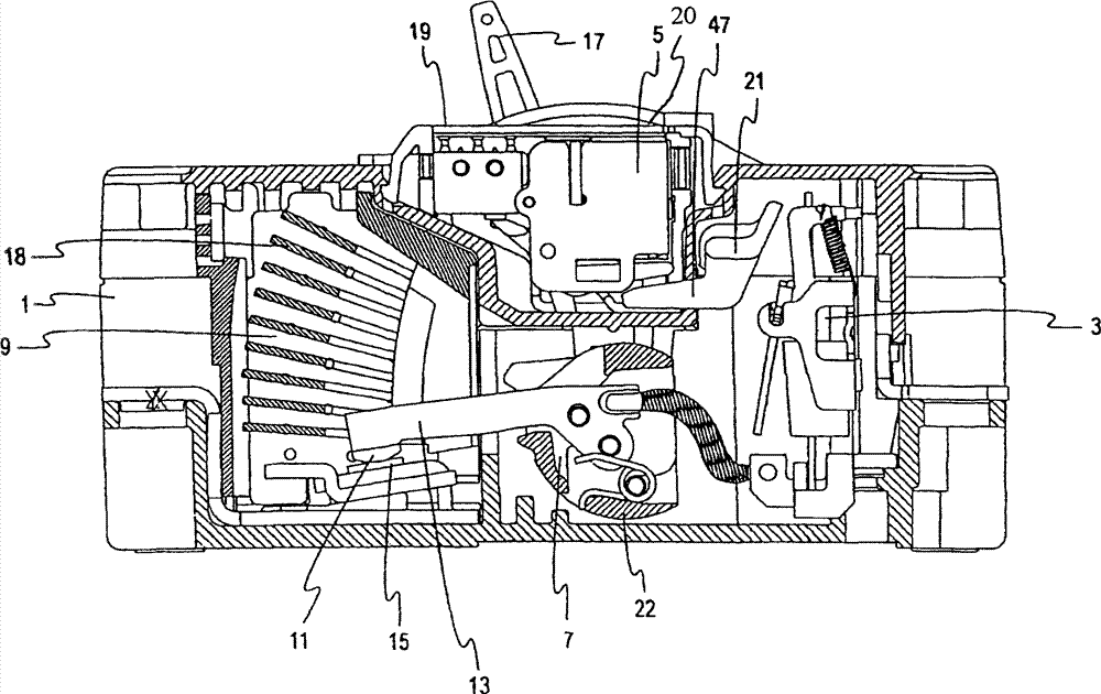
图1为本发明的断路器在关闭位置的截面图;Fig. 1 is a sectional view of a circuit breaker of the present invention in a closed position;
图2为本发明的断路器在打开位置的截面图;Fig. 2 is a cross-sectional view of the circuit breaker of the present invention in an open position;
图3为本发明的断路器在斥开位置的截面图;Fig. 3 is a cross-sectional view of the circuit breaker of the present invention in an open position;
图4为本发明的断路器在断路位置的截面图;Fig. 4 is a cross-sectional view of the circuit breaker of the present invention at the disconnection position;
图5A为本发明的断路器包括电流路径上部分元件的局部组装图;FIG. 5A is a partial assembly diagram of the circuit breaker of the present invention including some components on the current path;
图5B为本发明断路器电流路径上部分元件的分解立体图;Fig. 5B is an exploded perspective view of some components on the current path of the circuit breaker of the present invention;
图6为本发明断路器中PTC材料的进线端子的立体图;Fig. 6 is a perspective view of the incoming terminal of the PTC material in the circuit breaker of the present invention;
图7为本发明断路器中PTC材料的中间端子的立体图;7 is a perspective view of an intermediate terminal of a PTC material in a circuit breaker of the present invention;
图8为本发明断路器中PTC材料的负载端子的立体图;Fig. 8 is a perspective view of the load terminal of the PTC material in the circuit breaker of the present invention;
图9为本发明断路器中非PTC材料的负载端子的立体图;9 is a perspective view of a load terminal of a non-PTC material in a circuit breaker of the present invention;
图10为本发明断路器中非PTC材料的进线端子的立体图;Fig. 10 is a perspective view of an incoming line terminal of a non-PTC material in a circuit breaker of the present invention;
图11为本发明断路器中非PTC材料的中间端子的立体图;Fig. 11 is a perspective view of an intermediate terminal of a non-PTC material in the circuit breaker of the present invention;
图12A为本发明断路器中动触点为独立元件的动触臂的立体图;Fig. 12A is a perspective view of a movable contact arm in which the movable contact is an independent component in the circuit breaker of the present invention;
图12B为本发明断路器中包含动触点构型的动触臂的立体图。Fig. 12B is a perspective view of a moving contact arm including a moving contact configuration in the circuit breaker of the present invention.
具体实施方式Detailed ways
图1、图2、图3和图4显示了关闭、打开、斥开和断路位置的断路器1。断路器1通常包含有进线端子410、静触点15、动触臂13、中间端子406、负载端子400以及跳闸机构3,此外还设有手柄机构5和灭弧机构9等。Figures 1, 2, 3 and 4 show the circuit breaker 1 in the closed, open, opened and tripped positions. The circuit breaker 1 generally includes an
如图1所示,断路器1在关闭位置,动触臂13上的动触点11与静触点15接触。动触点11和静触点15之间相连接,从而导通了断路器1的电流路径,使得断路器1的电气系统正常工作。手柄机构5包括手柄17,手柄17伸出断路器1外壳之外且可在一手柄槽(未显示)内摆动,该手柄17可以操作断路器1,从而使断路器1有一种或多种功能。手柄17可以用于手动重置断路器1,也可以显示断路器1的状态。在“关闭”状态下,如图1所示,手柄17位于手柄槽的关闭缘19。作为跳闸机构3一部分的脱扣杆21处于未断路位置,该脱扣杆21具有位于线路中的长表面指状物47,该长表面指状物47具有水平平面。As shown in FIG. 1 , the circuit breaker 1 is in the closed position, and the
如图2所示,断路器1在“打开”位置,“打开”位置是手动控制位置,手柄17被手动移动到手柄槽的打开缘20(见图4)。在该位置,动触臂13运动到灭弧机构9中的多个弧板18所处的空间中,脱扣杆21在未断路位置保持不动。As shown in Figure 2, the circuit breaker 1 is in the "open" position, which is a manually controlled position, and the
如图3所示,断路器1在“斥开”位置,超过可接受的预设阙值一定百分比的值的电流引起电磁力,其克服了动触臂13上的预加力,这使动触臂13在灭弧机构9中经弧板18所处空间向手柄17一侧旋转。在该位置处,动触臂13具有一壳体22,该壳体22保持与其在“关闭”位置相同的位置,脱扣杆21保持与其在“关闭”和“打开”位置相同的位置。手柄17保持与“关闭”状态中相同的位置。As shown in Figure 3, the circuit breaker 1 is in the "repulsion" position, and the current exceeding the acceptable preset threshold value by a certain percentage causes an electromagnetic force, which overcomes the pre-stress force on the
在给定时间内,如果断路器1中的电流强度增加,会导致“断路”位置。如图4所示,断路器1较长时间暴露于高电流强度会激活跳闸机构3,使得动触臂13和动触臂13的壳体22向手柄17方向旋转,从而断开电流。手柄17保持在“关闭”和“打开”位置之间的位置。脱扣杆21上的断路横梁此时为脱扣状态。为使电路复位,手柄17必须先被移动到“打开”位置,然后再移动到“关闭”位置。If, within a given time, the intensity of the current in circuit breaker 1 increases, it will result in the "open circuit" position. As shown in FIG. 4 , when the circuit breaker 1 is exposed to a high current intensity for a long time, the tripping mechanism 3 will be activated, so that the
如图5A所示,电流从要保护的电路流入,依次经过进线端子410、静触点15、动触臂13(动触臂13端部可以设置有作为独立元件的动触点11)、第二软电缆408、中间端子406、双金属片或三金属片404(其为断路器1的热跳闸元件或组件的一部分)、第一软电缆402以及负载端子400。静触点15安装在进线端子410上。这样,要保护的电路与断路器1中的上述一系列元件形成了串联的电路路径。As shown in Figure 5A, the current flows in from the circuit to be protected, and passes through the
图5B仅显示了电流路径元件,电流依次经过进线端子410、静触点15、动触臂13(动触臂13上可以固定作为独立元件的动触点11)、第二软电缆408、中间端子406、双金属片或三金属片404(包括断路器的热跳闸元件或组件的一部分)、第一软电缆402以及负载端子400,其中动触臂13上不固定作为独立元件的动触点11。Figure 5B only shows the current path components, and the current passes through the
为了利于断路器1的斥开特点,将进线端子410设置为反向弯折构型,以加长进线端子410的长度,且使其中的电流路径增长,具体是,进线端子410的反向弯折构型具有一反向弯折体,以便翻转电流的方向,也翻转静触点15区域中的电磁场方向,以响应电磁力来促进所述静触点15相对于所述动触点11的斥开操作,其中所述电磁力是由响应流经所述断路器1的所述电流路径的预定幅度的浪涌电流产生。图6也显示了进线端子的这一特点。关于进线端子410的反向弯折体的特点及结构内容将在下面详叙。In order to facilitate the repelling characteristics of the circuit breaker 1, the
在本发明中,至少动触臂13是由正温度系数(PTC)材料构成,另外,进线端子410、中间端子406和负载端子400中的一个或多个也可以同时由正温度系数(PTC)材料构成。这样可以保护双金属片断路装置或元件404免受过热影响,而不干扰电流流经断路器。In the present invention, at least the
在小于15安培电流的断路器中,进线端子410、中间端子406、负载端子400和动触臂13同时由正温度系数(PTC)材料构成;在等于15安培电流的断路器1中,中间端子406和动触臂13同时由正温度系数(PTC)材料构成;在大于15安培电流断路器中,仅动触臂13由正温度系数(PTC)材料构成。使用电流路径上的元件由正温度系数(PTC)材料构成时可以显著降低最大允通能量(kA2s),在一个极限短路分断试验中,可以发现,动触臂13和中间端子406同时由正温度系数(PTC)材料构成与仅中间端子406由正温度系数(PTC)材料构成相比,前者的最大允通能量(kA2s)比后者低60%以上,由此可见,断路器1的性能得到了极大的改善。In a circuit breaker with a current of less than 15 amperes, the
图6、图7和图8分别显示了用PTC材料构成的进线端子410、中间端子406和负载端子400。FIG. 6, FIG. 7 and FIG. 8 respectively show the
如图6所示,所述进线端子410构型为向所述动触点11呈现反向电流路径,其中进线端子410主要由弯曲体以及反向弯折体两部分构成,该弯曲体具有上平板即为连接器端部425、下平板426以及位于上平板及下平板426之间且相互连接的U型切口部,通过该U型切口而构成了切除区域420、422和424;该反向弯折体具有第一臂412及相对于该第一臂412反折的第二臂416(结合图5A所示),该第一臂412的一端与下平板426连接,其另一端反向弯折后与第二臂416连接,其连接区域为414,在该第二臂416上设置有一个或多个用于安装静触点15的孔418,该反向电流路径依次为:连接器端部425、切除区域420、422和424、下平板426、第一臂412、翻转到第二臂416(孔418)、静触点15及动触点11等,由此加长了进线端子410的电流路径。进线端子410所使用的PTC材料用量及其截面构型和长度可以确定电阻性质。图6的PTC材料进线端子410构型在许多方面与图8所示的普通端子构型不同(其将后述)。图6所示的进线端子410包括通常为U型或切除区域420、422和424,除了相对较大的连接器端部425外,切除区域420、422和424的横截面积基本恒定。另装配静触点15的第二臂416的横截面积相对较大。As shown in FIG. 6, the
如图7显示了PTC材料的中间端子406的立体图,其为一种现有的PTC材料的中间端子结构示意图,该中间端子406有放大其截面尺寸的连接部分435,或者,其有如附图标记430所示的基本恒定并受控制的截面尺寸。类似地,图8所示,其为现有的PTC材料的负载端子结构示意图,该负载端子400有放大其横截面积尺寸的连接部分445,或者其有如附图标记440所示的恒定截面。在一个具体实施例中,进线端子410、中间端子406和负载端子400的横截面积是2mm×4mm。在这种截面的实施例中,中间端子406长50mm,进线端子410长100mm,负载端子400长40mm。Figure 7 shows a perspective view of an
另外,本发明在所述动触臂13由正温度系数材料构成的情况下,所述进线端子410、所述中间端子406和所述负载端子400也可以采用非PTC材料,这样,所述非PTC材料的进线端子、中间端子和负载端子的结构均与图6-图8所示的PTC材料的进线端子、中间端子和负载端子的结构不同,即为图9-图11所示,其中所述非PTC材料的进线端子、中间端子和负载端子的具体结构为现有技术,在此不再详述。In addition, in the present invention, when the
图12A和图12B分别显示了由PTC材料构成的不同构型的动触臂13。其中,颈部452具有恒定的截面,并且尾部453的截面大于颈部452的截面。在图12A中,头部451的截面与颈部452的截面基本相同,在头部451上可以通过焊接等方式固定作为独立元件的动触点11,其中该动触点11不使用PTC材料。在图12B中,头部451位置的截面面积大于颈部452的截面面积。图12A和图12B所示的动触臂13通过其所使用的PTC材料用量及其截面和长度可以确定电阻性质。在一个具体实施例中,动触臂13颈部452的截面是2mm×4mm,对此再根据PTC材料的电阻率及电流等级(例如电流大于或小于或等于15安培),即可确定出该动触臂13的长度。FIG. 12A and FIG. 12B respectively show different configurations of the
在每种情况下,有效长度指各个端子恒定截面积的部分。In each case, the effective length refers to the portion of the constant cross-sectional area of each terminal.
在本发明的另一个实施例中,当动触臂13、进线端子410、负载端子400和/或中间端子406由PTC材料构成时,其中PTC材料可以使用从例如Carpenter Specialty Alloys公司获得的号合金材料,或者使用从DKAssociates公司获得的Alloy720合金材料。该合金具有优良的电阻性能,包括特殊大电阻和低温度电阻系数。可以通过改变合金成分来以提供不同的电阻率。In another embodiment of the present invention, when the
本发明的优点在于,其断路器采用PTC材料的动触臂,不仅使该断路器性能提高,而且简化了具有PTC材料部件的制作工艺,且大大地降低了断路器的制作成本;此外,本发明还可以将PTC材料的动触臂与进线端子、中间端子和负载端子中至少一个为PTC材料相组合,以满足断路器不同电流量的需求。The advantage of the present invention is that the circuit breaker adopts the movable contact arm of PTC material, which not only improves the performance of the circuit breaker, but also simplifies the manufacturing process of the parts with PTC material, and greatly reduces the production cost of the circuit breaker; in addition, the present invention The invention can also combine the movable contact arm made of PTC material with at least one of the incoming terminal, the intermediate terminal and the load terminal made of PTC material, so as to meet the needs of different current quantities of the circuit breaker.
本领域技术人员应当理解,本发明不限于本文所公开的具体形式和构成,在不脱离本文发明精神的前提下可以对上述描述进行修改、改变和变化。It should be understood by those skilled in the art that the present invention is not limited to the specific forms and configurations disclosed herein, and that modifications, changes and changes can be made to the above description without departing from the spirit of the present invention.
Claims (12)
Priority Applications (1)
| Application Number | Priority Date | Filing Date | Title |
|---|---|---|---|
| CN2010101883899A CN102270552B (en) | 2010-06-01 | 2010-06-01 | Breaker and method for controlling heat energy in breaker |
Applications Claiming Priority (1)
| Application Number | Priority Date | Filing Date | Title |
|---|---|---|---|
| CN2010101883899A CN102270552B (en) | 2010-06-01 | 2010-06-01 | Breaker and method for controlling heat energy in breaker |
Publications (2)
| Publication Number | Publication Date |
|---|---|
| CN102270552A CN102270552A (en) | 2011-12-07 |
| CN102270552B true CN102270552B (en) | 2013-11-20 |
Family
ID=45052800
Family Applications (1)
| Application Number | Title | Priority Date | Filing Date |
|---|---|---|---|
| CN2010101883899A Active CN102270552B (en) | 2010-06-01 | 2010-06-01 | Breaker and method for controlling heat energy in breaker |
Country Status (1)
| Country | Link |
|---|---|
| CN (1) | CN102270552B (en) |
Families Citing this family (2)
| Publication number | Priority date | Publication date | Assignee | Title |
|---|---|---|---|---|
| US9520710B2 (en) * | 2014-06-24 | 2016-12-13 | Eaton Corporation | Thermal trip assembly and circuit interrupter including the same |
| DE102017114227B4 (en) * | 2016-09-30 | 2018-11-29 | Defond Components Limited | Electrical switch unit for an electrical appliance and electrical appliance |
Citations (2)
| Publication number | Priority date | Publication date | Assignee | Title |
|---|---|---|---|---|
| CN1421889A (en) * | 2001-09-14 | 2003-06-04 | 斯夸尔·D公司 | Positive temperature coefficient terminal |
| CN101577197A (en) * | 2008-11-04 | 2009-11-11 | 厦门宏美电子有限公司 | Low-voltage circuit breaker capable of improving breaking capacity |
Family Cites Families (2)
| Publication number | Priority date | Publication date | Assignee | Title |
|---|---|---|---|---|
| JPH01105430A (en) * | 1987-08-13 | 1989-04-21 | Murata Mfg Co Ltd | Self-holding type protective switch |
| JP3588687B2 (en) * | 1997-06-16 | 2004-11-17 | 株式会社ゼクセルヴァレオクライメートコントロール | Air conditioner |
-
2010
- 2010-06-01 CN CN2010101883899A patent/CN102270552B/en active Active
Patent Citations (2)
| Publication number | Priority date | Publication date | Assignee | Title |
|---|---|---|---|---|
| CN1421889A (en) * | 2001-09-14 | 2003-06-04 | 斯夸尔·D公司 | Positive temperature coefficient terminal |
| CN101577197A (en) * | 2008-11-04 | 2009-11-11 | 厦门宏美电子有限公司 | Low-voltage circuit breaker capable of improving breaking capacity |
Also Published As
| Publication number | Publication date |
|---|---|
| CN102270552A (en) | 2011-12-07 |
Similar Documents
| Publication | Publication Date | Title |
|---|---|---|
| CN101211724B (en) | Activation for switching apparatus | |
| JPS6243027A (en) | circuit breaker | |
| CN104813432B (en) | Surge protector with short circuit current protection | |
| CN103620703A (en) | Thermal metal oxide varistor circuit protection device | |
| US20110140827A1 (en) | Circuit protection device | |
| CN101834102B (en) | Overcurrent tripping device of a circuit breaker | |
| CN201601035U (en) | Thermal cutouts and electrical switchgear with thermal cutouts | |
| AU9726201A (en) | Circuit breaker with bypass conductor commutating current out of the bimetal during short circuit interruption and method of commutating current out of bimetal | |
| CN102270552B (en) | Breaker and method for controlling heat energy in breaker | |
| CN112802722A (en) | Static contact structure, contact system and circuit breaker | |
| US6636133B2 (en) | PTC terminals | |
| CN101004987A (en) | circuit breaker trip release | |
| US5268661A (en) | Current throttle technique | |
| US7362207B2 (en) | Electrical switching apparatus and limiter including trip indicator member | |
| CN102810434B (en) | Circuit breaker and thermal trip device thereof | |
| CN101359561B (en) | Release with step type yoke structure and circuit breaker with the release | |
| CN101777462B (en) | Circuit breaker with mechanical overheating protection function | |
| US7397333B2 (en) | Trip unit having bimetal element located outside the yoke | |
| CN213905273U (en) | Static contact structure, contact system and circuit breaker | |
| CN112768288B (en) | A vacuum circuit breaker repelling device and vacuum circuit breaker | |
| CN104517786B (en) | Miniaturized circuit breaker | |
| CN201226330Y (en) | Overload protection unit for pyromagnetic circuit breaker with lower rating current | |
| CN209843646U (en) | Circuit breakers with overvoltage and undervoltage protection components | |
| US5373272A (en) | High current capacity blade for a circuit breaker | |
| ITMI20100257U1 (en) | CURRENT LIMITATION SYSTEM |
Legal Events
| Date | Code | Title | Description |
|---|---|---|---|
| C06 | Publication | ||
| PB01 | Publication | ||
| C10 | Entry into substantive examination | ||
| SE01 | Entry into force of request for substantive examination | ||
| C14 | Grant of patent or utility model | ||
| GR01 | Patent grant |