CN102267174B - Automatic honeycomb ceramic wet blank cutting and forming device - Google Patents
Automatic honeycomb ceramic wet blank cutting and forming device Download PDFInfo
- Publication number
- CN102267174B CN102267174B CN 201110234601 CN201110234601A CN102267174B CN 102267174 B CN102267174 B CN 102267174B CN 201110234601 CN201110234601 CN 201110234601 CN 201110234601 A CN201110234601 A CN 201110234601A CN 102267174 B CN102267174 B CN 102267174B
- Authority
- CN
- China
- Prior art keywords
- installing
- conveyer belt
- saddle
- knife bar
- slideway
- Prior art date
- Legal status (The legal status is an assumption and is not a legal conclusion. Google has not performed a legal analysis and makes no representation as to the accuracy of the status listed.)
- Expired - Fee Related
Links
Images


Abstract
An automatic honeycomb ceramic wet blank cutting and forming device is characterized in that a plurality of gantries (10) are arranged on a delivery working platform, a support (2) is arranged beside the delivery working platform, tool rests (7) are sheathed on a tool bar (5), two ends of the tool bar (5) are arranged in a slideway (H) of the support (2) at two ends, and a transmission rack (3) is arranged at the front end. A bearing (C) is sheathed at two ends of a drive rotation axle (6) and erected in shaft holes of the support (2) at two ends, a transmission gear (4) is sheathed at the front end and meshed with the transmission rack (3). A cutting motor (29) is started, the transmission gear (4) is driven by the drive rotation axle (6) to be meshed with the transmission rack (3), the tool bar (5) drives n tool rests (7) to slide down along the slideway (H), a metal wire blade (21) is embedded in gaps of the gantries (10), a cylindrical wet blank (11) is cut into n+1 sections, and the tool rests (7) return. A transmission motor (24) is started, and the gantries (10) are delivered to a fast conveyor belt (12) from a slow conveyor belt (19) and can be automatically separated off to take away the formed wet blank (11), thus being capable of cutting a plurality of wet blanks (11) at a time.
Description
Technical field
The present invention relates to the honeycomb ceramic carrier of vehicle exhaust three unique catalytic converter, relate in particular to honeycomb ceramic base cutting equipment.
Background technology
In the vehicle exhaust three unique catalytic converter, the carrier of installing, made by the cylinder-shaped honeycomb pottery.Preparation method is the base compacting growth tubular that first will wet, excision forming then, then advance stove and fire typing.Wet base is made with two kinds of extruders usually, and a kind of is horizontal extruder, and a kind of is vertical extruder.The horizontal extruder investment is large, and auxiliary facility requires high, generally is of little use.Vertical extruder is suitable for the making of small lot special-shaped product.When producing the wet base of honeycomb ceramic carrier with vertical extruder, need to make moulding with manually cutting one by one.Not only efficient is low, output is few for this single-piece hand cut mode, and difficult quality guarantee, easily makes wet base distortion, affects the outward appearance of product, and mortality is high, causes the production efficiency of manufactured goods too low.
Summary of the invention
Purpose of the present invention, just be to provide a kind of isolated plant that cuts the honeycomb ceramic base, realize once cutting a plurality of wet bases, enhance productivity, guarantee Forming Quality, save artificial and raw material, increase the output of manufactured goods, improve the equipped performance of the honeycomb ceramic carrier of vehicle exhaust three unique catalytic converter.
task of the present invention is completed like this: design a kind of honeycomb ceramic base surface trimming moulding device, be used for making the wet base of vehicle exhaust three unique catalytic converter honeycomb ceramic carrier, by holder base frame, the driven type workbench, support, cutter, transmission system, electrical system constitutes, holder base frame is connected and composed by several saddles, be placed on the driven type workbench, the driven type workbench is installed in respectively on separately Working gantry by conveyer belt at a slow speed and conveyer belt fast, successive formation, support is arranged at a slow speed by conveyor belt side, fix in two end supports, several knife rests of cutter are installed on same knife bar, the knife bar two ends are erected on support, each knife rest and the corresponding setting of each saddle of holding in the palm the base frame, transmission system is by main rotary shaft, travelling gear, driving rack, reductor, drive, driving belt constitutes, electrical system is by driving motor, cutting motor, gauge tap forms, gauge tap is installed in the Working gantry side.Saddle is the cuboid that end face is opened the axial bracket of indent semi arch, be respectively equipped with alignment pin and pin-and-hole on the end face of bracket below, saddle two ends, the alignment pin of front saddle coordinates plug-in mounting with the pin-and-hole of back saddle, several saddles connect and compose holder base frame, the end face bracket of each saddle connects and is connected, and is separated by between each saddle end face and leaves the gap.The driven type workbench is by conveyer belt at a slow speed and transmits fast band and be connected before and after being installed in respectively on separately Working gantry and form, and is provided with the rectangle positioning baffle in the end of conveyer belt at a slow speed, is vertically fixed on the Working gantry of conveyer belt at a slow speed.Working gantry is rectangle desktop workbench, vertically have row's axis hole on the panel of both sides, in establish bearing, installing transmission roll shaft, Working gantry below installing driving motor, the large drive wheel that connects reductor by driving belt connects the driving shaft at a slow speed of conveyer belt at a slow speed, the axle quickly that little drive connects quick conveyer belt more again, and driving motor is by the transmission switch of wire connecting working table frame side.Cutter is made of installing wire blade on knife rest, and knife rest is U-shaped three frame structures, and bottom opening place's installing wire is as blade.Top one end thickening has the knife bar hole, and the centre installs knife bar, and knife rest is spaced on knife bar, and corresponding with the saddle of holder base frame, the two ends of knife bar are erected at respectively in the slideway of two end supports.Support is two vertical board-like stands, be erected at respectively the other two ends of Working gantry side of conveyer belt at a slow speed, between the end face of two seat supports by the top board reinforcement by connection, have the slotted hole slot slideway by the below inclination to the inside of top, the outside on the plate face on support top, have axis hole on the plate face below the slideway upper end, bearing set installing main rotary shaft, the end of installing knife bar in slideway, installing optoelectronic switch transmitting terminal on the plate face above the slideway lower end, on the plate face of below, slideway lower end, installing optoelectronic switch receiving terminal, be communicated with cutting motor by wire.The main rotary shaft two ends are sleeved in the bearing of two end supports, with conveyer belt is parallel at a slow speed, the middle part arbor wheel of main rotary shaft connects the cutting motor of below by driving belt, one end frame of main rotary shaft is contained on front-end bracket, inboard fixing installing travelling gear is meshed with the driving rack of knife bar front end installing, and the other end is erected on rear end support, inner fixing installing skid wheel contacts cooperation with the slide plate of knife bar rear end installing.The two ends axle journal of knife bar is set with in the slideway that bearing roller is installed in two end supports, the inboard installing driving rack of front end-journal, be meshed with the travelling gear of main rotary shaft front end installing, the fixing installing in the inboard of rear end-journal slide plate is taken turns rolling with the skid on main rotary shaft and is coordinated.Intercept the wet base of one section continuous oval column from vertical extruder during use, be seated in the semicircle arcuation groove of the holder base top of support that saddle is linked to be, to ask the base frame entirely to be placed at a slow speed on conveyer belt, align with positioning baffle and just get in the rear end, the gap between each saddle is just in time corresponding with the wire blade of each cutter of cutter.The cutting button is pressed to after good in the mutual alignment of confirming each device, the holder base frame operation of cutter along slideway to oblique below, and the base segmentation of wetting from the vertical plane of wire blade is cut off, and continuous wet base elongated cylinder is become the n+1 section by n wire blade cuts.Press the return push-button of cutting in button, cutter returns to the oblique upper original position along slideway again, and it is moving that wet base still is placed on holder base frame the original place.At this moment, press the transmission button, at a slow speed conveyer belt and fast conveyer belt rotate simultaneously, the conveyer belt holder saddle of holder base frame transmits to quick conveyer belt direction at a slow speed, delivers to the joining place with quick conveyer belt, the front end saddle is sent to quick conveyer belt one by one.Because quick conveyer belt is faster than the speed of service of conveyer belt at a slow speed, when the front end saddle runs on quick conveyer belt with the wet base of well cutting, the speed of service is accelerated suddenly, fast conveyer belt with front end saddle band to far-end, the alignment pin that adjacent two saddles connect is extracted from pin-and-hole, saddle in front is moving on conveyer belt fast with one section wet base finished product of well cutting, with saddle automatic trip on the conveyer belt at a slow speed of back from.Each saddle of back reaches quick conveyer belt by conveyer belt at a slow speed successively, mutually automatic trip from, the wet base finished product with well cutting moves to far-end separately, rolls off the production line to conveyer belt far-end fast.
Implement according to technique scheme, can realize surface trimming, the separation of honeycomb ceramic base, realize the disposable excision forming polylith base that wets, enhance productivity, save manpower, material, reduce cost of manufacture, guarantee product quality, increase qualified production, improving honeycomb ceramic carrier is that vehicle exhaust three is without the equipped performance of catalytic cleaner, increase economic efficiency, reached preferably predetermined purpose.
Description of drawings
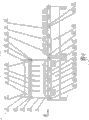
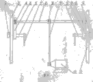
Fig. 1 is whole installing structural representation of the present invention;
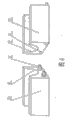
Fig. 2 is that the A of Fig. 1 is to view;
Fig. 3 is the structural representation that the knife rest (7) in Fig. 2 is positioned at lower end position;
Fig. 4 is the structural representation of saddle of the present invention (10);
Fig. 5 is optoelectronic switch schematic diagram of the present invention;
Fig. 6 is driving motor of the present invention (24) transmission schematic diagram;
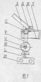
Fig. 7 is cutting motor of the present invention (29) transmission schematic diagram;
Fig. 8 is cutting motor of the present invention (29) and the equipped structural representation of main rotary shaft (6).
in figure, 1-positioning baffle, 2-support, 3-driving rack, 4-travelling gear, 5-knife bar, 6-main rotary shaft, 7-knife rest, 8-skid wheel, 9-slide plate, 10-saddle, 11-wet base, 12-fast conveyer belts, 13-live-roller, 14-transmission roll shaft, 15-Working gantry, 16-quickly axles, 17-at a slow speed driving shafts, 18-transmission switch, 19-at a slow speed conveyer belts, 20-cutting switch, 21-wire blade, 22-optoelectronic switch transmitting terminal, 23-optoelectronic switch receiving terminal, 24-driving motor, 25-reductor, 26-belt pulley, 27-little drive, 28-large drive wheel, 29-cutting motor, A-line of vision symbol, C-bearing, G-bearing roller, T-top board, H-slideway, R-bracket, X-alignment pin, K-pin-and-hole, L-wire, S-ray, P-driving belt, N-output wheel, Z-arbor wheel.
The specific embodiment
Below in conjunction with accompanying drawing, embodiments of the present invention are described.
Consult Fig. 1, holder base frame, driven type workbench, cutter, support 2 constitute overall structure of the present invention with transmission system, electrical system.Cover belt at a slow speed conveyer belt 19 and fast conveyer belt 12 be set with transmission roll shaft 14 and be installed on separately Working gantry 15, respectively by driving shaft 17 at a slow speed and quickly axle 16 drive and rotate, successive, formation driven type workbench.Cutting switch 20 and transmission switch 18 are installed respectively in the side of Working gantry 15.Support 2 is two vertical plate type structures, is fixed on by Working gantry 15 sides of conveyer belt 19 at a slow speed, and parallel the setting, the end face of rear and front end support 2 is by top board T reinforcement by connection.Working gantry 15 ends of conveyer belt 19 are provided with positioning baffle 1 at a slow speed.Several knife rests 7 are sleeved on knife bar 5, consist of cutter, and knife bar 5 two ends are erected in slideway H on two end supports 2, the inboard suit of end axle head driving rack 3, the inboard installing of other end axle head slide plate 9.Offer driving rack 3 engagements on axis hole installing main rotary shaft 6, one ends installing travelling gears 4 and knife bar 5 on the lower plate face of slideway H, other end installing skid wheel 8 coordinates with slide plate 9 on knife bar 5.Holder base frame is connected and composed by several saddles 10, is placed at a slow speed on conveyer belt 19, and the wet base 11 of elongated cylinder to be processed is placed on a plurality of saddles 10.Cutter moves to oblique below, and the wet base 11 of elongated cylinder is cut into a plurality of formation wet blanks 11.Wet base 11 finished products of completing cutting are shelved on respectively on each self-corresponding saddle 10, are sent on quick conveyer belt 12 by conveyer belt 19 at a slow speed.Because the saddle 10 on quick conveyer belt 12 is faster than saddle 10 transfer rates on conveyer belt 19 at a slow speed, front end saddle 10 automatic trips are from rear end saddle 10, move forward with the wet base 11 of well cutting, transfer out to quick conveyer belt 12 front ends one by one.The irregular wet base 11 in two ends can remove, the wet base 11 standard moulding of middle five wet bases.
Consult Fig. 2, Fig. 3, rear end forward end direction by support 2 is seen, support 2 is arranged side by side with cutter and transmission workbench, slideway H support 2 tops by on the transmission workbench direction of direction side-lower tilt, the end bearing set roller G of knife bar 5 is inlaid in slideway H groove, knife bar 5 the inners are sleeved in the axis hole of driving rack 3 lower ends, and the body of rod of knife bar 5 is fixedly set in the connecting hole of knife rest 7 end faces.Have axis hole on the support 2 plate faces below slideway H upper end, main rotary shaft 6 outside axle head bearing set C are installed in axis hole, inboard axle head suit travelling gear 4, be meshed with driving rack 3, the knife bar 5 that makes driving rack 3 drive cutter moves up and down along slideway H.The transmission workbench cover belt at a slow speed conveyer belt 19 be erected on Working gantry 15, driven by driving shaft at a slow speed 17, the saddle 10 of holder base frame is placed at a slow speed above conveyer belt 19, honeycomb ceramic base 11 is placed in semi arch bracket R on saddle 10.In the end of Working gantry 15, positioning baffle 1 is set, the saddle 10 of outermost end is close to positioning baffle 1, determines the position.When cutter is cut down to wet base 11 by oblique upper, the wire blade 21 of knife rest 7 just in time embeds in the space that is separated by between each saddle 10, and when cutter moved to slideway H lower end downwards, wire blade 21 base 11 that will wet cut off fully.Driving rack 3 is along in the downward running of slideway H, and the driving rack 3 of knife bar 5 suits remains engagement with travelling gear 4.
Consult Fig. 4, the saddle 10 of holder base frame is rectangular structure, end face has the axial bracket R of indent semicircle arcuation, saddle 10 end faces of bracket R below, one end is with two alignment pin X arranged side by side, the other end has corresponding two pin-and-hole K, and the alignment pin X of back saddle 10 front ends can coordinate with the pin-and-hole K plug-in mounting of front saddle 10 rear ends, is separated with mutually the gap of 10mm left and right between adjacent two saddle 10 end faces after connection.
Consult Fig. 5, installing optoelectronic switch transmitting terminal 22 above the slideway H bottom of support 2 connects power supply by wire L, and below installing optoelectronic switch receiving terminal 23 connects cutting motor 29 by wire L.When knife bar 5 moves to slideway H bottom by driving rack 3 drives along slideway H, the ray S that optoelectronic switch transmitting terminal 22 is sent interdicts, optoelectronic switch receiving terminal 23 can not receive photosignal, automatically cut off the signal that is connected with cutting motor 29, cutting motor 29 stops operating, knife bar 5 stops downward operation automatically, and this moment, cutter was fully with wet base 11 excision formings on saddle 10.
Consult Fig. 6, driving motor 24 is connected with reductor 25 by driving belt P, be installed in below transmission Working gantry 15, the large drive wheel 28 of reductor 25 connects the driving shaft at a slow speed 17 of conveyer belt 18 at a slow speed by driving belt P, brief biography driving wheel 27 connects the axle quickly 16 of quick driving-belt 12 by driving belt P, drive respectively to cover the tape conveyor belt operation.
Consult Fig. 7, Fig. 8, cutting motor 29 coordinates with the main rotary shaft 6 that is erected between two end supports 2 by the arbor wheel Z at driving belt P connection main rotary shaft 6 middle parts.The inboard axle head suit of main rotary shaft 6 one ends travelling gear 4, the inboard axle head suit of other end skid wheel 8.Travelling gear 4 is meshed with the driving rack 3 of knife bar 5 inboard axle heads.The some knife rests 7 of knife bar 5 suit, two ends are erected in slideway H on support 2, the inner installing driving rack 3 of an end knife bar 5, and with travelling gear 4 engagements, the inner installing slide plate 9 of other end knife bar 5 coordinates with the skid wheel 8 of main rotary shaft 6 homonymy the inners.Cutting motor 29 connects arbor wheel Z by driving belt P and drives main rotary shaft 6 rotations, by driving rack 3 engagements of travelling gear 4 with knife bar 5, driving knife bar 5 moves along the slideway H on support 2, thereby make cutter realize cutting downwards, the action of upwards returning, complete the course of work of honeycomb ceramic base 11 excision formings that will place on the saddle 10 on conveyer belt 19 at a slow speed.
Adopt the present invention to be used for cutting processing honeycomb ceramic base 11, convenient, fast, automaticity is high, can a plurality of qualified wet bases 11 of one-shot forming, quality is good, efficient is high, has reduced waster, saved raw material and artificial, improve operating mode, overcome manually-operated error and loss, realized the mechanization production of honeycomb ceramic base 11, guaranteed the quality of vehicle exhaust three unique catalytic converter finished product, matching performance is good, and economic benefit is high, and future develop is good.
Claims (4)
1. honeycomb ceramic base surface trimming moulding device, be used for making the wet base of vehicle exhaust three unique catalytic converter honeycomb ceramic carrier, it is characterized in that by holder base frame, the driven type workbench, support (2), cutter, transmission system, electrical system constitutes, holder base frame is connected and composed by several saddles (10), be placed on the driven type workbench, saddle (10) is opened the cuboid of the axial bracket of indent semi arch (R) for end face, be respectively equipped with alignment pin (X) and pin-and-hole (K) on the end face of saddle (10) two ends brackets (R) below, the alignment pin (X) of front saddle (10) coordinates plug-in mounting with the pin-and-hole (K) of back saddle (10), several saddles (10) connect and compose holder base frame, the end face bracket (R) of each saddle (10) connects and is connected, be separated by between each saddle (10) end face and leave the gap, the driven type workbench is installed in respectively on separately Working gantry (15) by conveyer belt (19) at a slow speed and conveyer belt (12) fast, successive formation, be provided with rectangle positioning baffle (1) in the end of conveyer belt (19) at a slow speed, be vertically fixed on the Working gantry (15) of conveyer belt (19) at a slow speed, Working gantry (15) is rectangle desktop workbench, vertically have row's axis hole on the panel of both sides, in establish bearing, installing transmission roll shaft (14), support (2) is arranged at a slow speed by conveyer belt (19) side, fix in two end supports, several knife rests (7) of cutter are installed on same knife bar (5), knife bar (5) two ends are erected on support (2), each knife rest (7) and the corresponding setting of each saddle (10) of holding in the palm the base frame, transmission system is by main rotary shaft (6), travelling gear (4), driving rack (3), reductor (25), drive, driving belt (P) constitutes, electrical system is by driving motor (24), cutting motor (29), gauge tap forms, gauge tap is installed in Working gantry (15) side, Working gantry (15) below installing driving motor (24), the large drive wheel (28) that connects reductor (25) by driving belt (P) connects the driving shaft at a slow speed (17) of conveyer belt (19) at a slow speed again, little drive (27) connects the axle quickly (16) of quick conveyer belt (12) again, driving motor (24) is by the transmission switch (18) of wire (L) connecting working table frame (15) side.
2. according to honeycomb ceramic base surface trimming moulding device claimed in claim 1, it is characterized in that described cutter is made of knife rest (7) upper installing wire blade (21), knife rest (7) is U-shaped three frame structures, bottom opening place installing wire is as blade, top one end thickening, have the knife bar hole, the centre installs knife bar (5), knife rest (7) is spaced on knife bar (5), corresponding with the saddle (10) of holder base frame, the two ends of knife bar (5) are erected at respectively in the slideway (H) of two end supports (2), support (2) is two vertical board-like stands, be erected at respectively the other two ends of Working gantry (15) side of conveyer belt (19) at a slow speed, between the end face of two seat supports (2) by top board (T) reinforcement by connection, have the slotted hole slot slideway (H) by the below inclination to the inside of top, the outside on the plate face on support (2) top, have axis hole on the plate face of below, slideway (H) upper end, bearing set (C) installing main rotary shaft (6), the end of installing knife bar (5) in slideway (H), installing optoelectronic switch transmitting terminal (22) on the plate face of top, slideway (H) lower end, installing optoelectronic switch receiving terminal (23) on the plate face of below, slideway (H) lower end, be communicated with cutting motor (29) by wire (L).
3. according to honeycomb ceramic base surface trimming moulding device claimed in claim 1, main rotary shaft (6) two ends that it is characterized in that described transmission system are sleeved in the bearing (C) of two end supports (2), with conveyer belt (19) is parallel at a slow speed, the middle part arbor wheel (Z) of main rotary shaft (6) connects the cutting motor (29) of below by driving belt (P), one end frame of main rotary shaft (6) is contained on front-end bracket (2), inboard fixing installing travelling gear (4), be meshed with the driving rack (3) of knife bar (5) front end installing, the other end is erected on rear end support (2), inner fixing installing skid wheel (8), contact cooperation with the slide plate (9) of knife bar (5) rear end installing.
4. according to honeycomb ceramic base surface trimming moulding device claimed in claim 1, the two ends axle journal that it is characterized in that described knife bar (5) is set with in the slideway (H) that bearing roller (G) is installed in two end supports (2), the inboard installing driving rack (3) of front end-journal, be meshed with the travelling gear (4) of main rotary shaft (6) front end installing, the fixing installing in the inboard of rear end-journal slide plate (9) is taken turns (8) rolling with the skid on main rotary shaft (6) and is coordinated.
Priority Applications (1)
| Application Number | Priority Date | Filing Date | Title |
|---|---|---|---|
| CN 201110234601 CN102267174B (en) | 2011-08-16 | 2011-08-16 | Automatic honeycomb ceramic wet blank cutting and forming device |
Applications Claiming Priority (1)
| Application Number | Priority Date | Filing Date | Title |
|---|---|---|---|
| CN 201110234601 CN102267174B (en) | 2011-08-16 | 2011-08-16 | Automatic honeycomb ceramic wet blank cutting and forming device |
Publications (2)
| Publication Number | Publication Date |
|---|---|
| CN102267174A CN102267174A (en) | 2011-12-07 |
| CN102267174B true CN102267174B (en) | 2013-05-22 |
Family
ID=45049731
Family Applications (1)
| Application Number | Title | Priority Date | Filing Date |
|---|---|---|---|
| CN 201110234601 Expired - Fee Related CN102267174B (en) | 2011-08-16 | 2011-08-16 | Automatic honeycomb ceramic wet blank cutting and forming device |
Country Status (1)
| Country | Link |
|---|---|
| CN (1) | CN102267174B (en) |
Cited By (1)
| Publication number | Priority date | Publication date | Assignee | Title |
|---|---|---|---|---|
| JP2013147012A (en) * | 2011-12-20 | 2013-08-01 | Sumitomo Chemical Co Ltd | Method and device for cutting honeycomb molded body, and method for manufacturing honeycomb structure |
Families Citing this family (8)
| Publication number | Priority date | Publication date | Assignee | Title |
|---|---|---|---|---|
| CN102581942B (en) * | 2012-03-07 | 2015-05-20 | 深圳顺络电子股份有限公司 | Trimming method for ceramic slab of surface mount device and apparatus thereof |
| CN104191031A (en) * | 2014-08-27 | 2014-12-10 | 长兴县华达耐火有限公司 | Cutting device capable of cutting regenerators conveniently |
| CN104708706B (en) * | 2015-03-31 | 2017-09-22 | 淄博钰润建筑材料有限公司 | Composite insulation boards automatic cutting equipment |
| CN105252635B (en) * | 2015-10-08 | 2017-11-03 | 湖州师范学院 | It is adapted to the surface trimming transmitting device of different tube diameters earthen-ware pipe moulded pottery not yet put in a kiln to bake |
| CN105252636A (en) * | 2015-10-08 | 2016-01-20 | 魏玉兰 | Automatic cutting and conveying device for semi-finished ceramic tube |
| CN105501623B (en) * | 2016-02-03 | 2018-04-17 | 洛阳中冶重工集团有限公司 | A kind of aerated concrete products transferring pallet |
| CN105643780B (en) * | 2016-03-29 | 2018-07-10 | 谢光海 | Ceramic honeycomb catalyst cutting machine |
| CN114888946B (en) * | 2022-06-06 | 2023-06-23 | 常州市赫铭自动化科技有限公司 | Turnover separator for honeycomb ceramic wet blank and foam tool |
Citations (5)
| Publication number | Priority date | Publication date | Assignee | Title |
|---|---|---|---|---|
| JP2948251B2 (en) * | 1990-01-29 | 1999-09-13 | 株式会社下村製作所 | Cutting method for brittle materials |
| CN201279832Y (en) * | 2008-09-17 | 2009-07-29 | 丁建盛 | Multi-cutter assembly and ceramic cutting machine having the same |
| CN101574830A (en) * | 2008-08-15 | 2009-11-11 | 山东矿机迈科建材机械有限公司 | Clay bar vertical splitter |
| CN101817201A (en) * | 2010-03-23 | 2010-09-01 | 李社清 | Full automatic blanking machine |
| CN201645634U (en) * | 2009-11-26 | 2010-11-24 | 贵州建新南海科技股份有限公司 | Full-automatic hydraulic blank cutter |
-
2011
- 2011-08-16 CN CN 201110234601 patent/CN102267174B/en not_active Expired - Fee Related
Patent Citations (5)
| Publication number | Priority date | Publication date | Assignee | Title |
|---|---|---|---|---|
| JP2948251B2 (en) * | 1990-01-29 | 1999-09-13 | 株式会社下村製作所 | Cutting method for brittle materials |
| CN101574830A (en) * | 2008-08-15 | 2009-11-11 | 山东矿机迈科建材机械有限公司 | Clay bar vertical splitter |
| CN201279832Y (en) * | 2008-09-17 | 2009-07-29 | 丁建盛 | Multi-cutter assembly and ceramic cutting machine having the same |
| CN201645634U (en) * | 2009-11-26 | 2010-11-24 | 贵州建新南海科技股份有限公司 | Full-automatic hydraulic blank cutter |
| CN101817201A (en) * | 2010-03-23 | 2010-09-01 | 李社清 | Full automatic blanking machine |
Cited By (1)
| Publication number | Priority date | Publication date | Assignee | Title |
|---|---|---|---|---|
| JP2013147012A (en) * | 2011-12-20 | 2013-08-01 | Sumitomo Chemical Co Ltd | Method and device for cutting honeycomb molded body, and method for manufacturing honeycomb structure |
Also Published As
| Publication number | Publication date |
|---|---|
| CN102267174A (en) | 2011-12-07 |
Similar Documents
| Publication | Publication Date | Title |
|---|---|---|
| CN102267174B (en) | Automatic honeycomb ceramic wet blank cutting and forming device | |
| CN201456115U (en) | Device for copper foil strip-shaped hobbing | |
| CN116001012B (en) | Cutting machine for crawling pad processing and cutting method thereof | |
| CN201735656U (en) | Metal net double wave forming machine | |
| CN218425130U (en) | Copper tab punching lithium metal pole piece forming machine | |
| CN214882508U (en) | Automatic slitting mechanism | |
| CN115649919A (en) | Hot-melting cutting machine and cutting method thereof | |
| CN212761519U (en) | Carriage plate forming and cutting device | |
| CN210795205U (en) | Base station antenna insulation piece production line | |
| CN209140991U (en) | One kind, which is ridden, orders knife cutting apparatus in imperial line | |
| CN211702560U (en) | High-efficient multilayer printed wiring board V cuts device | |
| CN111842557A (en) | Automatic system for metal plate bending | |
| CN110802871A (en) | Slitting indenting machine for cutting | |
| CN101856686B (en) | Double wave metal net shaping machine | |
| CN212286092U (en) | Bilateral device is cut to panel of composite sheet production line | |
| CN211164209U (en) | Clamping mechanism for carton die cutting machine | |
| CN217573128U (en) | Automatic silica gel feeding device | |
| CN216400694U (en) | Full-automatic edge-covering splitting machine | |
| CN220796383U (en) | A roll over strip device for chip resistor production | |
| CN213290876U (en) | Vertical cutting special device for ultralong U-shaped glass | |
| CN111497320B (en) | Multidirectional positioning mechanism of carton production | |
| CN216031004U (en) | Foam board cutting tool | |
| CN220465950U (en) | Film glove bagging machine convenient for waste collection | |
| CN220129640U (en) | Quick side cut device | |
| CN212370882U (en) | Automatic system for metal plate bending |
Legal Events
| Date | Code | Title | Description |
|---|---|---|---|
| C06 | Publication | ||
| PB01 | Publication | ||
| C10 | Entry into substantive examination | ||
| SE01 | Entry into force of request for substantive examination | ||
| C14 | Grant of patent or utility model | ||
| GR01 | Patent grant | ||
| C17 | Cessation of patent right | ||
| CF01 | Termination of patent right due to non-payment of annual fee |
Granted publication date: 20130522 Termination date: 20130816 |