CN102261513A - Inlet/exhaust valve for sewage containing lots of impurities and gases - Google Patents
Inlet/exhaust valve for sewage containing lots of impurities and gases Download PDFInfo
- Publication number
- CN102261513A CN102261513A CN201110191891XA CN201110191891A CN102261513A CN 102261513 A CN102261513 A CN 102261513A CN 201110191891X A CN201110191891X A CN 201110191891XA CN 201110191891 A CN201110191891 A CN 201110191891A CN 102261513 A CN102261513 A CN 102261513A
- Authority
- CN
- China
- Prior art keywords
- air outlet
- valve
- valve body
- sewage
- exhaust valve
- Prior art date
- Legal status (The legal status is an assumption and is not a legal conclusion. Google has not performed a legal analysis and makes no representation as to the accuracy of the status listed.)
- Granted
Links
Images


Abstract
The invention relates to a sewage inlet/exhaust valve, specifically to an inlet/exhaust valve for sewage containing lots of impurities and gases. The exhaust valve is provided with a gas vent having an enlarged size, which is advantageous for the exhausting of a large quantity of gases in the sewage, and simultaneously capable of preventing blockage; the gas vent is under the protection of a guide rod on a floating ball without contacting with bubbles easily incrusted in the sewage gases, thereby reducing blockage and ensuring long-term operation; besides, the position of the floating ball is in the middle position, so that the diameter of the whole valve body is reduced; and a circular floating ball is employed so that the contact area thereof with the liquid level can be widened and the length of the valve body can be also reduced. The exhaust valve overcomes the defects of impurity blockage and low gas output caused by a small gas outlet of the existing sewage inlet/exhaust valve.
Description
Technical field
The present invention relates to a kind of sewage air inlet and exhaust valve, specifically a kind ofly be used for that impurity is many, the air inlet and exhaust valve of large-minded sewage.
Background technique
Outlet valve is of a great variety at present, but the sewage outlet valve is less relatively.What adopt usually in existing is the sewage composite exhaust valve, as shown in Figure 1 sewage outlet valve commonly for example, valve body includes parts such as lever and ball float, and wherein oval ball float is near a side of valve body, lever is positioned at the corresponding side of ball float, and bonnet is positioned at a side of valve gap.When the valve body water filling, ball float drops to the bottom of valve body under action of gravity, and a large amount of pressed gas are discharged rapidly from exhaust port.After air is discharged, the water in the pipe in valve body lower portion enters valve, the ball float come-up in the valve body, up to movable masthead to the valve port place, and air inlet and exhaust valve is closed automatically and is stopped exhaust and do not sluice.The air that dissolves in the water in the pipe enters in the valve, and the water surface descends gradually in the valve, and motion bar is held and can not be descended automatically by gas.Reduce to ball float when following when the water surface in the valve body, ball float is relied on power for support, and valve port is opened and given vent to anger in a large number.The existing shortcoming of this class valve is a complex structure at present, and stressed member is more, and is bulky, and the air outlet is too small, causes impurity to stop up the air outlet easily.
Summary of the invention
The present invention is directed to the existing complex structure of existing sewage air inlet and exhaust valve, stressed member is more, bulky, the air outlet is too small, cause impurity to stop up deficiencys such as air outlet easily, provide a kind of and can be used for that impurity is many, the air inlet and exhaust valve of large-minded sewage, stop up and because the little defective of the too small gas output that causes in air outlet thereby overcome the existing impurity of existing sewage air inlet and exhaust valve.
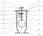
The technical solution adopted for the present invention to solve the technical problems is: a kind of sewage air inlet and exhaust valve comprises valve body, valve gap, ball float, hydrodynamic reciprocating sealing bar, air outlet, air outlet hole and hanger.Described valve gap is fixedly mounted on described valve body upper end, and described valve gap is provided with described air outlet; Be installed with bonnet on the described air outlet, described bonnet is provided with air outlet hole, lower end, described air outlet is equipped with Gask-O-Seal, and place, described air outlet is equipped with hydrodynamic reciprocating sealing bar moving up and down, described seal bar middle part is installed with, be disposed with vent from top to bottom below the above is taken over a business at described hydrodynamic reciprocating sealing bar, gas can be discharged by described air outlet hole by described vent in the valve; Described valve gap lower end and describedly take over a business the lower end Gask-O-Seal all is installed; Described hydrodynamic reciprocating sealing bar is a hollow tubular, and middle lower end is arranged in the described guide rod, and can be up and down in described guide rod; The other end of described guide rod is installed with circular stainless steel floating ball, and described valve gap is provided with hanger, when described guide rod moves up and down because of described ball float, described guide rod can be hung on the described hanger.
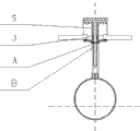
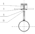
The working principle of valve involved in the present invention is: when valve body injects sewage, the hydrodynamic reciprocating sealing bar hangs on the hanger under action of gravity with the guide rod that is connected with ball float, gas is discharged rapidly through the air outlet, after sewage enters valve body from water intake, the valve body inner float ball promotes guide rod and moves upward at the buoyancy function float downward, and then promotion hydrodynamic reciprocating sealing bar moves upward, until taking over a business to block the air outlet, the bring into operation exhaust in stage of system so far finishes; In system's running, can produce a large amount of gas bubbles in the sewage, slowly collect in the valve body, under the effect of gas bubbles pressure, sewage reduces gradually in the valve body, buoyancy weakens, and ball float will descend under the effect of gravity, and the hydrodynamic reciprocating sealing bar and take over a business since the gas pressure effect in valve body under, can not descend, drop to the vent A that exposes successively on the hydrodynamic reciprocating sealing bar when ball float, during B, gas can pass through vent A, B discharges from air outlet hole, and air pressure descends, sewage continues to enter again and rises, ball float rises and blocks the air outlet again, and scavenging action is played in circulation so repeatedly.
The beneficial effect of valve involved in the present invention is as follows:
1, strengthen the size of vent, help the discharge of a large amount of gases in the sewage, simultaneously can pre-anti-plugging.
2, vent is among the protection of the guide rod on the ball float, can not touch the bubble that crusts easily in the sewage gas, reduces and stops up, and guarantees long-play.
3, because the ball float position is in the position, middle, reduced the diameter of whole valve body, employing be that circular ball float can increase the area of contact with liquid level, also can reduce the length of valve body.
4, whole design stressed member has only three, valve body, ball float, valve gap, other be not subjected to too big pressure, strengthened reliability of operation.
5, reduced the number of part, 5 of 3 other parts of seal ring reduce the die sinking number, reduce cost.
Description of drawings
Fig. 1: the sectional drawing of sewage air inlet and exhaust valve commonly used in the prior art.
Fig. 2: structural representation of the present invention.
Fig. 2: ball float propradation schematic representation of the present invention.
Fig. 4: exhaust condition schematic representation of the present invention.
Fig. 5: schematic top plan view of the present invention.
Embodiment
As shown in Figure 2, a kind of sewage air inlet and exhaust valve comprises valve body 2, valve gap 1, ball float 10, hydrodynamic reciprocating sealing bar 7, air outlet 3, air outlet hole 5 and hanger 11.Described valve gap 1 is fixedly mounted on valve body 2 upper ends, and described valve gap 1 is provided with air outlet 3; Be installed with bonnet 4 on the described air outlet, described bonnet is provided with air outlet hole 5, lower end, described air outlet is equipped with Gask-O-Seal 6, and place, described air outlet is equipped with hydrodynamic reciprocating sealing bar 7 moving up and down, described hydrodynamic reciprocating sealing bar middle part is installed with 8, be disposed with vent A and B from top to bottom below the above is taken over a business at described hydrodynamic reciprocating sealing bar, gas can be discharged by described air outlet hole by A and B in the valve; Described valve gap lower end and describedly take over a business the lower end Gask-O-Seal 6 all is installed; Described hydrodynamic reciprocating sealing bar is a hollow tubular, and middle lower end is arranged in the guide rod 9, and can be up and down in described guide rod; The other end of described guide rod is installed with circular stainless steel floating ball 10, and described valve gap is provided with hanger 11, when described guide rod moves up and down because of described ball float, described guide rod can be hung on the described hanger.
Water intake is arranged on the bottom of described valve body, and described valve body gets the bottom and also be provided with the base that can fixedly mount described valve body, and described base and valve gap 1 go out to be provided with screw 12 near outer rim, are used for fixedlying connected with valve body.
In running; Gask-O-Seal 6 can be guaranteed seal of the present invention; vent A, B are among the protection of guide rod 9, can not touch the bubble that crusts easily in the sewage gas, reduce and stop up; exhaust is unobstructed; water-tight, and in the pipe in case when negative pressure occurring, this valve can suck air rapidly; produce damage with the keeping road, guarantee safety.
Claims (2)
1. a sewage air inlet and exhaust valve is characterized in that comprising valve body (2), valve gap (1), ball float (10), hydrodynamic reciprocating sealing bar (7), air outlet (3), air outlet hole (5) and hanger (11); Described valve gap (1) is fixedly mounted on valve body (2) upper end, and valve gap (1) is provided with air outlet (3), is installed with bonnet (4) on air outlet (3), and bonnet is provided with air outlet hole (5); Lower end, described air outlet (3) is equipped with Gask-O-Seal (6), and described air outlet (3) locate to be equipped with hydrodynamic reciprocating sealing bar moving up and down (7); Described hydrodynamic reciprocating sealing bar middle part is installed with (8), is disposed with vent (A) and (B) below hydrodynamic reciprocating sealing bar upper rminal disc from top to bottom, and gas can be by (A) with (B) by described air outlet hole discharge in the valve; Described valve gap lower end and describedly take over a business the lower end Gask-O-Seal (6) all is installed; Described hydrodynamic reciprocating sealing bar is a hollow tubular, and middle lower end is arranged in the guide rod (9), and can be up and down in described guide rod; The other end of described guide rod is installed with circular stainless steel floating ball (10), and described valve gap is provided with hanger (11).
2. according to the sewage air inlet and exhaust valve of claim 1, it is characterized in that, water intake is arranged on the bottom of described valve body, and the bottom of described valve body also is provided with the base that can fixedly mount described valve body, described base and valve gap (1) go out to be provided with screw (12) near outer rim, are used for fixedlying connected with valve body.
Priority Applications (1)
| Application Number | Priority Date | Filing Date | Title |
|---|---|---|---|
| CN201110191891.XA CN102261513B (en) | 2011-07-11 | 2011-07-11 | Inlet/exhaust valve for sewage containing lots of impurities and gases |
Applications Claiming Priority (1)
| Application Number | Priority Date | Filing Date | Title |
|---|---|---|---|
| CN201110191891.XA CN102261513B (en) | 2011-07-11 | 2011-07-11 | Inlet/exhaust valve for sewage containing lots of impurities and gases |
Publications (2)
| Publication Number | Publication Date |
|---|---|
| CN102261513A true CN102261513A (en) | 2011-11-30 |
| CN102261513B CN102261513B (en) | 2014-02-12 |
Family
ID=45008269
Family Applications (1)
| Application Number | Title | Priority Date | Filing Date |
|---|---|---|---|
| CN201110191891.XA Expired - Fee Related CN102261513B (en) | 2011-07-11 | 2011-07-11 | Inlet/exhaust valve for sewage containing lots of impurities and gases |
Country Status (1)
| Country | Link |
|---|---|
| CN (1) | CN102261513B (en) |
Cited By (3)
| Publication number | Priority date | Publication date | Assignee | Title |
|---|---|---|---|---|
| CN104214407A (en) * | 2013-09-05 | 2014-12-17 | 任文建 | Constant-flow drain valve |
| CN105972299A (en) * | 2016-04-26 | 2016-09-28 | 英诺威阀业有限公司 | Combined air vent valve |
| CN110668521A (en) * | 2019-11-11 | 2020-01-10 | 广州市适然环境工程技术有限公司 | Three-phase separator |
Citations (5)
| Publication number | Priority date | Publication date | Assignee | Title |
|---|---|---|---|---|
| JPS58146705A (en) * | 1982-02-22 | 1983-09-01 | Nissan Motor Co Ltd | Exhaust valve of residual pressure in pneumatic pressure circuit |
| CN2277021Y (en) * | 1996-05-23 | 1998-03-25 | 马洪义 | Automatic exhaust valve |
| CN101832420A (en) * | 2010-04-30 | 2010-09-15 | 铜陵国方水暖科技有限责任公司 | Clean water composite exhaust valve |
| CN201764077U (en) * | 2010-09-10 | 2011-03-16 | 刘旭光 | Exhaust valve |
| CN202266737U (en) * | 2011-07-11 | 2012-06-06 | 长沙理工大学 | Suction and exhaust valve used for sewage with multiple impurities and large air content |
-
2011
- 2011-07-11 CN CN201110191891.XA patent/CN102261513B/en not_active Expired - Fee Related
Patent Citations (5)
| Publication number | Priority date | Publication date | Assignee | Title |
|---|---|---|---|---|
| JPS58146705A (en) * | 1982-02-22 | 1983-09-01 | Nissan Motor Co Ltd | Exhaust valve of residual pressure in pneumatic pressure circuit |
| CN2277021Y (en) * | 1996-05-23 | 1998-03-25 | 马洪义 | Automatic exhaust valve |
| CN101832420A (en) * | 2010-04-30 | 2010-09-15 | 铜陵国方水暖科技有限责任公司 | Clean water composite exhaust valve |
| CN201764077U (en) * | 2010-09-10 | 2011-03-16 | 刘旭光 | Exhaust valve |
| CN202266737U (en) * | 2011-07-11 | 2012-06-06 | 长沙理工大学 | Suction and exhaust valve used for sewage with multiple impurities and large air content |
Cited By (5)
| Publication number | Priority date | Publication date | Assignee | Title |
|---|---|---|---|---|
| CN104214407A (en) * | 2013-09-05 | 2014-12-17 | 任文建 | Constant-flow drain valve |
| CN105972299A (en) * | 2016-04-26 | 2016-09-28 | 英诺威阀业有限公司 | Combined air vent valve |
| CN105972299B (en) * | 2016-04-26 | 2018-06-26 | 英诺威阀业有限公司 | A kind of composite exhaust valve |
| CN110668521A (en) * | 2019-11-11 | 2020-01-10 | 广州市适然环境工程技术有限公司 | Three-phase separator |
| CN110668521B (en) * | 2019-11-11 | 2024-02-13 | 广州市适然环境工程技术有限公司 | Three-phase separator |
Also Published As
| Publication number | Publication date |
|---|---|
| CN102261513B (en) | 2014-02-12 |
Similar Documents
| Publication | Publication Date | Title |
|---|---|---|
| CN102261513B (en) | Inlet/exhaust valve for sewage containing lots of impurities and gases | |
| CN202266737U (en) | Suction and exhaust valve used for sewage with multiple impurities and large air content | |
| CN201865150U (en) | Automatic anti-leakage double-ball type vacuum elimination device | |
| CN102401175B (en) | Air suction and exhaust valve for high-viscosity and large-capacity sewage | |
| CN202390183U (en) | Liquid filling system with compensation device | |
| CN202831085U (en) | Nitrogen sealing water tank | |
| CN202811379U (en) | Automatic water filling device for centrifugal pump | |
| CN210422687U (en) | Automatic water drainage device for gas drainage under negative pressure | |
| CN102808651A (en) | Automatic draining device of gas extraction system | |
| CN201056719Y (en) | Vacuum eliminator for water supply facility | |
| CN2910320Y (en) | Gas/liquid separator | |
| CN202900321U (en) | Negative pressure automatic water drainage machine | |
| CN201056732Y (en) | Automatic pollution discharging device | |
| CN205654552U (en) | Automatic exhaust vacuum diversion jar | |
| CN210044904U (en) | Water drainage device for oil tank | |
| CN205298005U (en) | Used contrary discharge valve that ends of vertical type pump | |
| CN218293556U (en) | Portable well washing device | |
| CN204849936U (en) | Modified water heater cold water recycle in earlier stage device | |
| CN215860310U (en) | Negative pressure automatic water drainage device of gas drainage pipe | |
| CN108412813B (en) | Water filling and exhausting device of centrifugal pump without bottom valve and using method thereof | |
| CN202937853U (en) | Vent valve structure with air exhaust and without air supply | |
| CN209654078U (en) | A kind of continuous negative pressure automatic water drainage device | |
| CN212716743U (en) | Automatic ware that drains of high-efficient slagging-off of colliery gas drainage system | |
| CN2597566Y (en) | Automatic water inlet device for toilet | |
| CN202108724U (en) | Exhaust device for oil absorption pipeline of oil pump |
Legal Events
| Date | Code | Title | Description |
|---|---|---|---|
| C06 | Publication | ||
| PB01 | Publication | ||
| C10 | Entry into substantive examination | ||
| SE01 | Entry into force of request for substantive examination | ||
| C14 | Grant of patent or utility model | ||
| GR01 | Patent grant | ||
| CF01 | Termination of patent right due to non-payment of annual fee | ||
| CF01 | Termination of patent right due to non-payment of annual fee |
Granted publication date: 20140212 Termination date: 20160711 |