CN102248140A - Ladle filler sand filling device - Google Patents
Ladle filler sand filling device Download PDFInfo
- Publication number
- CN102248140A CN102248140A CN2011102007001A CN201110200700A CN102248140A CN 102248140 A CN102248140 A CN 102248140A CN 2011102007001 A CN2011102007001 A CN 2011102007001A CN 201110200700 A CN201110200700 A CN 201110200700A CN 102248140 A CN102248140 A CN 102248140A
- Authority
- CN
- China
- Prior art keywords
- sleeve pipe
- filling
- sand
- moving sleeve
- joint
- Prior art date
- Legal status (The legal status is an assumption and is not a legal conclusion. Google has not performed a legal analysis and makes no representation as to the accuracy of the status listed.)
- Granted
Links
Images


Landscapes
- Underground Or Underwater Handling Of Building Materials (AREA)
- Sink And Installation For Waste Water (AREA)
Abstract
The invention relates to a ladle filler sand filling device, comprising a flexible sleeve, a sand filling hopper and a bracket, wherein the sand filling hopper is fixed on a support plate; the flexible sleeve comprises a fixing tube, a first section of movable sleeve sleeved outside the fixing tube and a second section of movable sleeve sleeved outside the first section of movable sleeve; the sand filling hopper is arranged at the upper end of the fixing tube; lugs are symmetrically arranged at the upper opening of the second section of movable sleeve; the lugs are fixedly connected with one ends of double chains of a double-chain wheel; the other ends of the double chains are fixedly connected with one side of a traction plate; the other side of the traction plate is fixedly connected with a single chain of a single chain wheel; and the lower end of the single chain is connected with a balance weight. By adopting the ladle filler sand filling device, ladle filler sand can be directly filled above a ladle nozzle, the sand filling location is accurate and stable, the ladle high temperature is avoided, the operation is safe and convenient, the labor intensity of workers is greatly reduced, and the work environment is improved.
Description
Technical field
The invention belongs to the steelmaking equipment technical field, be specifically related to irritate drainage sand device.
Background technology
Drainage sand is used for the ladle automatic casting as ladle bottom mouth of a river packing material, prevents that molten steel from freezing and stop up the mouth of a river.More than the dark general 2m of existing ladle refining furnace ladle, the ladle temperature reaches more than 1000 ℃, filling sands flat platform drop at the bottom of the ladle and reaches more than the 4m, throws drainage sand as direct labor on operating platform, and accuracy rate is low, and produce a large amount of dust, both wasted, and may cause again and can not open the accident of watering, whole stove molten steel is scrapped because of not opening to water, and drainage sand quantitatively, the location can not be irritated drainage sand, so must design use filling drainage sand device.Therefore, under the situation of high temperature and high drop, irritating drainage sand how accurately, safely, efficiently, easily is a difficult problem.
Patent CN101543882A discloses a kind of automatic ladle drainage device that is applied in the steelmaking system, its technical essential is that circular cylinder body, the cylindrical shell of end sealing is to insert the big slightly cylinder of another diameter by a cylinder to connect to form, there are one or more side openings the cylindrical shell side, dress drainage sand in the cylindrical shell.During use, insert this automatic jet device along ladle nozzle, along with ladle is holded up, the drainage sand in the tube can be filled the space in filling pipe end, the brick cup automatically.This device can reduce dust pollution, saves cost, can reach the purpose of ladle automatic jet, but needs device is inserted in the ladle, can't avoid high temperature, and the joint filling material cost of use is higher, and operability is low.
Patent CN201558952U discloses a kind of ladle draining sand delivery device, comprise suspension gear, add sand mechanism, actuating unit, take-up mechanism, suspension gear is made up of support, the fixed pulley and the suspension line on fixed pulley that are suspended on the support, suspension line one end hangs and adds sand mechanism, the other end is fixed on the take-up mechanism, and actuating unit is connected with the take-up mechanism rotating shaft, and the funnel afterbody of long neck funnel is aimed at ladle nozzle.This device has improved the security of drainage sand launch process, be easy to grasp the injected volume of drainage sand, cheap its deficiency is the suspension line of this device because of long distance conveying, and it is indefinite very easily to rock, make and cause the skew of funnel afterbody when adding sand and can not aim at ladle nozzle.
Patent CN201752757U discloses the stable drainage sand sand slinging machine of throwing sand of a kind of energy, comprise the hoist engine cable wire, contain sand hopper, guide post, ladle upper nozzle, slide plate, settle a guide post by contain sand hopper conduit lower end at sand slinging machine, guide post is transferred at sand slinging machine to probe in the process in the ladle upper nozzle eye, the restriction sand slinging machine is swung in the filling pipe end inside diameter ranges, thereby plays the effect that improves drainage sand sand slinging machine stability, but it does not consider that funnel can rock with the swing of hoist engine cable wire, in addition, its operational load is bigger.
Summary of the invention
The object of the present invention is to provide a kind of sand accurate positioning, stable, handling safety, filling drainage sand device that load is little of irritating.
Above-mentioned technical purpose of the present invention is achieved by the following technical programs: irritate drainage sand device, comprise telescopic sleeve pipe, be fixed on the filling sand hopper on the support plate, support, it is characterized in that: telescopic sleeve pipe by stationary pipes, be placed in the moving sleeve pipe of the outer first segment of stationary pipes, be placed in the outer moving sleeve pipe of second joint of the moving sleeve pipe of first segment and form, be provided with the filling sand hopper on the described stationary pipes.
Described support plate is fixed on to irritate and sands flat on the platform, hangs a pair of sprocket wheel on it; Set firmly strand wheel on the described support.
The moving sleeve pipe hanger that is arranged with suitable for reading of described second joint; Described hanger is connected with two strands one end of double-stranded wheel, and a side of the double-stranded other end and towing plate is connected, and the strand of the opposite side of towing plate and strand wheel is connected, and the strand lower end connects counterweight.
Described second joint is provided with drainage sand protective cover outside the moving sleeve pipe bottom, can protect drainage sand because wind or other factors are unrestrained to the outside, causes waste.
As of the present invention preferred, described stationary pipes is suitable for reading integrally welded with the end opening of irritating sand hopper.
Further, described stationary pipes end opening is provided with an outer back-up ring outward, is provided with an inner shield ring in the moving sleeve pipe of corresponding described first segment is suitable for reading, does not break away from stationary pipes all the time to guarantee the moving sleeve pipe of first segment.
Be subjected to the influence of environment size, select to use the moving sleeve pipe lifting of two joints, the ladle that its flexible stroke can satisfy on the buggy ladle passes through, and is economical again.At the moving sleeve pipe hanger that is arranged with suitable for reading of described second joint, link to each other with the two strands of two strands wheel respectively on the hanger, thereby can guarantee telescopic tube center of gravity non-migration, make the moving sleeve pipe decline accurate positioning of second joint, and then accurate positioning and stablizing when having guaranteed filling drainage sand.
Further, the moving sleeve pipe end opening of second joint is provided with the concentric reducer, both can drive the moving sleeve pipe of first segment and rise, and is not scattered in the time of can making drainage sand flow outlet spout again; And also be provided with reverse horn mouth existing together, be used to irritate the metal that directly drops into very active very easily oxidization burning loss behind the sand (as titanium close, rare earth), the protection drainage sand and the mouth of a river.
The present invention is provided with counterweight to alleviate artificial tractive force, considers the effect of counterweight, and the moving sleeve pipe of described first segment is more in light weight than the moving sleeve pipe of described second joint.Load is less when so not only manually drawing, and it is always important heavier than moving sleeve pipe of first segment and the moving sleeve pipe of second joint to accomplish to promote when putting in place counterweight by strand and double-stranded displacement; Counterweight was lighter than the moving sleeve pipe of second joint when decline put in place, and is laborsaving to guarantee at two extreme positions.
The present invention, the filling sand hopper is fixed on to irritate and sands flat on the platform, stationary pipes in the telescopic sleeve pipe is connected with the filling sand hopper, connect double-stranded on the moving sleeve pipe symmetrical hanger suitable for reading of in the telescopic sleeve pipe second joint, more than can guarantee to irritate the stable of sand hopper, can not rock, use towing plate simultaneously, can play traction, balanced action.
For the ease of operation, the height of described filling sand hopper is 0.5m ~ 1.0m.
In sum, the present invention has following outstanding advantage and beneficial effect:
1, design of the present invention can directly be irritated drainage sand to the ladle nozzle top, irritates the sand accurate positioning, stablizes and can not rock;
2, the present invention is provided with protective cover outside the moving sleeve pipe bottom of second joint, has avoided drainage sand to be scattered, and is provided with the convenient metal that drops into the protection drainage sand and the mouth of a river of reverse horn mouth;
3, adopt telescoping tube, saved the space, use counterweight and chain gear transmission mode simultaneously, avoided ladle high temperature, easy-to-operate greatly reduces working strength of workers, has improved working environment.
Description of drawings
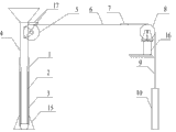
Fig. 1 is the structural representation (when not irritating sand) of the present invention when not irritating sand.
Fig. 2 is the structural representation (when irritating sand) of the present invention when irritating sand.
Fig. 3 is the structural representation of stationary pipes.
Fig. 4 is the structural representation of the moving sleeve pipe of first segment.
Fig. 5 is the structural representation of the moving sleeve pipe of second joint.
Among the figure, 1 is stationary pipes, and 2 are the moving sleeve pipe of first segment, and 3 is the moving sleeve pipe of second joint; 4 for irritating sand hopper, and 5 is double-stranded wheel, and 6 is double-stranded, and 7 is towing plate; 8 are the strand wheel, and 9 is strand, and 10 is counterweight; 11 is outer back-up ring, and 12 is inner shield ring, and 13 is hanger; 14 is reverse horn mouth, and 15 is protective cover, and 16 is support; 17 is support plate, and 18 is ladle, and 19 is the mouth of a river.
The specific embodiment
Below in conjunction with embodiment the present invention is described in further detail.
As shown in Figure 1, irritate drainage sand device and comprise telescopic sleeve pipe, be fixed on the filling sand hopper 4 on the support plate 17, support 16, telescopic sleeve pipe by stationary pipes 1, be placed in the outer moving sleeve pipe 2 of first segment of stationary pipes 1, be placed in the moving sleeve pipe 2 outer moving sleeve pipes 3 of second joint of first segment and form; Stationary pipes 1 upper end is provided with irritates sand hopper 4; Support plate 17 is fixed on to irritate and sands flat on the platform, hangs a pair of sprocket wheel 5 on it; One end of the two strands 6 of double-stranded wheel 5 and a side of towing plate 7 are connected, and the other end is connected on the hanger 13 of the moving sleeve pipe 3 symmetrical both sides suitable for reading of second joint, and the opposite side of towing plate 7 is connected with the strand 9 that is fixed on the strand wheel 8 on the support; Strand 9 lower ends connect counterweight 10.
Fig. 3, Fig. 4, Fig. 5 are respectively stationary pipes 1, first segment moves sleeve pipe 2, moving sleeve pipe 3 structural representations of second joint, stationary pipes 1 is suitable for reading integrally welded with the end opening of irritating sand hopper 4, stationary pipes 1 end opening is provided with an outer back-up ring 11 outward, be provided with an inner shield ring 12 in the moving sleeve pipe of corresponding first segment 2 is suitable for reading, do not break away from stationary pipes 1 all the time to guarantee the moving sleeve pipe of first segment.Moving sleeve pipe 3 hangers 13 that are arranged with suitable for reading of second joint, be connected with two strands 6, can guarantee telescopic sleeve pipe center of gravity non-migration, thereby satisfy the moving sleeve pipe 3 decline accurate positionings of second joint, and be provided with concentric reducer's (indicating among the figure) at moving sleeve pipe 3 end openings of second joint, both can drive the moving sleeve pipe 2 of first segment and rise, not be scattered in the time of can making drainage sand flow outlet spout again; And also be provided with reverse horn mouth 14 existing together, be used to irritate the metal that directly drops into very active very easily oxidization burning loss behind the sand (as titanium close, rare earth), the protection drainage sand and the mouth of a river.The moving sleeve pipe 3 of moving sleeve pipe 2 to the second joints of first segment is in light weight, and it is less to load in the time of can making artificial traction.Second joint is provided with drainage sand protective cover 15 outside moving sleeve pipe 3 bottoms, can avoid the waste of drainage sand.
As shown in Figure 2, when irritating drainage sand, telescopic sleeve pipe stretches, two strands 6 on the two strands wheel 5 is also along with decline, counterweight 10 rises, and when the moving sleeve pipe 3 of second joint was stretched to the mouth of a river 19 of ladle 18 bottoms, drainage sand slowly slipped in the ladle nozzle 19, after needed sand adds, manually draw counterweight 10, make counterweight 10 descend, drive moving of strand 9 and double-stranded 6, thereby with moving sleeve pipe 3 pull-ups of second joint, return to gradually more as shown in Figure 1 do not add sand the time state.
This specific embodiment only is an explanation of the invention; it is not a limitation of the present invention; those skilled in the art can make any modification to present embodiment as required after reading this specification, but as long as all are subjected to the protection of Patent Law in claim scope of the present invention.
Claims (8)
1. irritate drainage sand device, comprise telescopic sleeve pipe, be fixed on the filling sand hopper (4) on the support plate (17), support (16), it is characterized in that: telescopic sleeve pipe by stationary pipes (1), be placed in the moving sleeve pipe (2) of the outer first segment of stationary pipes (1), be placed in the outer moving sleeve pipe (3) of second joint of the moving sleeve pipe (2) of first segment and form, described stationary pipes (1) upper end is provided with filling sand hopper (4);
Described support plate (17) is fixed on to irritate and sands flat on the platform, hangs a pair of sprocket wheel (5) on it; Set firmly strand wheel (8) on the described support (16);
Moving sleeve pipe (3) hanger (13) that is arranged with suitable for reading of described second joint; Described hanger (13) is connected with two strands (6) one ends of double-stranded wheel (5), one side of double-stranded (6) other end and towing plate (7) is connected, the strand (9) of the opposite side of towing plate (7) and strand wheel (8) is connected, and strand (9) lower end connects counterweight (10).
2. filling drainage sand device according to claim 1 is characterized in that: described second joint is provided with drainage sand protective cover (15) outside moving sleeve pipe (3) bottom.
3. filling drainage sand device according to claim 1 is characterized in that: described stationary pipes (1) is suitable for reading integrally welded with the end opening of irritating sand hopper (4).
4. filling drainage sand device according to claim 1 is characterized in that: described stationary pipes (1) end opening is provided with an outer back-up ring (11) outward.
5. filling drainage sand device according to claim 1 is characterized in that: described first segment move sleeve pipe (2) be provided with in suitable for reading one with the corresponding inner shield ring of outer back-up ring (11) (12).
6. filling drainage sand device according to claim 1 is characterized in that: moving sleeve pipe (3) end opening of described second joint is provided with concentric reducer and reverse horn mouth (14).
7. filling drainage sand device according to claim 1 is characterized in that: described first segment moves sleeve pipe (2) and moves the in light weight of sleeve pipe (3) than described second joint.
8. filling drainage sand device according to claim 1, it is characterized in that: the height of described filling sand hopper (4) is 0.5m ~ 1.0m.
Priority Applications (1)
| Application Number | Priority Date | Filing Date | Title |
|---|---|---|---|
| CN 201110200700 CN102248140B (en) | 2011-07-18 | 2011-07-18 | Drainage flowing sand device |
Applications Claiming Priority (1)
| Application Number | Priority Date | Filing Date | Title |
|---|---|---|---|
| CN 201110200700 CN102248140B (en) | 2011-07-18 | 2011-07-18 | Drainage flowing sand device |
Publications (2)
| Publication Number | Publication Date |
|---|---|
| CN102248140A true CN102248140A (en) | 2011-11-23 |
| CN102248140B CN102248140B (en) | 2012-12-19 |
Family
ID=44975915
Family Applications (1)
| Application Number | Title | Priority Date | Filing Date |
|---|---|---|---|
| CN 201110200700 Active CN102248140B (en) | 2011-07-18 | 2011-07-18 | Drainage flowing sand device |
Country Status (1)
| Country | Link |
|---|---|
| CN (1) | CN102248140B (en) |
Cited By (2)
| Publication number | Priority date | Publication date | Assignee | Title |
|---|---|---|---|---|
| CN103551558A (en) * | 2013-10-25 | 2014-02-05 | 中冶南方工程技术有限公司 | Slide gate sanding device |
| CN107999734A (en) * | 2018-01-17 | 2018-05-08 | 北京首钢国际工程技术有限公司 | A kind of ladle nozzle fills sand system |
Citations (6)
| Publication number | Priority date | Publication date | Assignee | Title |
|---|---|---|---|---|
| US3464482A (en) * | 1965-07-23 | 1969-09-02 | United Eng Foundry Co | Continuous casting |
| CN2327477Y (en) * | 1998-04-29 | 1999-07-07 | 宝山钢铁(集团)公司 | Automatic feeder for drain materials for ladles |
| CN101559488A (en) * | 2009-06-02 | 2009-10-21 | 史日霞 | Automatic sand filling device and sand filling method thereof |
| CN201558952U (en) * | 2009-12-23 | 2010-08-25 | 河南省耕生耐火材料有限公司 | Device for launching stuffing sand into steel ladle |
| CN201558939U (en) * | 2009-11-25 | 2010-08-25 | 山西太钢不锈钢股份有限公司 | Stuffing sand adding device |
| CN202155494U (en) * | 2011-07-18 | 2012-03-07 | 永兴特种不锈钢股份有限公司 | Stuffing sand pouring device |
-
2011
- 2011-07-18 CN CN 201110200700 patent/CN102248140B/en active Active
Patent Citations (6)
| Publication number | Priority date | Publication date | Assignee | Title |
|---|---|---|---|---|
| US3464482A (en) * | 1965-07-23 | 1969-09-02 | United Eng Foundry Co | Continuous casting |
| CN2327477Y (en) * | 1998-04-29 | 1999-07-07 | 宝山钢铁(集团)公司 | Automatic feeder for drain materials for ladles |
| CN101559488A (en) * | 2009-06-02 | 2009-10-21 | 史日霞 | Automatic sand filling device and sand filling method thereof |
| CN201558939U (en) * | 2009-11-25 | 2010-08-25 | 山西太钢不锈钢股份有限公司 | Stuffing sand adding device |
| CN201558952U (en) * | 2009-12-23 | 2010-08-25 | 河南省耕生耐火材料有限公司 | Device for launching stuffing sand into steel ladle |
| CN202155494U (en) * | 2011-07-18 | 2012-03-07 | 永兴特种不锈钢股份有限公司 | Stuffing sand pouring device |
Cited By (3)
| Publication number | Priority date | Publication date | Assignee | Title |
|---|---|---|---|---|
| CN103551558A (en) * | 2013-10-25 | 2014-02-05 | 中冶南方工程技术有限公司 | Slide gate sanding device |
| CN103551558B (en) * | 2013-10-25 | 2015-11-18 | 中冶南方工程技术有限公司 | A kind of slide gate nozzle sanding device |
| CN107999734A (en) * | 2018-01-17 | 2018-05-08 | 北京首钢国际工程技术有限公司 | A kind of ladle nozzle fills sand system |
Also Published As
| Publication number | Publication date |
|---|---|
| CN102248140B (en) | 2012-12-19 |
Similar Documents
| Publication | Publication Date | Title |
|---|---|---|
| CN202155494U (en) | Stuffing sand pouring device | |
| CN102248140B (en) | Drainage flowing sand device | |
| CN101575067A (en) | Special hoisting tool with heat-preservation cover for hot metal charging in traveling crane | |
| CN101559488B (en) | Automatic sand filling device and sand filling method thereof | |
| CN202427936U (en) | Spheriodized ladle | |
| CN208843341U (en) | Steel scrap entrucking lifting finger | |
| CN111715873A (en) | Funnel type drainage sand adding device | |
| CN113046517A (en) | Safe and environment-friendly scrap steel adding device for blast furnace hot-metal bottle | |
| CN201752757U (en) | Ladle filler sand slinging machine capable of stably slinging sand | |
| CN215050459U (en) | Iron alloy converter | |
| CN205633932U (en) | Ferroalloy transport of raw materials mechanism | |
| CN208933972U (en) | A kind of concrete-spouting plant | |
| CN215050470U (en) | Safe and environment-friendly scrap steel adding device for blast furnace hot-metal bottle | |
| CN211386891U (en) | Sand filling device for ladle nozzle | |
| CN200995129Y (en) | Cylindrical dog device | |
| CN206705519U (en) | A kind of rectilinear sensing pre-heating device | |
| CN202114248U (en) | Steel ladle filler sand feeding device | |
| CN108889935B (en) | Portable steel slag tank lifting and tipping device | |
| CN204262344U (en) | A kind of ladle draining sand mozzle | |
| CN201940599U (en) | Drainage device for steel making | |
| CN105775968B (en) | A kind of elevator car top structure and lift car | |
| CN2356784Y (en) | Drainage device for smelting steel | |
| CN217474842U (en) | Device for filling drainage sand into steel-making ladle | |
| CN201705356U (en) | High-drop concrete pouring device | |
| CN206143233U (en) | Incomplete iron of blast furnace tap drain discharges structure |
Legal Events
| Date | Code | Title | Description |
|---|---|---|---|
| C06 | Publication | ||
| PB01 | Publication | ||
| C10 | Entry into substantive examination | ||
| SE01 | Entry into force of request for substantive examination | ||
| C14 | Grant of patent or utility model | ||
| GR01 | Patent grant | ||
| CP01 | Change in the name or title of a patent holder | ||
| CP01 | Change in the name or title of a patent holder |
Address after: 313005, Huzhou Economic Development Zone, Zhejiang Province Yang Port Industrial Zone Patentee after: Yongxing special material technology Co., Ltd Address before: 313005, Huzhou Economic Development Zone, Zhejiang Province Yang Port Industrial Zone Patentee before: Yongxing Special Stainless Steel Co., Ltd. |