CN102246084B - Diffractive head-up display device provided with a device for adjusting the position of the virtual image - Google Patents
Diffractive head-up display device provided with a device for adjusting the position of the virtual image Download PDFInfo
- Publication number
- CN102246084B CN102246084B CN2009801491313A CN200980149131A CN102246084B CN 102246084 B CN102246084 B CN 102246084B CN 2009801491313 A CN2009801491313 A CN 2009801491313A CN 200980149131 A CN200980149131 A CN 200980149131A CN 102246084 B CN102246084 B CN 102246084B
- Authority
- CN
- China
- Prior art keywords
- display
- diffraction
- display device
- light beam
- combiner
- Prior art date
- Legal status (The legal status is an assumption and is not a legal conclusion. Google has not performed a legal analysis and makes no representation as to the accuracy of the status listed.)
- Active
Links
Images
Classifications
-
- G—PHYSICS
- G02—OPTICS
- G02B—OPTICAL ELEMENTS, SYSTEMS OR APPARATUS
- G02B27/00—Optical systems or apparatus not provided for by any of the groups G02B1/00 - G02B26/00, G02B30/00
- G02B27/01—Head-up displays
- G02B27/0101—Head-up displays characterised by optical features
-
- G—PHYSICS
- G03—PHOTOGRAPHY; CINEMATOGRAPHY; ANALOGOUS TECHNIQUES USING WAVES OTHER THAN OPTICAL WAVES; ELECTROGRAPHY; HOLOGRAPHY
- G03B—APPARATUS OR ARRANGEMENTS FOR TAKING PHOTOGRAPHS OR FOR PROJECTING OR VIEWING THEM; APPARATUS OR ARRANGEMENTS EMPLOYING ANALOGOUS TECHNIQUES USING WAVES OTHER THAN OPTICAL WAVES; ACCESSORIES THEREFOR
- G03B21/00—Projectors or projection-type viewers; Accessories therefor
- G03B21/14—Details
- G03B21/142—Adjusting of projection optics
-
- G—PHYSICS
- G03—PHOTOGRAPHY; CINEMATOGRAPHY; ANALOGOUS TECHNIQUES USING WAVES OTHER THAN OPTICAL WAVES; ELECTROGRAPHY; HOLOGRAPHY
- G03B—APPARATUS OR ARRANGEMENTS FOR TAKING PHOTOGRAPHS OR FOR PROJECTING OR VIEWING THEM; APPARATUS OR ARRANGEMENTS EMPLOYING ANALOGOUS TECHNIQUES USING WAVES OTHER THAN OPTICAL WAVES; ACCESSORIES THEREFOR
- G03B21/00—Projectors or projection-type viewers; Accessories therefor
- G03B21/14—Details
- G03B21/28—Reflectors in projection beam
-
- G—PHYSICS
- G02—OPTICS
- G02B—OPTICAL ELEMENTS, SYSTEMS OR APPARATUS
- G02B27/00—Optical systems or apparatus not provided for by any of the groups G02B1/00 - G02B26/00, G02B30/00
- G02B27/01—Head-up displays
- G02B27/0101—Head-up displays characterised by optical features
- G02B2027/0123—Head-up displays characterised by optical features comprising devices increasing the field of view
-
- G—PHYSICS
- G02—OPTICS
- G02B—OPTICAL ELEMENTS, SYSTEMS OR APPARATUS
- G02B27/00—Optical systems or apparatus not provided for by any of the groups G02B1/00 - G02B26/00, G02B30/00
- G02B27/01—Head-up displays
- G02B27/0149—Head-up displays characterised by mechanical features
- G02B2027/0154—Head-up displays characterised by mechanical features with movable elements
- G02B2027/0159—Head-up displays characterised by mechanical features with movable elements with mechanical means other than scaning means for positioning the whole image
-
- G—PHYSICS
- G03—PHOTOGRAPHY; CINEMATOGRAPHY; ANALOGOUS TECHNIQUES USING WAVES OTHER THAN OPTICAL WAVES; ELECTROGRAPHY; HOLOGRAPHY
- G03B—APPARATUS OR ARRANGEMENTS FOR TAKING PHOTOGRAPHS OR FOR PROJECTING OR VIEWING THEM; APPARATUS OR ARRANGEMENTS EMPLOYING ANALOGOUS TECHNIQUES USING WAVES OTHER THAN OPTICAL WAVES; ACCESSORIES THEREFOR
- G03B21/00—Projectors or projection-type viewers; Accessories therefor
- G03B21/54—Accessories
- G03B21/56—Projection screens
- G03B21/60—Projection screens characterised by the nature of the surface
- G03B21/62—Translucent screens
-
- G—PHYSICS
- G03—PHOTOGRAPHY; CINEMATOGRAPHY; ANALOGOUS TECHNIQUES USING WAVES OTHER THAN OPTICAL WAVES; ELECTROGRAPHY; HOLOGRAPHY
- G03B—APPARATUS OR ARRANGEMENTS FOR TAKING PHOTOGRAPHS OR FOR PROJECTING OR VIEWING THEM; APPARATUS OR ARRANGEMENTS EMPLOYING ANALOGOUS TECHNIQUES USING WAVES OTHER THAN OPTICAL WAVES; ACCESSORIES THEREFOR
- G03B3/00—Focusing arrangements of general interest for cameras, projectors or printers
- G03B3/04—Focusing arrangements of general interest for cameras, projectors or printers adjusting position of image plane without moving lens
Abstract
The invention relates to a diffractive head-up display device comprising a projection unit generating a light beam to be directed towards a diffractive combiner, the projection unit comprising a light source generating a projection light beam directed towards a display element for forming a source image transmitted towards the diffractive combiner. The device is characterised in that the projection unit comprises a projection mask arranged after the display element and provided with a projection window, the area of said window generally corresponding to the display area of the display element. The device is also characterised in that the light beam lights up an area larger than the display area, in a uniform manner, on the display element, and in that the display element and the mask are mobile in a translational manner, in at least one direction generally orthogonal to the axis of the projection light beam, in such a way that the adjustment of the position of the virtual image in the field of vision of the observer, for example the driver of a vehicle, is obtained by the translation of the display element and the mask.
Description
Technical field
The present invention relates to a kind of being provided with for the diffraction of the equipment of regulating the virtual image position and look squarely (head up) display device.
Background technology
In looking squarely Presentation Function, virtual image is placed in driver's the visual field, thereby considers the ellipse of actual scene and driver's eyes.Yet, be necessary and can regulate its position so that it adapts to the framework of the height of operating seat, his height and the vehicles around the nominal position of virtual image better.
To use a series of mirrors in the head-up display device on basis, regulate the virtual graph the position of image by rotating (perhaps a plurality of) mirror around axle.This solution uses the diffractive head-up display device of diffractive part in the situation that there is no mirror, particularly when making the diffraction combiner by the following process that is used for recording diffraction element and inapplicable, this process for definite illumination angle of combiner wittingly the fixing virtual image that is produced by display device to downwards angle of visibility.
Summary of the invention
The present invention is intended to propose a kind ofly need not to be shifted or the pivot rotational mirror just can be worked is provided with diffractive head-up display device for the equipment of regulating the virtual image position.
for this reason, the present invention proposes a kind of head-up display device, this equipment comprises the projecting cell that produces light beam, this light beam is drawn towards the diffraction combiner, this diffraction combiner is provided in observer's the visual field and forms virtual image, this projecting cell comprises the light source that produces projected light beam, this projected light beam is drawn towards the display that is intended to form the source images that is transferred to the diffraction combiner, it is characterized in that the following fact: projecting cell comprises the projection print plate that is arranged in display afterwards and is provided with projection window, the zone of this projection window is substantially corresponding to the viewing area of display, it is characterized in that the following fact: at the display place, the zone that the homogenizer irradiation is larger than the viewing area, and it is characterized in that the following fact: but display and mask with the axle of projected light beam substantially on rectangular at least one direction translation move, thereby regulate the position of virtual image in the observer visual field of (as vehicle driving person) by the translation of display and mask.
Solution of the present invention moves and the specific projection window based on the translation of display.
According to another feature of the present invention:
-make the diffraction combiner with the form of transparent panel, this transparent panel is provided with a series of diffraction optical elements that are arranged in the surface on individual layer, and wherein for the illumination angle of determining when making the diffraction combiner wittingly fixedly virtual image to downwards angle of visibility;
-by forming the diffraction combiner from die marks or injection, described mould obtains from the record of embossment (relief) shape diffraction structure, this diffraction structure comprises interference fringe, and interference fringe itself is by obtaining by two interfering beam exposure photoresist layers;
-mask is fixed in the output face of display;
-display is liquid crystal display;
-diffraction display device comprises the opertaing device of the position of control display device and mask.
Description of drawings
Other features, objects and advantages of the present invention become apparent in the time of describing in detail below reading with reference to the accompanying drawing that provides as nonrestrictive example, and in accompanying drawing:
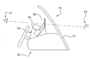
-Fig. 1 shows the schematic diagram of the passenger space of automotive, and what these vehicles were provided with according to the present invention instruction looks squarely the diffraction display device;
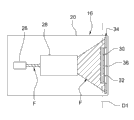
-Fig. 2 schematically shows projecting cell that the diffraction display device of Fig. 1 is provided with and the axial, cross-sectional view of diffraction combiner;
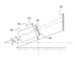
But-Fig. 3 is the axial, cross-sectional view that schematically shows according to the projecting cell of Fig. 1 that is provided with the display that translation moves of the present invention;
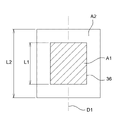
-Fig. 4 shows the irradiation area of projecting cell of Fig. 1 and the figure of viewing area;
-Fig. 5 shows translation direction and the similar view of view Fig. 2 of the display of Fig. 3;
-Fig. 6 shows the figure as the diffraction efficiency of the combiner of Fig. 2 of the function of illumination angle α;
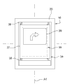
-Fig. 7 is the front view of output that schematically shows the projecting cell of Fig. 1;
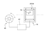
-Fig. 8 shows the figure of control system of the projecting cell of Fig. 1.
Embodiment
In the remainder of instructions, identical or similar components will be represented by same numeral.
Fig. 1 schematically shows the inside of automotive 10, and these vehicles comprise instrument panel 12 and the diffractive head-up display device 14 that forms according to instruction of the present invention.According to illustrated embodiment, diffractive head-up display device 14 is being arranged on instrument panel 12 near windscreen 15.
Diffractive head-up display device 14 according to the present invention comprises projecting cell 16 and hologram device 18, and this hologram device is arranged in the optical axis of driver C and is provided for operation or the driving information that virtual image 19 these forms that are positioned windscreen 15 fronts with the visual field at driver C show the vehicles.
According to the example embodiment that specifically illustrates in Fig. 2 and Fig. 3, projecting cell 16 is assemblied in shell 20 inside.Shell 20 comprises light source 26, and this light source is preferably the laser diode of emission in visible, and this light source produces light beam F, this light beam before display 30 diffusions that form source images by 28 shapings of optical shaping element.Display 30 is for example liquid crystal display.Optical shaping element 28 is intended to produce following light beam F, and the form fit of the shape of this light beam and display 30 and its cross section are the function of the control interval of virtual image.Display 30 is configured to produce source images, and this source images illustrates operation or the driving information of the vehicles.Display 30 is provided preferably with optical diffusion layer 32.
According to illustrated embodiment, hologram device 18 is the diffraction combiners by reflecting to operate.Diffraction combiner 18 is arranged in to make in the visual field of driver C through 18 refractions of diffraction combiner and is positioned at the virtual image 19 of vehicles front with generation from the light beam F of source images.Advantageously, diffraction combiner 18 is the Transparent Parts that comprise diffraction optical element.Diffraction optical element is configured to holographic virtual image 19 is positioned set a distance place really, vehicles fronts, and they also are arranged to the function of amplifying source images.
According to instruction of the present invention, projecting cell 16 comprises the projection print plate 34 that is arranged in display 30 afterwards and is provided with projection window 36, and the zone of this projection window is substantially corresponding to the viewing area of display 30, and this window is shifted by translation.As shown in Fig. 3 and Fig. 4, at display 30 places, the regional A2 that light beam F uniform irradiation is larger than viewing area A1.As shown in Figure 5, but display 30 and mask 34 move with respect to shell 20 translations on rectangular direction D1 substantially at the axle X1 with projected light beam.Direction D1 is contained in basically vertical plane here.Therefore, obtain adjusting to the position of virtual image 19 in the visual field of driver C by the translation together with its projection window 36 of display 30 and mask 34.
As shown in Figure 2, by diffraction combiner 18 by to downwards angle of visibility
β ivAnd distance
d ivBe defined in the virtual image 19 in the visual field of driver C.Bragg's law is according to the following formula with the illumination angle α corresponding with position, angle projected angle 16 combiner 18 and to downwards angle of visibility
β ivRelated:

Wherein:
λ: light wavelength
D: the pitch of the diffraction grating of combiner
As indicated previously, can be write as following formula:
(||)

Therefore, by changing the value of α, can change to downwards angle of visibility β
ivValue.
The present invention allows to change by the position that changes display/mask assembly the position of virtual image 19.
Difference in height L2-L1 between irradiation area A2 and viewing area A1 is corresponding to for angle changing α and therefore angle changing β
ivThe essential translation length with the position that allows adjusting virtual image 19.
Fig. 5 shows the translation direction D1 of display 30 in the shell of projecting cell 16.The shell 20 of display 30 translation and projecting cell on direction D1 and combiner 18 keep fixing.This translation is moved around the central value α corresponding with the initial configuration (nominal position of virtual image) of diffraction display device 14
0The value of angle changing α.
As shown in Figure 6, the change interval of angle [alpha] must be observed the diffraction efficiency curve of combiner 18.
As shown in Figure 7, only guarantee that around the main body 37 of the mask 34 of window 36 display 30 device 18 that is combined sees.Mechanical system 38(is as screw-nut system) provide display 30 around the translation displacement such as initial position as shown in Fig. 7.Mask 34 is preferably made by resilient material and is fixed in the output face of display 30 in order to cover the unused portion of irradiation spot 39.
The people of the translation that as shown in Figure 8, driver C can be by being provided for control display device 30 and mask 34/machine interface 40 and electronic control unit 42 are regulated the position of virtual images 19.
Advantageously, the present invention is particularly suitable for looking squarely diffraction display device 14, and this equipment comprises the diffraction combiner 18 that obtains by the manufacture process that is realized by the laser interference nano-photoetching.Such process preferably includes following steps:
A/ is the uniform photoresist layer of deposit thickness on the flat surfaces of solid substrate;
B/ is the interference fringe of exposing on photoresist layer due to the interference of two light beams that come self-excitation light source;
C/ applies the chemical etching material to photoresist layer and reaches relief variation and the establishment matrix of scheduled time slot interference fringe is transformed into photoresist layer;
D/ is the deposit conductive layer on relief surface;
E/ uses the electroforming process to obtain mould to conducting stratum; And
Thereby f/ uses described mould to shift the diffraction embossment structure from substrate to homogeneous transparent plastic element and forms the diffraction combiner.
Advantageously, step b/ is by two light beams realizations, wherein the angle θ between two light beams from the same laser source
iEqual:

One of interfering beam is dispersed and is presented spherical wave front, and another interfering beam is plane wave, and their interference generates the variable diffraction grating of pitch with curved stripes outline line.
In fact, thus the first step of this process comprises that create being used for the matrix that follow-up mould makes allows large-scale production.The substrate that this matrix is made by rigid material forms, and the photoresist layer of the wavelength sensitive of lasing light emitter used is deposited on this substrate, and this lasing light emitter used is always identical, only is modified in two angles light beam from a step to another step.
Routinely, send two light beams from identical sources on the flat surfaces of photoresist layer, thereby produce interference fringe on whole exposure surface.The existence of these interference causes the variable exposure on the surface of photosensitive layer, and then this photosensitive layer stands the processing of chemical substance, and described chemical substance has the character according to its depth of exposure dissolved material.
Interference fringe is transformed into the variation of embossment after some part of dissolving photoresist layer, with regard to this meaning, therefore produces chemical etching.
Exposure (for one of two light beams) in a plurality of angles causes being manufactured on the combiner that the surface has multiplexing grating in this case, the different colours that this combiner can recover not superpose according to the incident beam from the projector equipment of distinguishing the different colours district.
Then, to relief surface deposition of thin conducting stratum, thereby allow the follow-up electroforming process that applies to obtain mould.Then the latter is used for by large-scale production means (as impression or inject), diffraction structure being transformed into embossment on the transparent plastic element.Therefore might obtain the single layer combination device made by transparent plastic, its diffraction structure is etched on the surface and in fact is the relief surface diffraction grating.
Obtaining the embossment permission on matrix by the degree of depth of controlling simply the embossment on matrix surface, the diffraction efficiency of especially controlling final combiner by regulating the chemical etching time by chemical etching.This is lip-deep another major advantage that of the present invention and diffraction grating is present in transparent substrates: illumination only depends on diffraction efficiency and does not rely on selected materials or its refractive index.
At last, the combiner that process of the present invention allows acquisition to be made by transparent plastic material with smooth this form of plastic plate of outward appearance, one of surface of this plastic plate comprises diffraction structure, this permission is carried out transmission and reflective operation with different refraction efficient.Reflection for example is integrated in windscreen corresponding to combiner.
Claims (7)
1. a diffractive head-up display device (14), comprise the projecting cell (16) that produces light beam, described light beam is drawn towards diffraction combiner (18), described diffraction combiner (18) is provided for and forms virtual image (19) in observer's the visual field, described projecting cell (16) comprises the light source (26) that produces projected light beam, described projected light beam is drawn towards the display (30) that is intended to form the source images that is transferred to described diffraction combiner (18), it is characterized in that: described projecting cell (16) comprises the projection print plate (34) that is arranged in described display (30) afterwards and is provided with projection window (36), the zone of described projection window (36) is substantially corresponding to the viewing area of described display (30), locate at described display (30), described homogenizer shines the zone larger than described viewing area, and, described display (30) and described projection print plate (34) but with the axle of described projected light beam substantially on rectangular at least one direction translation move, thereby the translation by described display (30) and described projection print plate (34) obtains the adjusting to the position of described virtual image (19) in described observer's the visual field.
2. diffractive head-up display device as claimed in claim 1 (14), it is characterized in that: the form with transparent panel is made diffraction combiner (18), this transparent panel is provided with a series of diffraction optical elements that are arranged in the surface on individual layer, and wherein for the illumination angle (α) of determining when making diffraction combiner (18) wittingly fixedly virtual image (19) to downwards angle of visibility (β
iv).
3. diffractive head-up display device as claimed in claim 1 (14), wherein said observer is vehicle driving person.
4. diffractive head-up display device as claimed in claim 1 or 2 (14), it is characterized in that: by forming diffraction combiner (18) from die marks or injection, described mould obtains from the record of embossment shape diffraction structure, this diffraction structure comprises interference fringe, and interference fringe itself is by obtaining by two interfering beam exposure photoresist layers.
5. diffractive head-up display device as claimed in claim 1 or 2 (14), it is characterized in that: described projection print plate (34) is fixed in the output face of described display (30).
6. diffractive head-up display device as claimed in claim 1 or 2 (14) is characterized in that: described display (30) is liquid crystal display.
7. diffractive head-up display device as claimed in claim 1 or 2 (14) is characterized in that: it comprises the opertaing device (42) of the position of controlling described display (30) and described projection print plate (34).
Applications Claiming Priority (5)
| Application Number | Priority Date | Filing Date | Title |
|---|---|---|---|
| EP08171139.2 | 2008-12-09 | ||
| EP08171139 | 2008-12-09 | ||
| EP08171134.3 | 2008-12-09 | ||
| EP08171134 | 2008-12-09 | ||
| PCT/EP2009/066758 WO2010066804A1 (en) | 2008-12-09 | 2009-12-09 | Diffractive head-up display device provided with a device for adjusting the position of the virtual image |
Publications (2)
| Publication Number | Publication Date |
|---|---|
| CN102246084A CN102246084A (en) | 2011-11-16 |
| CN102246084B true CN102246084B (en) | 2013-05-08 |
Family
ID=41698352
Family Applications (1)
| Application Number | Title | Priority Date | Filing Date |
|---|---|---|---|
| CN2009801491313A Active CN102246084B (en) | 2008-12-09 | 2009-12-09 | Diffractive head-up display device provided with a device for adjusting the position of the virtual image |
Country Status (5)
| Country | Link |
|---|---|
| US (1) | US8351123B2 (en) |
| EP (1) | EP2376968B1 (en) |
| JP (1) | JP5542836B2 (en) |
| CN (1) | CN102246084B (en) |
| WO (1) | WO2010066804A1 (en) |
Families Citing this family (15)
| Publication number | Priority date | Publication date | Assignee | Title |
|---|---|---|---|---|
| FR2962815B1 (en) * | 2010-07-16 | 2013-06-21 | Delphi Tech Inc | HEIGHT ADJUSTABLE HEAD DISPLAY DEVICE |
| JP5732939B2 (en) * | 2011-03-16 | 2015-06-10 | セイコーエプソン株式会社 | prompter |
| TWI446001B (en) * | 2011-10-04 | 2014-07-21 | Automotive Res & Testing Ct | Multi-optical head development device |
| DE102012010889A1 (en) * | 2012-06-01 | 2013-12-05 | Audi Ag | Method and device for aligning a head-up display projector |
| JP5871739B2 (en) * | 2012-07-25 | 2016-03-01 | カルソニックカンセイ株式会社 | Vehicle display device |
| KR20140134184A (en) | 2013-05-13 | 2014-11-21 | 삼성디스플레이 주식회사 | Head-up display system and method and apparatus for controlling the same |
| TW201520673A (en) | 2013-11-26 | 2015-06-01 | Automotive Res & Testing Ct | Information display system with automatic viewable range adjustment and display method thereof |
| US9995933B2 (en) | 2014-06-24 | 2018-06-12 | Microsoft Technology Licensing, Llc | Display devices with transmittance compensation mask |
| FR3029648B1 (en) * | 2014-12-05 | 2018-02-02 | Valeo Comfort And Driving Assistance | HEAD-UP DISPLAY WITH ADJUSTABLE VIEW-WINDOW |
| EP3076222A1 (en) * | 2015-04-02 | 2016-10-05 | Continental Automotive GmbH | Head-up display |
| KR20170014497A (en) * | 2015-07-30 | 2017-02-08 | 주식회사 코리아하이텍 | Projector display device for using vehicle |
| CN105892057B (en) * | 2016-05-16 | 2018-08-31 | 中国民航大学 | A kind of colored diffraction head-up display of holography based on polymer multilayer film |
| US10134190B2 (en) | 2016-06-14 | 2018-11-20 | Microsoft Technology Licensing, Llc | User-height-based rendering system for augmented reality objects |
| TWI615632B (en) | 2016-10-04 | 2018-02-21 | 財團法人工業技術研究院 | Head-up displaywith variable focal length |
| CN110133801B (en) * | 2019-06-17 | 2021-03-02 | 杭州光粒科技有限公司 | Double-depth imaging method based on polarization photosensitive grating AR (augmented reality) glasses waveguide |
Citations (3)
| Publication number | Priority date | Publication date | Assignee | Title |
|---|---|---|---|---|
| EP0880287A1 (en) * | 1997-05-23 | 1998-11-25 | Barco N.V. | LCD-projector |
| DE102006017666A1 (en) * | 2006-04-12 | 2007-11-08 | Siemens Ag | Display device e.g. head-up display, for motor vehicle, has piezo-motor comprising piezoelectric unit and surface that is connected directly or over grating flange with unit, where position or geometry of image forming device is adjusted |
| EP1862841A1 (en) * | 2006-06-01 | 2007-12-05 | Delphi Technologies, Inc. | Holographic head-up projection device for an automobile |
Family Cites Families (14)
| Publication number | Priority date | Publication date | Assignee | Title |
|---|---|---|---|---|
| US3940204A (en) * | 1975-01-23 | 1976-02-24 | Hughes Aircraft Company | Optical display systems utilizing holographic lenses |
| KR960016721B1 (en) * | 1993-12-23 | 1996-12-20 | 현대전자산업 주식회사 | Vehicle head-up display device for hologram light particle |
| JPH07199115A (en) * | 1993-12-28 | 1995-08-04 | Nissan Motor Co Ltd | Display device |
| JPH08197980A (en) * | 1994-11-25 | 1996-08-06 | Asahi Glass Co Ltd | Holographic display system |
| JP3727078B2 (en) * | 1994-12-02 | 2005-12-14 | 富士通株式会社 | Display device |
| JP3871932B2 (en) * | 2001-12-28 | 2007-01-24 | シャープ株式会社 | Display device and backlight device |
| JP4288494B2 (en) * | 2004-05-10 | 2009-07-01 | 船井電機株式会社 | Monitor device |
| JP4336245B2 (en) * | 2004-05-18 | 2009-09-30 | 矢崎総業株式会社 | Head-up display device |
| FR2900475B1 (en) * | 2006-04-26 | 2008-10-31 | Essilor Int | DISPLAY COMPRISING A PAIR OF BINOCULAR GLASSES AND WITH A DEVICE FOR ADJUSTING THE IMAGE |
| JP4720694B2 (en) * | 2006-09-14 | 2011-07-13 | 株式会社デンソー | Vehicle display device |
| KR20080050669A (en) * | 2006-12-04 | 2008-06-10 | 엘지전자 주식회사 | Head up display apparatus for vehicle |
| GB2461294B (en) * | 2008-06-26 | 2011-04-06 | Light Blue Optics Ltd | Holographic image display systems |
| US8520310B2 (en) * | 2008-09-26 | 2013-08-27 | Konica Minolta Opto, Inc. | Image display device, head-mounted display and head-up display |
| EP2376969B1 (en) * | 2008-12-09 | 2014-03-19 | Delphi Technologies, Inc. | Diffractive combiner for multicolour and monochrome display, production method, and head-up display device using same |
-
2009
- 2009-12-09 CN CN2009801491313A patent/CN102246084B/en active Active
- 2009-12-09 JP JP2011540084A patent/JP5542836B2/en active Active
- 2009-12-09 US US13/133,600 patent/US8351123B2/en active Active
- 2009-12-09 WO PCT/EP2009/066758 patent/WO2010066804A1/en active Application Filing
- 2009-12-09 EP EP09764867A patent/EP2376968B1/en active Active
Patent Citations (3)
| Publication number | Priority date | Publication date | Assignee | Title |
|---|---|---|---|---|
| EP0880287A1 (en) * | 1997-05-23 | 1998-11-25 | Barco N.V. | LCD-projector |
| DE102006017666A1 (en) * | 2006-04-12 | 2007-11-08 | Siemens Ag | Display device e.g. head-up display, for motor vehicle, has piezo-motor comprising piezoelectric unit and surface that is connected directly or over grating flange with unit, where position or geometry of image forming device is adjusted |
| EP1862841A1 (en) * | 2006-06-01 | 2007-12-05 | Delphi Technologies, Inc. | Holographic head-up projection device for an automobile |
Also Published As
| Publication number | Publication date |
|---|---|
| WO2010066804A1 (en) | 2010-06-17 |
| JP5542836B2 (en) | 2014-07-09 |
| US8351123B2 (en) | 2013-01-08 |
| JP2012511738A (en) | 2012-05-24 |
| US20110267701A1 (en) | 2011-11-03 |
| CN102246084A (en) | 2011-11-16 |
| EP2376968A1 (en) | 2011-10-19 |
| EP2376968B1 (en) | 2013-01-16 |
Similar Documents
| Publication | Publication Date | Title |
|---|---|---|
| CN102246084B (en) | Diffractive head-up display device provided with a device for adjusting the position of the virtual image | |
| US11353641B2 (en) | Manufacturing for virtual and augmented reality systems and components | |
| JP2013522667A (en) | Diffraction type combiner for head-up color display | |
| CN102246083B (en) | Diffractive combiner for multicolour and monochrome display, production method, and head-up display device using same | |
| EP3461636B1 (en) | Laminated holographic display and manufacturing thereof | |
| US9285588B2 (en) | See-through display device and vehicle having see-through display device mounted thereon | |
| JP5722998B2 (en) | Head-up display system | |
| CA2976955C (en) | Improved manufacturing for virtual and augmented reality systems and components | |
| CN105204172B (en) | Show that the visual field of image shows equipment for the passenger for vehicle | |
| US20130016410A1 (en) | Optical device for an illumination device of a 3d display | |
| EP2469324A1 (en) | An embossed reflective volume phase grating for a heads up display system diffractive combiner | |
| JP2012511739A5 (en) | ||
| KR101883235B1 (en) | Injection molding method of an outer panel having a hologram for a tail lamp of a car | |
| TWI588628B (en) | Method for producing a holographic optical element | |
| CN114815241B (en) | Head-up display system and method and vehicle-mounted system | |
| CN216622850U (en) | Multi-depth head-up display system and vehicle-mounted system | |
| Zacharovas et al. | New diffractive effects for security holograms produced with Geolas Originators | |
| CN109613810A (en) | A kind of lamp system with three-dimensional stereo effect | |
| CN112764219B (en) | Head-up display system and application thereof | |
| CN214619378U (en) | Holographic automobile tail lamp device with three-dimensional image display function | |
| Redmond | 18‐1: Invited Paper: Holographic Optical Elements for Automotive Windshield Displays | |
| JPH04345537A (en) | Automotive head-up display | |
| JPH10274747A (en) | Holographic display device and production of hologram | |
| JPH0669964U (en) | Holographic display | |
| KR20230115729A (en) | Plane duplicating technology of round holographic optical element |
Legal Events
| Date | Code | Title | Description |
|---|---|---|---|
| C06 | Publication | ||
| PB01 | Publication | ||
| C10 | Entry into substantive examination | ||
| SE01 | Entry into force of request for substantive examination | ||
| C14 | Grant of patent or utility model | ||
| GR01 | Patent grant | ||
| TR01 | Transfer of patent right | ||
| TR01 | Transfer of patent right |
Effective date of registration: 20190214 Address after: Babado J San Michaele Co-patentee after: Univerisity of Strasbourg Patentee after: Amberford Technology Co., Ltd. Address before: Michigan Co-patentee before: Univerisity of Strasbourg Patentee before: Delphi Technology Inc. |