CN102203982A - Alkaline cell with improved separator - Google Patents
Alkaline cell with improved separator Download PDFInfo
- Publication number
- CN102203982A CN102203982A CN2009801439969A CN200980143996A CN102203982A CN 102203982 A CN102203982 A CN 102203982A CN 2009801439969 A CN2009801439969 A CN 2009801439969A CN 200980143996 A CN200980143996 A CN 200980143996A CN 102203982 A CN102203982 A CN 102203982A
- Authority
- CN
- China
- Prior art keywords
- diaphragm
- spacer body
- battery
- coiling
- diaphragms
- Prior art date
- Legal status (The legal status is an assumption and is not a legal conclusion. Google has not performed a legal analysis and makes no representation as to the accuracy of the status listed.)
- Pending
Links
Images


Classifications
-
- H—ELECTRICITY
- H01—ELECTRIC ELEMENTS
- H01M—PROCESSES OR MEANS, e.g. BATTERIES, FOR THE DIRECT CONVERSION OF CHEMICAL ENERGY INTO ELECTRICAL ENERGY
- H01M50/00—Constructional details or processes of manufacture of the non-active parts of electrochemical cells other than fuel cells, e.g. hybrid cells
- H01M50/40—Separators; Membranes; Diaphragms; Spacing elements inside cells
- H01M50/409—Separators, membranes or diaphragms characterised by the material
- H01M50/44—Fibrous material
-
- H—ELECTRICITY
- H01—ELECTRIC ELEMENTS
- H01M—PROCESSES OR MEANS, e.g. BATTERIES, FOR THE DIRECT CONVERSION OF CHEMICAL ENERGY INTO ELECTRICAL ENERGY
- H01M50/00—Constructional details or processes of manufacture of the non-active parts of electrochemical cells other than fuel cells, e.g. hybrid cells
- H01M50/40—Separators; Membranes; Diaphragms; Spacing elements inside cells
- H01M50/409—Separators, membranes or diaphragms characterised by the material
- H01M50/411—Organic material
- H01M50/414—Synthetic resins, e.g. thermoplastics or thermosetting resins
-
- H—ELECTRICITY
- H01—ELECTRIC ELEMENTS
- H01M—PROCESSES OR MEANS, e.g. BATTERIES, FOR THE DIRECT CONVERSION OF CHEMICAL ENERGY INTO ELECTRICAL ENERGY
- H01M50/00—Constructional details or processes of manufacture of the non-active parts of electrochemical cells other than fuel cells, e.g. hybrid cells
- H01M50/40—Separators; Membranes; Diaphragms; Spacing elements inside cells
- H01M50/409—Separators, membranes or diaphragms characterised by the material
- H01M50/411—Organic material
- H01M50/429—Natural polymers
- H01M50/4295—Natural cotton, cellulose or wood
-
- H—ELECTRICITY
- H01—ELECTRIC ELEMENTS
- H01M—PROCESSES OR MEANS, e.g. BATTERIES, FOR THE DIRECT CONVERSION OF CHEMICAL ENERGY INTO ELECTRICAL ENERGY
- H01M50/00—Constructional details or processes of manufacture of the non-active parts of electrochemical cells other than fuel cells, e.g. hybrid cells
- H01M50/40—Separators; Membranes; Diaphragms; Spacing elements inside cells
- H01M50/409—Separators, membranes or diaphragms characterised by the material
- H01M50/449—Separators, membranes or diaphragms characterised by the material having a layered structure
-
- H—ELECTRICITY
- H01—ELECTRIC ELEMENTS
- H01M—PROCESSES OR MEANS, e.g. BATTERIES, FOR THE DIRECT CONVERSION OF CHEMICAL ENERGY INTO ELECTRICAL ENERGY
- H01M50/00—Constructional details or processes of manufacture of the non-active parts of electrochemical cells other than fuel cells, e.g. hybrid cells
- H01M50/40—Separators; Membranes; Diaphragms; Spacing elements inside cells
- H01M50/463—Separators, membranes or diaphragms characterised by their shape
- H01M50/469—Separators, membranes or diaphragms characterised by their shape tubular or cylindrical
-
- H—ELECTRICITY
- H01—ELECTRIC ELEMENTS
- H01M—PROCESSES OR MEANS, e.g. BATTERIES, FOR THE DIRECT CONVERSION OF CHEMICAL ENERGY INTO ELECTRICAL ENERGY
- H01M50/00—Constructional details or processes of manufacture of the non-active parts of electrochemical cells other than fuel cells, e.g. hybrid cells
- H01M50/40—Separators; Membranes; Diaphragms; Spacing elements inside cells
- H01M50/489—Separators, membranes, diaphragms or spacing elements inside the cells, characterised by their physical properties, e.g. swelling degree, hydrophilicity or shut down properties
- H01M50/491—Porosity
-
- H—ELECTRICITY
- H01—ELECTRIC ELEMENTS
- H01M—PROCESSES OR MEANS, e.g. BATTERIES, FOR THE DIRECT CONVERSION OF CHEMICAL ENERGY INTO ELECTRICAL ENERGY
- H01M6/00—Primary cells; Manufacture thereof
- H01M6/04—Cells with aqueous electrolyte
- H01M6/06—Dry cells, i.e. cells wherein the electrolyte is rendered non-fluid
- H01M6/08—Dry cells, i.e. cells wherein the electrolyte is rendered non-fluid with cup-shaped electrodes
- H01M6/085—Dry cells, i.e. cells wherein the electrolyte is rendered non-fluid with cup-shaped electrodes of the reversed type, i.e. anode in the centre
-
- Y—GENERAL TAGGING OF NEW TECHNOLOGICAL DEVELOPMENTS; GENERAL TAGGING OF CROSS-SECTIONAL TECHNOLOGIES SPANNING OVER SEVERAL SECTIONS OF THE IPC; TECHNICAL SUBJECTS COVERED BY FORMER USPC CROSS-REFERENCE ART COLLECTIONS [XRACs] AND DIGESTS
- Y02—TECHNOLOGIES OR APPLICATIONS FOR MITIGATION OR ADAPTATION AGAINST CLIMATE CHANGE
- Y02P—CLIMATE CHANGE MITIGATION TECHNOLOGIES IN THE PRODUCTION OR PROCESSING OF GOODS
- Y02P70/00—Climate change mitigation technologies in the production process for final industrial or consumer products
- Y02P70/50—Manufacturing or production processes characterised by the final manufactured product
Landscapes
- Chemical & Material Sciences (AREA)
- Chemical Kinetics & Catalysis (AREA)
- Electrochemistry (AREA)
- General Chemical & Material Sciences (AREA)
- Engineering & Computer Science (AREA)
- Manufacturing & Machinery (AREA)
- Life Sciences & Earth Sciences (AREA)
- Wood Science & Technology (AREA)
- Primary Cells (AREA)
- Cell Separators (AREA)
Abstract
An alkaline cell with improved separator. The separator is formed of two sheets (130a, 130b). The two sheets are wound into, a tube shape and the bottom edge of the wound separator is folded and heat sealed. The facing surfaces of the two sheets forming the separator body are not glued or bonded together. The two separator sheets may overlap laterally so that a portion of each sheet forms a different portion of the separator outside surface. Alternatively, the separator may be formed of two sheets wherein the first sheet forms an outer layer which completely covers the second sheet. One sheet is preferably composed of a blend of polyvinylalcohol fibers and rayon fibers and the other sheet composed of polyvinylalcohol fibers and wood pulp fibers.
Description
Technical field
The present invention relates to be used for the spacer body of alkaline battery.The present invention relates to alkaline battery, especially have the anode that comprises zinc and comprise the negative electrode of manganese dioxide and the alkaline battery of the spacer body of the improvement between anode and negative electrode.
Background technology
Primary alkaline battery has the dividing plate of the anode that comprises zinc anode active material, the negative electrode that comprises the manganese dioxide cathodes active material, alkaline electrolyte and electrolyte permeable usually.Described spacer body is the non-woven material of individual layer normally, and described non-woven material comprises the blend of cellulose fibre or vinal or cellulose fiber peacekeeping vinal.A kind of spacer body that is generally used for the prior art of alkaline battery can be made of a slice separator material, and described separator material self is reeled to produce dual spacer body layer, and wherein every layer is that same material is formed.The spacer body that is used for the prior art of alkaline battery can have two-layer different material, and it is glued to together.At United States Patent (USP) 4,361, in 632, double-deck spacer body is disclosed, wherein one deck is the coating that comprises polyvinyl alcohol, it adheres on the base portion absorbed layer.
The internal layer that the another kind of double-deck spacer body that is used for alkaline battery can comprise the outer of glassine paper and be made of the blend of non-woven artificial silk and vinal.Usually using polyacrylic acid that cellophane layer is glued to the layer that is made of artificial silk and vinal goes up to prepare the spacer body of double-layer lamination, as United States Patent (USP) 4,902, described in 590.Described cellophane layer has aperture, its be intended to prevent the zinc dendrimer normal battery between the operating period from wherein passing through.If the zinc dendrimer is by spacer body, they can cause battery short circuit.In adopting the double-deck spacer body of glassine paper as the routine of a layer, with described diaphragm gluing each other or bonding be necessary, if because glassine paper very frangible and be not adhered to that another layer goes up will be damaged or rupture.Yet during spacer body was wound into tubular configuration, gluing layer experience was curled.Surface that the spacer body layer faces mutually also has such shortcoming to use glue to bond: glue or other binding material can postpone electrolyte ion and transmit speed by the spacer body main body, and it can reduce the performance of battery in high power applications then.
Have the spacer body that integral layer is pressed onto the compacted zone on the impregnate layer and be disclosed in United States Patent (USP) 6,379, in 836.Prevent alkaline cellulose fibre two-layer all comprising, and it can comprise wood pulp.Described fiber can be used naoh treatment, so that they are not shunk in the presence of alkaline electrolyte.
The spacer body that is used for cylindrical alkaline battery usually can be by preparing with two straight separator material bars of right-angle crossing, therefore at the center of the bar of two intersections lap arranged.(each bar can be made of the individual layer or double-deck aforesaid material.) then can be by the spacer body pipeline is formed in the bar insertion pipeline of two intersections and heat seal bottom (i.e. two parts of having intersected).Heat-sealable side also, thus spacer body pipeline formed with blind end and opposing open end.Such spacer body pipeline can be inserted in the openend of alkaline battery cylindrical housings near the arrangement mode of the inner surface of negative electrode with its outer surface usually.Other method of spacer body that typing is used for alkaline battery for example is described among the U.S 4,669,183 and US 2008/0124621A1.
Described active material of positive electrode comprises and the gelling agent (as carboxymethyl cellulose or acrylic copolymer) of zinc oxide and routine and the zinc granule that electrolyte mixes.Described gelling agent keeps zinc granule in position and contacts with each other.Usually conducting metal nail (being called anode collector) is inserted in the anode material and contact the negative terminal of its formation battery with end cap.Described alkaline electrolyte is the aqueous solution of potassium hydroxide normally, but also can use other alkaline solution of NaOH or lithium hydroxide.
Described cathode material normally the manganese dioxide particle and can comprise a spot of carbon or graphite granule to increase conductivity.Because electrolysis MnO
2(EMD) high density and its can obtain with high-purity with electrolytic method easily, so its preferred manganese dioxide form that is alkaline battery.The graphite granule and the KOH aqueous solution can be added in the manganese dioxide to form cathode mix.This type of mixture forms wet solid mixture, and it can be compacted in the battery container fully.Cathode material can be preformed into dish type and insert annular ring (for example) in the battery, compacting again then as United States Patent (USP) 5,283, shown in 139 to form in the stacked arrangement mode.
Because the commercial battery size fixes, expected the surface area by increasing electrode active material and in battery, attempted the increase capacity, be i.e. battery useful useful life by the more substantial active material of filling.This method has the restriction in the practice.If active material too closely is loaded in the battery, this can reduce the speed of interdischarge interval electrochemical reaction, reduction of service life then.The ill-effect that other can occur is as polarization, especially when high current drain (high power applications).The mobility of polarization limits ion in electrode active material and in electrolyte, it has reduced useful life then.MnO
2Contact resistance between the battery container of active material of cathode and alkaline battery has also reduced useful life.This contact resistance loss increases usually, especially when battery when discharging during the high power applications (between about 0.5 and 1 watt).
There is the preparation of increase better to be applicable to the business demand of the primary alkaline battery of high power applications.Modern electronic devices such as cellular phone, digital camera and toy, portable flash device, remote-control toy, video camera and high-intensity lamp are the examples of this type of high power applications.This type of device need be between about 0.5 and 2 ampere, more generally the high current consumption speed between about 0.5 and 1.5 ampere, the normally current drain of pulse.Correspondingly, they need operated under the power demand between about 0.5 and 2 watt.
When high power applications, when battery uses a period of time, store, and then use, can improve the probability that the zinc dendrimer forms.Determined when battery under high power applications during frequent the use, the alkaline battery separator of routine is not in that to prevent that zinc dendrimer particle from passing aspect the separator material once in a while so effective.When by alkaline electrolyte when wetting, conventional spacer body also is tending towards being swelling to and can surpasses 300 microns usually, or even surpasses about 350 microns thickness.Therefore, thus expectation reduces spacer body thickness provides more battery volume for anode and cathode material.The spacer body that can adapt to the macroion transmitance can also be applicable to the alkaline battery that is used for higher power applications more.In a word, wish to improve spacer body, so that can increase conventional useful useful life of primary alkaline battery, especially for being used for the high power applications battery.
Summary of the invention
The present invention relates to have the alkaline battery of the spacer body of improvement.Described alkaline battery has the anode that comprises zinc, the negative electrode that comprises manganese dioxide and alkaline electrolyte (as aqueous potassium hydroxide) usually.Described alkaline battery can have cylindrical housings (shell) usually, and described cylindrical housings has openend and relative blind end.After adding cell contents, end cap assembly can be curled in position with the closure casing openend.
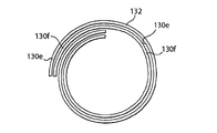
One main aspect, the spacer body that the present invention improves is double-deck spacer body.Spacer body of the present invention is made of two different materials of forming, and described material a slice covers another above sheet and be wound into tubulose.Bottom fold closes and heated sealant with the spacer body of reeling.Not with the remainder of described spacer body (promptly forming the surface that the diaphragm of two coilings of spacer body main body is faced mutually) gummed or in other words bonded to each other each other.Therefore, the diaphragm of facing mutually is chemistry or physical bond and not lamination or glued together each other not, but the bottom by folding and sealing simply a slice cover another and be held in place above sheet.If the blind end of spacer body is cut, two spacer body diaphragms are peeled off easily so.The spacer body of the diaphragm of having determined to form in this way with two overlapping different materials (every the surface of facing mutually do not glue together and do not combine) causes the spacer body that is used for alkaline battery that improves.Specifically, when battery was used for high power applications for example to power supplies such as digital cameras, spacer body of the present invention provided the alkaline battery that has than the long life.
Spacer body of the present invention provides bigger design flexibility, because select each layer from different materials.For example, a slice in the diaphragm can have the macroion transmission characteristic, and it allows that thus excellent electrolytical ion transfer is arranged in high power applications.Yet this type of diaphragm may not be enough rigidity, so that use with the form of individual layer spacer body.Therefore, in continuing design of the present invention, can be to this primary diaphragm with the second spacer body membrane covered of different materials, thus provide bigger rigidity and structural intergrity for the spacer body of reeling.Select two kinds of separator material, so that make the surface combination needs together that two diaphragms are faced mutually become optional.In the present invention, the not combination and not laminated together of surface that two diaphragms are faced mutually.This has reduced by the resistance of spacer body and has improved the electrolyte ion transmission thus, has improved the high rate performance of battery then.
In one aspect, spacer body of the present invention is made of two spacer body diaphragms, and promptly primary diaphragm covers on the secondary diaphragm, and two overlapping diaphragms are wound into tubulose.When observing when laying flat on one's back, every diaphragm has the configuration of rectangle or essentially rectangular.When observing when laying flat on one's back, every diaphragm has a pair of opposing vertical edge (forms leading edge and another formation trailing edge) and a pair of transverse edge (forming top and relative bottom margin).A slice in (described leading edge is the edge that ranks forefront on coiling direction) two diaphragms for example outer or part of the primary diaphragm spacer body of form reeling is outer, and another sheet diaphragm for example secondary diaphragm form the internal layer or the part internal layer of the spacer body of reeling.By being overlapped on another sheet, a slice in two diaphragms forms spacer body.Overlapping diaphragm is placed around mandrel, described mandrel is rotated to form the tubulose spacer body.(place above-mentioned diaphragm leading edge, so that make them on the channeling direction of described mandrel rotation.) bottom margin of the spacer body of reeling is folding and heated sealant is closed, form the open cast of bottom sealing and opposite end.As mentioned above, the surface that two diaphragms forming the spacer body main body are faced does not mutually combine.
A slice in two spacer body diaphragms for example primary diaphragm is formed by the blend of vinal and rayon fiber ideally.(artificial silk is the semisynthetic material that staple fibre constituted that is made of regenerated cellulose or be made of regenerated cellulose, and substituting group has replaced and is no more than contained hydrogen in 15% the cellulose hydroxyl in the described regenerated cellulose.) cellulosic rayon fiber is tending towards absorbed electrolyte, and vinal is hydrophilic to alkaline electrolyte and therefore is easy to by electrolyte wetting.Vinal also provides structural intergrity to spacer body, and does not degrade in the presence of alkaline electrolyte.In described primary diaphragm, vinal can account between about 20% and 80% weight of diaphragm weight, common about 80% weight, and rayon fiber can account between about 80% and 20% weight of diaphragm weight, common about 20% weight.This type of diaphragm that comprises vinal and rayon fiber is preferred, and have ideally between about 30 and 120 microns (dryings) thickness and between about 20 and 40g/m
2Basic weight between (drying), and the porosity between 75% and 85% (pore volume/cumulative volume * 100) (drying).Alternatively, primary diaphragm can be made of 100% cellulosic material, rather than comprises the blend of vinal and rayon fiber.Other the suitable material that is used for primary diaphragm can be 100% polyvinyl alcohol or 100% nylon 66 fiber, but the blend of polyvinyl alcohol and rayon fiber is preferred.
Another sheet (second) spacer body diaphragm is formed by the material that comprises wood pulp and vinal ideally.Described wood pulp (drying) is made of lignocellulose fiber basically, but also can comprise the pulping compound that some is present in the remnants in the timber of handling by chemical pulping method usually.Described wood pulp can be made by trees, and described trees are coniferous trees or have vanelets or the tree of big blade, and preferably made by palohierror.The wood pulp that adopts in the described secondary diaphragm preferably alkalized, i.e. the wood pulp of crossing with naoh treatment, helping to dissolve residue, fortifying fibre, and make fiber more the alkali resistance electrolyte corrode.This type of remaining compound can comprise for example lignin, resin and hemicellulose.The compound of described remnants occupies the dry wood pulp of described (second) spacer body diaphragm usually by weight less than about 3%.Therefore, as used herein, term " wood pulp " is interpreted as dry wood pulp cellulose cellulose fiber, and it comprises the lignocellulose fiber at least about 97% by weight, and residue comprises by weight the residual compounds less than about 3%.
Be used for the wood pulp cellulose of this (second) spacer body diaphragm and the difference of rayon fiber and be that rayon fiber is formed by following material: the regenerated cellulose (cellulosic material of chemical improvement) that the denitration (Chardonette method) by the cellulose nitrate fiber forms, perhaps wherein substituting group has been no more than the regenerated cellulose of about 15% hydrogen, the perhaps regenerated cellulose that forms by adhesive means in the substituted cellulose hydroxyl.This type of renovation process is given physical characteristic, specifically, and the physical characteristic relevant with rayon fiber.Term " regenerated cellulose " is meant such cellulose, and it experiences chemical modification and produces soluble cellulose chemistry derivative, and cellulose fibre is by wherein regeneration.For example,, the wood pulp that also can comprise lignin is handled forming alkali cellulose with highly basic (NaOH) in the adhesive means that is used for preparing rayon fiber, its then by with carbon disulfide (CS
2) reaction and be converted to cellulose xanthate ester.Product is remained on 25-35 ℃ of a few hours usually, remove excessive carbon disulfide.Then product is dissolved in the NaOH of dilution, wherein it is dissolved first fully.This solution is called as viscose glue.Make fresh viscose solution slaking several days, so that its decomposition reaction (relating to hydrolysis and saponification) by gradually begins to condense.The viscose solution that will condense is extruded by spinning head (plate or head with aperture) then.When viscose glue left spinning head, it penetrated sulfuric acid (H
2SO
4) in the bath, the cellulosic material that obtains regenerating, i.e. artificial filament's formation.The stretching artificial filament by pulling into rayon fiber then.Rayon fiber can be cut to the length of expectation.
On the contrary, mentioned " wood pulp " is not regenerated cellulose in the second spacer body diaphragm, and therefore not specifically relevant processing of the manufacturing of experience and artificial silk.The wood pulp that wood pulp in this secondary diaphragm preferably alkalizes, promptly it is fully handled to discharge and the dissolving pulp residue with NaOH, mainly is included in lignin, resin and hemicellulosic materials in the described slurry.The chemical composition of wood pulp cellulose cellulose fiber itself does not become basically, though the variation on some crystalline texture can occur.The wood pulp that is used for the alkalization of this second spacer body diaphragm has less than about 3% weight, preferably less than the residue content of about 1% weight.Content of lignin in the wood pulp of described alkalization for preferably less than 1% weight, usually less than about 500ppm (slurry of lignin parts by weight/1,000,000 part alkalization).Therefore, the wood pulp of alkalization that is used for the second spacer body diaphragm is basically by comprising less than about 1% weight, and preferably the wood pulp cellulose cellulose fiber less than the lignin of 500ppm constitutes.Between about 75% and 82% weight, the vinal that is comprised simultaneously accounts between about 18% and 25% weight of described diaphragm weight the wood pulp content that alkalizes in the second spacer body diaphragm ideally, usually about 18% weight.Be used for the wood pulp that preferably consists of 82% weight of this diaphragm and the vinal of 18% weight.Another that is used for this secondary diaphragm preferably consists of the wood pulp of 75% weight and the vinal of 25% weight.This type of diaphragm desirable thickness that comprises wood pulp and vinal can be between about 30 microns and 50 microns (drying), and basic weight can be between about 20g/m
2And 32g/m
2Between (drying), and porosity can be between about 50% and 70% (drying).Therefore, at least a in preferably described first and second diaphragms, wherein comprise with another diaphragm in different and be not included in material in another diaphragm.
The feature of described two spacer body diaphragms can also be that they can stop the advantage of air-flow.The diaphragm (secondary diaphragm) that is rich in wood pulp is when having low air-flow (permeability) when determining by its Gurley air penetrability numerical value (ASTM D-737) (going up mensuration at Gurley air permeability instrument (low-pressure type, standard die mould and high-pressure type)).The air of these device indication certain volumes is by spacer body diaphragm (using the air-flow port size that limits) the required time.Described air permeability instrument is designed to measure paper wood and the non-woven material than low air penetrability.The low-flow paper wood can have the resistance to air flow value, the Gurley number of for example about 20,30 or 50 levels (using 4150 high pressure air permeability instrument).As used herein and define, term Gurley number is: the membrane surface of the air-flow of facing into per square inch, 10 cubic centimetres of (cm
3) air under the volume atmospheric pressure by the spacer body diaphragm in used time of second (using 4150 high pressure air permeability instrument).Term Gurley number second can exchange with the Gurley number and use.There is direct calculating Gurley number conversion second of measuring with certain volume of air and port size on the instrument to be become the value of on other air permeability instrument, measuring with different volumes and aperture.Comprise and account for the second spacer body diaphragm between diaphragm weight about 18% and 25% weight between the wood pulp between about 75% and 82% weight and vinal and have measured Gurley air penetrability numerical value between about 20 and 60 seconds.
The paper wood that is rich in polyvinyl alcohol of high osmosis preferred primary diaphragm (for example comprising the polyvinyl alcohol of 80% weight and the rayon fiber of 20% weight) the different instrument of needs is as mentioned above measured their air penetrability.This type of diaphragm has very high air penetrability.
The suitable apparatus of air flow permeability of measuring the diaphragm of this type of high density polyethylene alcohol content is Gurley4301 Permeometer or Frazier Permeometer.When using this type of Permeometer to measure the diaphragm of high osmosis, the result reports in the face of the material of leaked-in air with the cubic feet per footage of the air-flow atmospheric pressure under/minute/square feet.These instruments are with the flow (supposition have the pressure drop of 0.5psi) of cubic feet/min/square feet in the face of the Materials Measurement reality of leaked-in air.(air permeability values of the paper wood of high osmosis can be usually in the scope of 10 to 200 cubic feet/min (and higher)/square feet in the face of the material of leaked-in air.When common use Permeometer is measured, the preferred primary diaphragm that comprises the artificial silk of the polyvinyl alcohol of 80% weight and 20% weight has greater than 100, and the atmospheric pressure air/minute/square feet down that passes through between cubic feet between about 100 and 200 is faced the air penetrability of the diaphragm of leaked-in air usually.
More than first or secondary diaphragm of two diaphragms can form the internal layer of spacer body of coiling or at least a portion of internal layer.Another diaphragm can form outer or outer field at least a portion of the spacer body of coiling.In a preferred embodiment, the internal layer of the spacer body of coiling is formed by the diaphragm of the blend that comprises vinal and rayon fiber.Under the sort of situation, the skin of the spacer body of coiling is formed by the diaphragm of the blend that comprises wood pulp and vinal.
The diaphragm that comprises the blend of vinal and wood pulp shows high ionic mobility, promptly makes the ion transfer that alkaline electrolyte is very good therein, especially compares with glassine paper.Yet; this diaphragm that comprises vinal and wood pulp has the tortuous small structure of typical case; described small structure is used for suppressing zinc granule or zinc dendrimer from wherein passing through, even battery is used to intermittently be stored in the high power applications and between the phase of application.
The overlapping diaphragm that comprises polyvinyl alcohol and rayon fiber has improved the structural intergrity of spacer body.This diaphragm afterwards also shows the alkaline electrolyte ion of sening as an envoy to and is easy to from the good spacer body characteristic of wherein passing through.This diaphragm provides essential structural intergrity and resilience force to the spacer body of reeling.This resilience force helps to keep the top of the spacer body of reeling to nestle up the lower surface of the seal disc that is used for sealed cell shell nozzle end.
One important aspect, spacer body of the present invention is formed by two of different materials overlapping diaphragms (first and second diaphragms), is not interosculated in the surface of facing mutually of described diaphragm.Overlapping diaphragm is reeled on mandrel forming tubulose, and as mentioned above with the bottom margin sealing and the heated sealant of the spacer body of reeling.(when observing battery with vertical position, the housings close end is when the bottom, and the bottom margin of spacer body is interpreted as the edge near the bottom of battery container sealing as used herein.) the various orientation of position of every diaphragm respect to one another are possible and within the scope of the invention.But described two spacer body diaphragm lateral overlaps are so that the part of every diaphragm forms the different piece of spacer body outer surface.In this embodiment afterwards, the part of every diaphragm also forms the different piece of spacer body inner surface.Alternatively, spacer body can be formed by two diaphragms, and wherein primary diaphragm forms skin, and it intactly covers on the secondary diaphragm.In any one of these embodiments, one top in first and second diaphragms can extend beyond the top of another diaphragm at vertical direction.(when battery remains on vertical position, the shell nozzle end is when the top, and spacer body ' top ' is interpreted as referring to the spacer body edge near the battery container openend as used herein.Otherwise), one bottom margin in first and second diaphragms can extend beyond the bottom margin of another diaphragm at vertical direction.
Description of drawings
Fig. 1 is the drawing profile of representational alkaline battery, and it shows the position of spacer body of the present invention.
Figure 1A is the elevation cross-sectional view of battery bottom.
Fig. 2 shows an embodiment of the layout of two diaphragms before coiling that constitutes spacer body.
Fig. 2 A is used for the mandrel of the diaphragm shown in Fig. 2 by clockwise coiling.
Fig. 2 B is the pictorial view by the spacer body of the coiling of the diaphragm shown in Fig. 2.
Fig. 2 C is the top view of the spacer body of the coiling shown in Fig. 2 B.
Fig. 2 D is the bottom view of Fig. 2 B, and it shows the folding bottom of sealing of the spacer body of the coiling shown in Fig. 2 B.
Fig. 3 shows an embodiment of the layout of two diaphragms before coiling that constitutes spacer body.
Fig. 3 A is used for the mandrel of the diaphragm shown in Fig. 3 by clockwise coiling.
Fig. 3 B is the pictorial view by the spacer body of the coiling of the diaphragm shown in Fig. 2.
Fig. 3 C is the top view of the spacer body of the coiling shown in Fig. 3 B.
Fig. 3 D is the bottom view of Fig. 3 B, and it shows the folding bottom of sealing of the spacer body of the coiling shown in Fig. 3 B.
Fig. 4 shows an embodiment of the layout of two diaphragms before coiling that constitutes spacer body.
Fig. 4 A is used for the mandrel of the diaphragm shown in Fig. 4 by clockwise coiling.
Fig. 4 B is the pictorial view by the spacer body of the coiling of the diaphragm shown in Fig. 4.
Fig. 4 C is the top view of the spacer body of the coiling shown in Fig. 4 B.
Fig. 4 D is the bottom view of Fig. 4 B, and it shows the folding bottom of sealing of the spacer body of the coiling shown in Fig. 4 B.
Fig. 5 shows as the spacer body configuration among Fig. 2 B, and a slice that different is forms in the diaphragm of spacer body extends on the top of another diaphragm at vertical direction.
Fig. 5 A is the top view of spacer body shown in Fig. 5.
Fig. 6 shows as the spacer body configuration among Fig. 2 B, and a slice that different is forms in the diaphragm of spacer body extends under the bottom margin of another diaphragm at vertical direction.
Fig. 6 A is the top view of spacer body shown in Fig. 6.
Fig. 7 shows as the spacer body configuration among Fig. 3 B, and different is that inner diaphragm extends on the top of outside diaphragm at vertical direction.
Fig. 7 A is the top view of spacer body shown in Fig. 7.
Fig. 8 shows as the spacer body configuration among Fig. 3 B, and different is that outside diaphragm extends on the top of inner diaphragm at vertical direction.
Fig. 8 A is the top view of spacer body shown in Fig. 8.
Fig. 9 shows as the spacer body configuration among Fig. 4 B, and different is that inner diaphragm extends on the top of outside diaphragm at vertical direction.
Fig. 9 A is the top view of spacer body shown in Fig. 9.
Figure 10 shows as the spacer body configuration among Fig. 4 B, and different is that outside diaphragm extends on the top of inner diaphragm at vertical direction.
Figure 10 A is the top view of spacer body shown in Figure 10.
Embodiment
The configuration of concrete alkaline battery 10 is shown among Fig. 1, wherein can advantageously adopt spacer body of the present invention.In the common patent announcement US-2008-0102365-A1 that transfers the possession of, the alkaline battery 10 (but not using spacer body of the present invention) that is shown among Fig. 1 has been described also.Spacer body of the present invention has widely for alkaline battery to be used, and especially has the anode that comprises zinc and comprises the negative electrode of manganese dioxide and the battery of alkaline electrolyte.When being applied to the battery of Fig. 1, the application of spacer body of the present invention provides via the example of concrete use, and is not intended to be limited to the battery structure shown in Fig. 1.
In battery 10 embodiments of Fig. 1, end cap assembly 14 and the cylinder blanket 70 with openend 15 and relative blind end 17 are arranged, wherein end cap assembly 14 is inserted in the described openend 15 with sealed cell.End cap assembly 14 is particularly useful for standard A AA (44mm * 9mm), AA (49mm * 12mm), C (49mm * 25mm) and the D (cylindrical alkaline battery of model of 58mm * 32mm).End cap assembly 14 especially can be used for the alkaline battery of reduced size such as the battery of AAA and AA model, but also can be advantageously used in the battery of C and D model.This type of alkaline battery has the anode 140 that comprises zinc, the negative electrode 120 that comprises Mn02 ideally as battery 10 (Fig. 1 and 1A), and wherein the dividing plate 130 of electrolyte permeable of the present invention is therebetween.Anode 140 and negative electrode 120 generally include aqueous potassium hydroxide electrolyte.Alternatively, anode 140 can comprise zinc, and negative electrode 120 can comprise hydroxy nickel oxide, and electrolyte comprises aqueous potassium hydroxide usually.Negative electrode 120 can be piled into dish 120a, and each has the central opening that is used for anode material 140 insertions, and wherein spacer body 130 is imbedded (Fig. 1 and 1A) between anode 140 and the negative electrode 120.
Spacer body 130 of the present invention has excellent structural intergrity and resilience force, and it can make spacer body top 132 keep nestling up the lower surface 220 of seal disc 20.Spacer body 130 top 132 keep nestling up the lower surface 220 of seal disc 20 and can not being shifted, even battery is not noted being dropped on the hard surface by the height from 1 meter.This character prevents that any anode 140 materials from entering in the negative electrode 120 by spacer body edge 132, and it will cause voltage immediately to descend or battery short circuit, and battery can not be used.It is an advantage of the present invention that the resilience force of spacer body 130 excellences of the present invention keeps edge 132 to be pressed on the lower surface 220 of seal disc 20.After negative electrode 120, spacer body 130 and anode 140 are inserted in the shell 70, and end cap assembly 14 is inserted in the shell aperture end 15.The periphery edge 72 of shell 70 is crimped onto on the periphery edge 28 of insulating sealing disk 20.Then the edge 49 that the periphery edge 28 of insulating sealing disk 20 is crimped onto the periphery edge 66 of end cap 60 and metal support disk 40 is on both.Preferably, at assembly process, the wall 26 of the downward extension of insulating disc 20 nestles up the inner surface of wall 45 of the downward extension of metal support disk 40.
Metal support disk 40 (Fig. 1) preferably has the middle part 43 of substantially flat, its mesopore 41 its centers placed in the middle.Metal support disk 40 is preferably formed by the dish of the single piece of metal structure with convoluted surface.The part of metal support disk 40 has downward-sloping wall 45, and has at least one foramen lacerum that passes it 48.Metallic supports 40 is made of the conducting metal with good mechanical strength and corrosion resistance, for example nickel-plated cold-rolled, stainless steel or mild steel.
When overlooking battery with 14 one-tenth vertical positions of end cap assembly, the wall 45 of the downward extension of metal support disk 40 extends downward low spot 45b on the described wall 45 by the height point 45a on the wall 45 of described supporting disk 40 towards inside battery.The wall 45 of the downward extension of supporting disk 40 is preferred straight on downward-sloping direction, perhaps can have raised surface profile (outwards expanding) a little when being observed by outside batteries.The surface 45 of extending ends at periphery edge 49 downwards.
Insulating sealing disk 20 (Fig. 1) has the convoluted surface of the wall 26 that comprises downward extension, and wherein when when overlooking battery with 14 one-tenth vertical positions of end cap assembly, its surperficial part is arranged under the hole 48 of metal support disk 40 and in abutting connection with described hole.When overlooking battery with 14 one-tenth vertical positions of end cap assembly, the wall 26 of seal disc 20 extends downward its lip-deep low spot 26b by its lip-deep high some 26a.The surface 26 of insulating disc 20 preferably is straight (promptly not inward or toward evagination) on oblique down direction, but when the battery outside is observed, also can have raised surface profile a little.The surface 26 of extending ends at upwardly extending periphery edge 28 downwards.
Face down for the 48 times part on the surface 26 of extending of hole described in the metal support disk 40 (Fig. 1) has undercut groove 210, but it forms thin fracturing diaphragm 23.But the hole 48 in the fracturing diaphragm 23 contiguous metal supporting disks 40.When the air pressure in the battery raises, but described fracturing diaphragm 23 pass described hole 48 and break, thereby discharge gas in the headroom 18 of film 23 tops, promptly between film 23 and on space between the end cap 60 that covers.Gas passes exhaust hole 65 in the end cap 60 (Fig. 1) in external environment condition then.
In one embodiment of the invention, spacer body 130 can have the configuration shown in Fig. 2 B.In this embodiment, spacer body 130 is formed by two layer 130a and 130b, and wherein said layer lateral overlap is so that a part of every layer forms the part of the outer surface of complete spacer body 130, and a part of every layer forms the part of inner surface, as among Fig. 2 B best shown in.That is, the part of the part of spacer body layer 130a and spacer body layer 130b forms the outer surface (Fig. 2 B) of the spacer body 130 of complete coiling.On the contrary, another part of the another part of spacer body layer 130a and spacer body layer 130b forms the inner surface (Fig. 2 B) of the spacer body 130 of complete coiling.This spacer body configuration (Fig. 2 B) can form by following steps: on the underlaid secondary diaphragm 130b of first (top) diaphragm 130a, so that the following leading edge 133b of the diaphragm 130b below covering with the vertical leading 133a of the exposure of the mode primary diaphragm 130a shown in Fig. 2.As shown in Figure 2, the trailing edge 133b1 of the trailing edge 133a1 of primary diaphragm 130a and following diaphragm 130b also exposes.Two diaphragm 130a and 130b can be rectangular configuration and be same size.Can by with described two overlapping diaphragm 130a and 130b (Fig. 2) against the outer surface 201 of stainless steel mandrel 200 place and as Fig. 2 A as shown in, turn clockwise mandrel and with they coilings.Can use the Hibar coiler for example S0548 type (Hibar Systems Limited, Toronto Canada) realize described coiling.During reeling, do not heat to spacer body diaphragm 130a and 130b.Spacer body layer 130a and 130b can mention and caught position suitable on it by partial vacuum by feeding drum (not shown), are passed to coiling mandrel surface 201 then.In this case, Nei Bu diaphragm must have enough air penetrabilities so that vacuum can be caught the paper wood of outside on the feeding drum.As the final step in the winding process, spacer body bottom margin 131 can seal by following steps: the bottom margin of inwardly folding each diaphragm 130a and 130b is to form inverted pleat part 135, and heat seal inverted pleat part 135 is to form the bottom 131a of the sealing as shown in Fig. 2 D then.In inverted pleat partly before 135 the heat seal, can to the spacer body inverted pleat at bottom margin 131 places of spacer body 130 partly 135 apply the water mist with the heat seal of the bottom that promotes to fold to form the bottom 131a of sealing.When the spacer body 130 of reeling is still on mandrel surface 201, can realize heat seal by pressing the heating platen of temperature between about 180 and 340 ℃ to inverted pleat part 135.Preferably during winding process, no glue is embedded between the surface of facing mutually of two spacer body layer 130a and 130b.And therefore, the surface that described spacer body layer is faced mutually (promptly between top 132 and bottom margin 131) be not chemistry or physical adhesion together, and be not laminated together.The surface that described spacer body layer is faced mutually contacts with each other between top 132 and bottom margin 131, but is not bonded together.But the surface that described spacer body layer is faced mutually is held togather mainly due to the bottom 131a of sealing, and the bottom 131a of described sealing is the bottom margin 131 of only spacer body part that is heat sealed with the sealing spacer body.Described spacer body layer is enough durable, so that they do not rupture or be damaged, though they are not bonded together between edge 131 and 132.Advantageously between two spacer body layers, do not use glue, because this glue or other jointing material can delay the speed of electrolyte ion transmission by complete spacer body 130, especially when battery is used for high power applications.In case the bottom 131a of sealing is opened or excises from remaining separator material, can easily two layer 130a and 130b be peeled off.Therefore, keep a layer 130a not glue together with the surface that 130b faces mutually and not heat seal or chemosphere force together, just with bottom margin 131 heat seals to form the bottom 131a of sealing.The spacer body 130 of the coiling of being finished has the configuration shown in Fig. 2 B and the 2C.After cathode disc 120a has been placed in the shell 70, the spacer body of being finished 130 (Fig. 2 B) can be inserted in the battery case 70, so that the outer surface of spacer body 130 nestles up the inner surface (Fig. 1 and 1A) of cathode disc 120a.Shown in Fig. 1 and 1A, spacer body top 132 keeps nestling up the lower surface 220 of insulating disc 20, and the bottom 131a of sealing keeps the blind end 17 against housing 70.Insert anode material 140 then, so that spacer body 130 is tightly between cathode disc 120a and anode 140.Top 132 is enough springy, so that its maintenance nestles up the lower surface 220 of insulating disc 20 during battery life.
In another embodiment of the invention, spacer body 130 can have the configuration shown in Fig. 3 B.In this embodiment, spacer body 130 is formed by two layer 130c and 130d, and wherein ground floor 130c forms skin, and it covers second layer 130d fully, i.e. Xia Mian internal layer 130d, as among Fig. 3 B best shown in.This spacer body configuration (Fig. 3 B) can form by following steps: on the underlaid secondary diaphragm 130d of first (top) diaphragm 130c, so that the following trailing edge 133d1 of the diaphragm 130d of the vertical trailing edge 133c1 that is exposed with the mode shown in Fig. 2 first (top) diaphragm 130c below covering.As shown in Figure 3, the leading edge 133d of following diaphragm 130d also extends beyond the leading edge 133c of first (top) diaphragm 130c.Described two diaphragm 130c and 130d can be rectangular configuration and be same size.Can by with described two overlapping diaphragm 130c and 130d (Fig. 3) against the outer surface 201 of stainless steel mandrel 200 place and as Fig. 3 A as shown in, turn clockwise mandrel and with they coilings.Can use the Hibar coiler for example S0548 type (Hibar Systems Limited, Toronto Canada) realize described coiling.As the final step in the winding process, spacer body bottom margin 131 can seal by following steps: the bottom margin of inwardly folding each diaphragm 130c and 130d is to form inverted pleat part 135, and heat seal inverted pleat part 135 is to form the bottom 131a of the sealing as shown in Fig. 3 D then.Preferably during winding process, no glue is embedded between the surface of facing mutually of two spacer body layer 130c and 130d.And therefore, the surface that described spacer body layer is faced mutually (promptly between top 132 and bottom margin 131) be not chemistry or physical adhesion together, and be not laminated together.The surface that described spacer body layer is faced mutually contacts with each other between top 132 and bottom margin 131, but is not bonded together.But the surface that described spacer body layer is faced mutually is held togather mainly due to the bottom 131a of sealing, and the bottom 131a of described sealing is the bottom of only spacer body part that is heat sealed with the sealing spacer body.Described spacer body layer is enough durable, so that they do not rupture or be damaged, though they are not bonded together between edge 131 and 132.Advantageously between two spacer body layers, do not use glue, because this glue or other jointing material can delay the speed of electrolyte ion transmission by complete spacer body 130, especially when battery is used for high power applications.In case the bottom 131a of sealing is opened or excises from remaining separator material, can easily two layer 130c and 130d be peeled off.Therefore, keep a layer 130c not glue together with the surface that 130d faces mutually and not heat seal or chemosphere force together, just with bottom margin 131 heat seals to form the bottom 131a of sealing.The spacer body 130 of the coiling of being finished has the configuration shown in Fig. 3 B and the 3C.After cathode disc 120a has been placed in the shell 70, the spacer body of being finished 130 (Fig. 3 B) can be inserted in the battery case 70, so that the outer surface of spacer body 130 nestles up the inner surface (Fig. 1 and 1A) of cathode disc 120a.Shown in Fig. 1 and 1A, spacer body top 132 keeps nestling up the lower surface 220 of insulating disc 20, and the bottom 131a of sealing keeps the blind end 17 against housing 70.Insert anode material 140 then, so that spacer body 130 is tightly between cathode disc 120a and anode 140.Top 132 is enough springy, so that its maintenance nestles up the lower surface 220 of insulating disc 20 during battery life.
In another embodiment of the invention, spacer body 130 can have the configuration shown in Fig. 4 B.In this embodiment, spacer body 130 is formed by two layer 130e and 130f, and wherein said layer can be same size and shape, and is placed in each other and directly overlays together, so that each diaphragm respective edges overlaps each other as shown in Figure 4.In this embodiment, spacer body 130 is formed by two layer 130e and 130f, and wherein ground floor 130e forms skin, and it covers second layer 130f, i.e. Xia Mian internal layer 130f, as among Fig. 3 B best shown in.This spacer body configuration (Fig. 4 B) can form by following steps: simply with on the underlaid secondary diaphragm 130f of first (top) diaphragm 130e, so that the vertical leading 133e that is exposed with the mode shown in Fig. 4 first (top) diaphragm 130e overlaps with the following leading edge 133f of following diaphragm 130f.And as shown in Figure 4, the trailing edge 133f1 of the trailing edge 133e1 of first (top) diaphragm 130e and following diaphragm 130f overlaps.Described two diaphragm 130e and 130f can be rectangular configuration and be same size.Can by with described two overlapping diaphragm 130e and 130f (Fig. 4) against the outer surface 201 of stainless steel mandrel 200 place and as Fig. 4 A as shown in, turn clockwise mandrel and with they coilings.Can use the Hibar coiler for example S0548 type (Hibar Systems Limited, Toronto Canada) realize described coiling.During reeling, do not heat to spacer body layer 130e and 130f.As the final step in the winding process, spacer body bottom margin 131 can seal by following steps: the bottom margin of inwardly folding each diaphragm 130e and 130f is to form inverted pleat part 135, and heat seal inverted pleat part 135 is to form the bottom 131a of the sealing as shown in Fig. 4 D then.Preferably during winding process, no glue is embedded between the surface of facing mutually of two spacer body layer 130e and 130f.And therefore, the surface that described spacer body layer is faced mutually (promptly between top 132 and bottom margin 131) be not chemical adhesion together, and be not laminated together.The surface that described spacer body layer is faced mutually contacts with each other between top 132 and bottom margin 131, but is not bonded together.But the surface that described spacer body layer is faced mutually is held togather mainly due to the bottom 131a of sealing, and the bottom 131a of described sealing is the bottom of only spacer body part that is heat sealed with the sealing spacer body.Described spacer body layer is enough durable, so that they do not rupture or be damaged, though they are not bonded together between edge 131 and 132.Advantageously between two spacer body layers, do not use glue, because this glue or other jointing material can delay the speed of electrolyte ion transmission by complete spacer body 130, especially when battery is used for high power applications.In case the bottom 131a of sealing is opened or excises from remaining separator material, can easily two layer 130e and 130f be peeled off.Therefore, keep a layer 130e not glue together with the surface that 130f faces mutually and not heat seal or chemosphere force together, just with bottom margin 131 heat seals to form the bottom 131a of sealing.The spacer body 130 of the coiling of being finished has the configuration shown in Fig. 4 B and the 4C.After cathode disc 120a has been placed in the shell 70, the spacer body of being finished 130 (Fig. 4 B) can be inserted in the battery case 70, so that the outer surface of spacer body 130 nestles up the inner surface (Fig. 1 and 1A) of cathode disc 120a.Shown in Fig. 1 and 1A, spacer body top 132 keeps nestling up the lower surface 220 of insulating disc 20, and the bottom 131a of sealing keeps the blind end 17 against housing 70.Insert anode material 140 then, so that spacer body 130 is tightly between cathode disc 120a and anode 140.Top 132 is enough springy, so that its maintenance nestles up the lower surface 220 of insulating disc 20 during battery life.
Can revise the embodiment shown in Fig. 2 B, so that the top of extensible spacer body diaphragm 130b makes that its top than spacer body diaphragm 130a is higher.This configuration is shown among Fig. 5, and wherein the top 130b1 of spacer body diaphragm 130b extends beyond, and promptly is higher than the top 130a1 of spacer body diaphragm 130a.The configuration of the spacer body of coiling as shown in Figure 5 others with at shown in Fig. 2 B and described identical.Therefore, top view Fig. 5 A of the spacer body diaphragm of coiling is identical with the top view shown in Fig. 2 C.Can be with the bottom margin 131 of the spacer body shown in Fig. 5 folding and heat seal to form the folding bottom shown in Fig. 2 D.
Also can revise the embodiment shown in Fig. 2 B, so that the bottom margin of extensible spacer body diaphragm 130b makes that its bottom margin than spacer body diaphragm 130a is lower.This configuration is shown among Fig. 6, and wherein the bottom margin 130b2 of spacer body diaphragm 130b extends beyond, and promptly is lower than the bottom margin 130a2 of spacer body diaphragm 130a.The configuration of the spacer body of coiling as shown in Figure 6 others with at shown in Fig. 2 B and described identical.Therefore, top view Fig. 6 A of the spacer body diaphragm of coiling is identical with the top view shown in Fig. 2 C.Can be with the bottom margin 131 of the spacer body shown in Fig. 6 folding and heat seal to form the folding bottom shown in Fig. 2 D.
Can revise the embodiment shown in Fig. 3 B, so that the top of extensible inner spacer body diaphragm 130d makes that its top than outside spacer body diaphragm 130c is higher.This configuration is shown among Fig. 7, and the top 130d1 of wherein inner spacer body diaphragm 130d extends beyond, and promptly is higher than the top 130c1 of outside spacer body diaphragm 130c.The configuration of the spacer body of coiling as shown in Figure 7 others with at shown in Fig. 3 B and described identical.Therefore, top view Fig. 7 A of the spacer body diaphragm of coiling is identical with the top view shown in Fig. 3 C.Can be with the bottom margin 131 of the spacer body shown in Fig. 7 folding and heat seal to form the folding bottom shown in Fig. 3 D.
Can revise the embodiment shown in Fig. 3 B, so that the top of extensible outside spacer body diaphragm 130c makes that its top than inner spacer body diaphragm 130d is higher.This configuration is shown among Fig. 8, and the top 130c1 of wherein outside spacer body diaphragm 130c extends beyond, and promptly is higher than the top 130d1 of spacer body diaphragm 130d.The configuration of the spacer body of coiling as shown in Figure 8 others with at shown in Fig. 3 B and described identical.Therefore, top view Fig. 8 A of the spacer body diaphragm of coiling is identical with the top view shown in Fig. 3 C.Can be with the bottom margin 131 of the spacer body shown in Fig. 8 folding and heat seal to form the folding bottom shown in Fig. 3 D.
Can revise the embodiment shown in Fig. 4 B, so that the top of extensible inner spacer body diaphragm 130f makes that its top than outside spacer body diaphragm 130e is higher.This configuration is shown among Fig. 9, and the top 130f1 of wherein inner spacer body diaphragm 130f extends beyond, and promptly is higher than the top 130e1 of outside spacer body diaphragm 130e.The configuration of the spacer body of coiling as shown in Figure 9 others with at shown in Fig. 4 B and described identical.Therefore, top view Fig. 9 A of the spacer body diaphragm of coiling is identical with the top view shown in Fig. 4 C.Can be with the bottom margin 131 of the spacer body shown in Fig. 9 folding and heat seal to form the folding bottom shown in Fig. 4 D.
Can revise the embodiment shown in Fig. 4 B, so that the top of extensible outside spacer body diaphragm 130e makes that its top than inner spacer body diaphragm 130f is higher.This configuration is shown among Fig. 9, and the top 130e1 of wherein outside spacer body diaphragm 130e extends beyond, and promptly is higher than the top 130f1 of inner spacer body diaphragm 130f.The configuration of the spacer body of coiling as shown in Figure 9 others with at shown in Fig. 4 B and described identical.Therefore, top view Figure 10 A of the spacer body diaphragm of coiling is identical with the top view shown in Fig. 4 C.Can be with the bottom margin 131 of the spacer body shown in Figure 10 folding and heat seal to form the folding bottom shown in Fig. 4 D.
Below be the description of the representative chemical composition of the anode 140 that is used for alkaline battery 10, negative electrode 120, described chemical composition can not considered battery size and is used.Following chemical composition is the representative basic composition that can be used for having in the battery of spacer body 130 of the present invention, and is not intended for restrictive equally.
In the above-described embodiment, representational negative electrode 120 can comprise manganese dioxide, graphite and moisture alkaline electrolyte; Anode 140 can comprise zinc and moisture alkaline electrolyte.Aqueous electrolyte comprises the mixture of conventional KOH, zinc oxide and gelling agent.Anode material 140 can be the coagulation mixture form of the Zinc alloy powder that comprises no mercury (zero add mercury).In other words, battery can have in each total cell weight of 1,000,000 parts less than about 50 parts, preferably in each total cell weight of 1,000,000 parts less than 20 parts total mercury content.Battery does not preferably comprise the lead of any addition yet, is unleaded basically therefore, and in other words, total lead content is less than the 30ppm of the total metal contents in soil of anode, ideally less than 15ppm.This type of mixture can comprise usually moisture KOH electrolyte solution, gelling agent (for example, can trade name CARBOPOL C940 available from B.F.Goodrich acrylic copolymer) and surfactant (for example, can trade name GAFAC RM510 available from
 The organophosphorus compounds surfactant of Poulenc).Only provide this mixture embodiment of property as an illustration, and do not mean that limitation of the present invention.Other the representational gelling agent that is used for zinc anode is disclosed in United States Patent (USP) 4,563, in 404.
The electrolytic manganese dioxide of 87-93% weight (for example) from the Trona D of Kerr-McGee, the graphite of 2-6% weight, the moisture KOH solution of the 7-10 equivalent of 5-7% weight (KOH concentration) with about 30-40% weight; And the optional polyethylene adhesive of 0.1% to 0.5% weight.The particle mean size of electrolytic manganese dioxide is typically between about 1 and 100 micron, ideally between about 20 and 60 microns.Graphite is the form of native graphite or expanded graphite or their mixture usually.Graphite also can comprise independent or with graphite-like carbon sodium rice fiber natural or that expanded graphite mixes.This cathode mix is intended to illustrative, and does not mean that limitation of the present invention.
Anode material 150 comprises: the moisture KOH solution of the ZnO of the Zinc alloy powder of 60% to 73% weight (zinc of 99.9% weight purity, it comprises 200 to 500ppm indium as alloy and plated material), the KOH that comprises about 35% weight and about 2% weight; Crosslinked acrylate copolymer gelling agent (for example 0.5% to 2% weight) can be trade name " CARBOPOL C940 " be purchased and the polyacrylonitrile that is grafted to the hydrolysis on the starch main chain (between 0.01% and 0.5% weight) can be trade name " WATERLOCK A-221 " be purchased from Grain Processing Co. from B.F.Goodrich; Can trade name " RM-510 " be purchased dinonyl phosphate ester surfactants (50ppm) from Rhone-Poulenc.The intermediate value particle mean size of kirsite is ideally between about 30 microns and 350 microns.The bulk density of the zinc in the anode (anode porosity) is between about 1.75 gram zinc of every cubic centimeter of anode and 2.2 gram zinc.The percentage by volume of the electrolyte aqueous solution in the preferred anodes counts about 69.2% to 75.5% by anode volume.Battery is balance in a usual manner, so that MnO
2Milliampere-hour capacity (based on 308 milliamperes-hour/gram MnO
2) be about 1 divided by the quotient of the milliampere-hour capacity of kirsite (based on 820 milliamperes-hour/gram kirsite) gained.
The preferred spacer body 130 of the present invention can have as shown in this paper Fig. 2-10 and described configuration.Spacer body 130 is electrolyte permeable, can be permeated by alkaline electrolyte such as aqueous potassium hydroxide.Yet when battery mainly or intermittently is used for high power applications, when promptly being used in the power supply such as digital camera, spacer body 130 stops the zinc dendrimer reposefully from wherein passing through.Spacer body 130 of the present invention is easy to make as mentioned above.Spacer body 130 of the present invention is made of the diaphragm of two non-woven separator material, and for example (130a and 130b) or (130c and 130d) or (130e and 130f) can be wound into aforesaid tubular configuration with reference to Fig. 2-10 of this paper.Described two diaphragms are different materials.The surface that described two spacer body diaphragms are faced mutually is not glued together.But, use surface pressure that aforesaid Hibar coiler faces two spacer body diaphragms mutually together, between two surfaces of facing mutually, use any glue.Yet, as mentioned above with bottom margin 131 fold closes and the heat seal of the spacer body of reeling.Described sealing and thermosealed bottom margin 131 prevent that the spacer body diaphragm of two coilings is separated, even the surface that they are faced mutually is not bonded together.
About as wherein having first and second layers representational spacer body configuration among Fig. 2-10, ground floor is formed by the blend of vinal and artificial silk (cellulose) fiber ideally.(artificial silk is the semisynthetic material that staple fibre constituted that is made of regenerated cellulose or be made of regenerated cellulose, and substituting group has replaced and is no more than contained hydrogen in 15% the hydroxyl in the described regenerated cellulose.) a kind of preferred composition is the diaphragm that the blend by vinal (80% weight) and rayon fiber (20% weight) forms, it can derive from Papeterie de Mauduit by trade name PA25A material.This identical materials can be rolled or be compressed, and can obtain by trade name PA25AC material equally.The ground floor that is made of PA25A or PA25AC material has the thickness between about 30 and 120 microns (dryings) ideally, and between about 20 and 40g/m2 (drying) between basic weight, and the porosity between 75% and 85% (pore volume/cumulative volume * 100).Can adopt substitution material.For example, ground floor can be made of 100% cellulosic material, rather than comprises the blend of vinal and rayon fiber.The another kind of suitable material that is used for ground floor can be 100% nylon 66 fiber.
About as the spacer body configuration among this paper Fig. 2-9, the preferred composition that is used for the second layer is the material that the blend by wood pulp cellulose and vinal constitutes.The preferred composition that is used for the second layer is the blend of the vinal of the wood pulp of 82% weight and 18% weight, its can trade name BH30 sheet material available from NKK Nippon Kodoshi Corp..The ideal thickness that this type of material forms the second layer can be about 30 microns (dryings).The second layer that is formed by this class material can have about 20gm/m
2Basic weight (drying) and the porosity between about 50% and 70%.The substitution material that is used for the second layer can be formed by the blend of the vinal of the wood pulp of 75% weight and 25% weight, its can trade name BF50 material available from NKK Nippon Kodoshi Corp..The second layer that is formed by this latter material has about 50 microns thickness, about 32g/m ideally
2Basic weight and about 65% porosity.
It is interchangeable being used for according to the ground floor of the formation of the preferred configuration shown in this paper Fig. 2-10 spacer body 130 of the present invention and the above-mentioned preferred composition of the second layer.That is, can adopt ground floor to form the internal layer of spacer body 130, and can adopt the second layer to form the skin of spacer body 130, perhaps vice versa.For example, in the configuration of the spacer body shown in Fig. 2 B 130, the composition of above-mentioned ground floor can be spacer body diaphragm 130a, and the composition of the above-mentioned second layer can be spacer body diaphragm 130b.Alternatively, the composition of the above-mentioned second layer can be spacer body diaphragm 130a, and the composition of above-mentioned ground floor can be spacer body diaphragm 130b.Be equally applicable to the spacer body configuration shown in Fig. 5 and 6, its have with Fig. 2 B in identical spacer body configuration, the one deck in different the is described layer is to extend at vertical direction as shown in the figure.
In the configuration of the spacer body shown in Fig. 3 B 130, the composition of above-mentioned ground floor preferably forms inner spacer body diaphragm 130d, and the composition of the above-mentioned second layer preferably forms outside spacer body diaphragm 130c.Yet the composition of above-mentioned ground floor can be used for forming outside spacer body diaphragm 130c, and the composition of the above-mentioned second layer can be used for forming inner spacer body layer 130d.Be equally applicable to the spacer body configuration shown in Fig. 7 and 8, its have with Fig. 3 B in identical spacer body configuration, the one deck in different the is described layer is to extend at vertical direction as shown in the figure.
Similarly, in the configuration of the spacer body shown in Fig. 4 B 130, the composition of above-mentioned ground floor preferably forms inner spacer body diaphragm 130f, and the composition of the above-mentioned second layer preferably forms outside spacer body diaphragm 130e.Yet the composition of above-mentioned ground floor can be used for forming outside spacer body diaphragm 130e, and the composition of the above-mentioned second layer can be used for forming inner spacer body layer 130f.Be equally applicable to the spacer body configuration shown in Fig. 9 and 10, its have with Fig. 4 B in identical spacer body configuration, the one deck in different the is described layer is to extend at vertical direction as shown in the figure.
Performance test
The test battery 10 of the alkaline battery 10 of the AA size of the comparison of the alkaline battery separator that the preparation employing is conventional and employing double-deck spacer body 130 of the present invention.Described battery is identical in every respect, and different is that test battery adopts spacer body 130 of the present invention, and relatively battery adopts conventional spacer body.As mentioned above, anode 140 comprises zinc, and negative electrode stack tray 120a comprises manganese dioxide.It is identical that the corresponding anode that is used for comparison battery and test battery is formed with negative electrode, and the electrolyte that is used for each battery is that aqueous potassium hydroxide also is identical.
The spacer body 130 that is used for the comparison battery comprises the alkaline battery separator of typical prior art, and it forms the outside diaphragm of glassine paper and the inside diaphragm that is made of the blend of non-woven artificial silk and vinal.Described two diaphragms are same size and shape, and a slice overlaps on another sheet.Use polyacrylic acid that two diaphragms are glued together to form double-deck spacer body diaphragm, use Hibar coiler (model SO548) its 1.25 circles of on mandrel surface 201, reeling.Use the Hibar coiler that the bottom margin of the spacer body of coiling is folded and heat seal, thereby form relatively spacer body 130 of complete tubulose.Should compare spacer body 130 and insert in the battery 10, so that it is in as shown in Figure 1A between anode 140 and the negative electrode 120, thus the alkaline battery of formation AA size relatively.
The spacer body 130 that adopts in the test battery is made of two spacer body diaphragm 130e and 130f, forms the spacer body embodiment 130 of the present invention as shown in Fig. 4 B.Internal layer 130f is made of the blend of the vinal of the wood pulp cellulose of 75% weight and 25% weight, its can be used as diaphragm with trade name BF50 sheet material available from NKK Nippon Kodoshi Corp..Outer 130e is made of forming diaphragm vinal, its can trade name PA25A sheet material available from Papeterie de Mauduit.With described two diaphragms as shown in Figure 4 a slice place on another sheet, and use Hibar coiler 1.25 circles of reeling.The bottom margin 131 of the spacer body of reeling is folding, and heat seal has the test spacer body 130 of configuration shown in Fig. 4 B with formation then.The surface that diaphragm 130e and 130f face mutually, i.e. the surface of facing mutually between top 132 and bottom margin 131 keeps not bonding each other and gummed not.This test spacer body 130 that will have configuration shown in Fig. 4 B inserts in the test battery 10, so that it is in as shown in Figure 1A between anode 140 and the negative electrode 120, thus the alkaline test battery of formation AA size.
Make the group experience digital camera test (DIGICAM test) of battery of the AA size of the battery of AA size of contrast and test then, described test is made up of following pulse test rules, wherein by to the discharge cycles of battery applications pulse and with each running down of battery: each circulation is made up of two parts: 1.5 amperes of pulses 2 seconds, immediately carry out 0.65 ampere of pulse 28 seconds.After per 10 pulse cycle (elapsed time 5 minutes), battery was had a rest 55 minutes.Proceed these circulations until the cut-ff voltage that reaches 1.05V.Note and reach the required period of cut-ff voltage.Use digital camera to be modeled as the use of the general battery of typical digital camera power supply.
When using above-mentioned DIGICAM test that two Battery packs are discharged to 1.05 volts cut-ff voltage, test battery as one man demonstrates frequently than the battery more performance.Test battery had on average carried out about 91 pulse cycle before reaching cut-ff voltage, and relatively battery had on average carried out about 83 pulse cycle before reaching 1.05 volts same breakdown voltage.This expression is compared with the comparison alkaline battery that adopts conventional spacer body, adopts the test alkaline battery of spacer body of the present invention that 9.6% performance boost is arranged.
Embodiment 2
The test AA size alkaline cell 10 of double-deck spacer body 130 of the present invention is adopted in preparation.Anode 140 comprises zinc, and negative electrode stack tray 120a comprises manganese dioxide.Described electrolyte is an aqueous potassium hydroxide.Described test battery is identical in all respects and adopts the spacer body of the present invention 130 with configuration shown in Fig. 2 B.The spacer body 130 that is used for test battery is made of dual spacer body diaphragm 130a and 130b, and it is overlapping to form the spacer body embodiment 130 of the present invention as shown in Fig. 2 B.Primary diaphragm 130a is made of the blend of the vinal of the wood pulp cellulose of 82% weight and 18% weight, its can be used as diaphragm with trade name BH30 sheet material available from NKK Nippon Kodoshi Corp..Secondary diaphragm 130b is made of forming diaphragm vinal and rayon fiber, its can trade name PA25A sheet material available from Papeterie de Mauduit.With described two diaphragms as shown in Figure 2 a slice place on another sheet, and use the Hibar coiler to reel.The bottom margin 131 of the spacer body of reeling is folding, and heat seal has the test spacer body 130 of configuration shown in Fig. 2 B with formation then.The surface that diaphragm 130a and 130b face mutually, i.e. the surface of facing mutually between top 132 and bottom margin 131 keeps not bonding each other and gummed not.The test spacer body 130 that will have configuration shown in Fig. 2 B inserts in the test battery 10, so that it is in as shown in Figure 1A between anode 140 and the negative electrode 120, thus the alkaline test battery of formation AA size.
Any spread of voltage sign that the fresh test battery of test a large amount of (several beating) causes on the hard surface owing to battery drops to.The height of test battery from 1 meter dropped to above the concrete.Described battery is highly fallen 6 times from this.When being in vertical position, make them fall 4 times, and they are fallen 2 times.Measure the open circuit voltage of battery then.Measured open circuit voltage is about 1.6 volts, and make battery drop on the concrete before and afterwards open circuit voltage do not change.Making after many test batteries drop on the concrete, also select them at random, cut then and check.The top 132 of described spacer body keeps nestling up the lower surface of seal disc 20.There is not any part of spacer body to be shifted or any anode material has entered the sign of cathode zone.
Though invention has been described with reference to specific embodiment, it will be appreciated that also be feasible in principle of the present invention with interior variation.Therefore, the present invention is not intended to be limited to specific embodiment as herein described, but is limited by claim and equivalent thereof.
Claims (15)
1. electrochemical cell, described battery comprises shell, described shell has first end, opposite second end and the cylinder side wall between described first end and the second end, and the end cap assembly among of described end of being inserted into that seals described shell, wherein said battery has the anode material that comprises zinc, aqueous alkaline electrolyte solution, the cathode material that comprises manganese dioxide, and the spacer body between described anode and negative electrode, wherein said spacer body comprises the first and second independent diaphragms, in the wherein said diaphragm each has leading edge and relative trailing edge, one leading edge in wherein said first and second diaphragms extends beyond another the leading edge in the described diaphragm, wherein described diaphragm is used in a mode that is stacked on another, so that most of at least major part of facing and contacting described secondary diaphragm of described primary diaphragm, and with the described spacer body that described diaphragm is reeled and had tubular form with formation, the described leading edge of each in the described diaphragm is defined as each the edge that ranks forefront in the described diaphragm on coiling direction.
2. battery as claimed in claim 1, one trailing edge in wherein said first and second diaphragms extends beyond another on the direction relative with coiling direction.
3. battery as claimed in claim 1, wherein be placed into mode on the secondary diaphragm described diaphragm of reeling with primary diaphragm, so that extend beyond the leading edge of described secondary diaphragm, and extend beyond the trailing edge of described primary diaphragm at the trailing edge of the above secondary diaphragm of direction relative with described coiling direction in the leading edge of the above primary diaphragm of coiling direction.
4. battery as claimed in claim 1, wherein be placed into mode on the secondary diaphragm described diaphragm of reeling with primary diaphragm, so that extend beyond the leading edge of described primary diaphragm, and extend beyond the trailing edge of described secondary diaphragm at the trailing edge of the above primary diaphragm of direction relative with described coiling direction in the leading edge of the above secondary diaphragm of coiling direction.
5. battery as claimed in claim 1, at least one in wherein said first and second diaphragms comprise and are different from and are not comprised in material in the described diaphragm another.
6. battery as claimed in claim 1, the spacer body of wherein said coiling has outer surface and inner surface, and the spacer body of described coiling is inserted in the described battery, so that the major part of described outer surface contacts described cathode material, and the major part of described inner surface contacts described anode material.
7. battery as claimed in claim 6, at least one in wherein said first and second diaphragms comprises the wood pulp or the artificial silk of alkalization.
8. battery as claimed in claim 7, each in wherein said first and second diaphragms comprises vinal.
9. battery as claimed in claim 6, wherein said primary diaphragm comprises the wood pulp of vinal and alkalization, and described secondary diaphragm comprises vinal.
10. battery as claimed in claim 6, wherein said primary diaphragm comprises the wood pulp of vinal and alkalization, and described secondary diaphragm comprises vinal and rayon fiber.
11. battery as claimed in claim 1, wherein said primary diaphragm is made up of the wood pulp of vinal and alkalization basically, and described secondary diaphragm is made up of vinal and rayon fiber basically.
12. battery as claimed in claim 1, the spacer body of wherein said coiling has top and relative bottom margin, folding and heat seal is with the closed bottom end of the spacer body that forms described coiling with described bottom margin, wherein when observing the spacer body of described coiling at the top with vertical position and described open end, described top limits the open end of the spacer body of described coiling, the not gummed and the not bonding but remainder of described first and second diaphragms of wherein facing mutually each other contacts with each other each other, the described part of facing mutually of described first and second diaphragms forms described spacer body main body.
13. battery as claimed in claim 12, wherein described spacer body is inserted in the described battery case, so that described spacer body main body is remained between described anode and the negative electrode tightly, and the bottom margin of the sealing of described spacer body is in abutting connection with the end relative with described end cap assembly of described shell.
14. battery as claimed in claim 12, at least a portion of wherein said primary diaphragm form the part of outer surface of the spacer body of described coiling, and the part of described secondary diaphragm forms another part at least of outer surface of the spacer body of described coiling.
15. battery as claimed in claim 14, the top of wherein said primary diaphragm extends above the top of described secondary diaphragm at vertical direction, and perhaps the top of described secondary diaphragm extends above the top of described primary diaphragm at vertical direction.
Applications Claiming Priority (3)
| Application Number | Priority Date | Filing Date | Title |
|---|---|---|---|
| US12/291,408 US20100119930A1 (en) | 2008-11-10 | 2008-11-10 | Alkaline cell with improved separator |
| US12/291,408 | 2008-11-10 | ||
| PCT/US2009/063718 WO2010054306A1 (en) | 2008-11-10 | 2009-11-09 | Alkaline cell with improved separator |
Publications (1)
| Publication Number | Publication Date |
|---|---|
| CN102203982A true CN102203982A (en) | 2011-09-28 |
Family
ID=41509786
Family Applications (1)
| Application Number | Title | Priority Date | Filing Date |
|---|---|---|---|
| CN2009801439969A Pending CN102203982A (en) | 2008-11-10 | 2009-11-09 | Alkaline cell with improved separator |
Country Status (5)
| Country | Link |
|---|---|
| US (1) | US20100119930A1 (en) |
| EP (1) | EP2345098B1 (en) |
| CN (1) | CN102203982A (en) |
| BR (1) | BRPI0921680A2 (en) |
| WO (1) | WO2010054306A1 (en) |
Cited By (1)
| Publication number | Priority date | Publication date | Assignee | Title |
|---|---|---|---|---|
| CN112840503A (en) * | 2018-06-20 | 2021-05-25 | 劲量品牌有限公司 | Electrochemical cell separator |
Families Citing this family (3)
| Publication number | Priority date | Publication date | Assignee | Title |
|---|---|---|---|---|
| BR112018076539B1 (en) * | 2016-06-20 | 2023-10-24 | Energizer Brands, Llc | ALKALINE ELECTROCHEMICAL CELL AND ANODE GEL FOR USE IN SAID CELL |
| US10581052B2 (en) | 2017-11-07 | 2020-03-03 | Energizer Brands, Llc | Heat applied electrochemical cell separator |
| JP7308634B2 (en) * | 2019-03-22 | 2023-07-14 | ニッポン高度紙工業株式会社 | Alkaline battery separator and alkaline battery |
Citations (5)
| Publication number | Priority date | Publication date | Assignee | Title |
|---|---|---|---|---|
| US4669183A (en) * | 1986-04-10 | 1987-06-02 | Duracell Inc. | Method and apparatus for sizing galvanic cell separators |
| CN101128948A (en) * | 2005-02-25 | 2008-02-20 | 可乐丽股份有限公司 | Alkaline battery separator and alkaline primery battery |
| CN101188297A (en) * | 2007-07-13 | 2008-05-28 | 王荣 | Composite anode battery |
| WO2008065630A1 (en) * | 2006-11-29 | 2008-06-05 | The Gillette Company | Battery separator and method of making same |
| WO2008102318A1 (en) * | 2007-02-23 | 2008-08-28 | The Gillette Company | Battery separator |
Family Cites Families (9)
| Publication number | Priority date | Publication date | Assignee | Title |
|---|---|---|---|---|
| US2772322A (en) * | 1953-08-05 | 1956-11-27 | Us Rubber Co | Microporous vinyl chloride resin and method of making same |
| US4315062A (en) * | 1978-01-16 | 1982-02-09 | Duracell International Inc. | Method for the manufacture of a polystyrene separator and cell |
| US4154912A (en) * | 1978-04-19 | 1979-05-15 | The United States Of America As Represented By The Administrator Of The National Aeronautics And Space Administration | In situ self cross-linking of polyvinyl alcohol battery separators |
| US4361632A (en) * | 1981-05-22 | 1982-11-30 | Kimberly-Clark Corporation | Alkaline battery, composite separator therefor |
| US6440181B1 (en) * | 2000-05-01 | 2002-08-27 | The Gillette Company | Method of selecting manganese dioxide for use in a cathode |
| US7294429B2 (en) * | 2003-01-03 | 2007-11-13 | The Gillette Company | Alkaline cell with flat housing |
| US6880485B2 (en) * | 2003-05-23 | 2005-04-19 | James Massey | System and method for controlling fish flow with jet device |
| TW200520292A (en) * | 2003-08-08 | 2005-06-16 | Rovcal Inc | High capacity alkaline cell |
| JP4787473B2 (en) * | 2004-06-18 | 2011-10-05 | ニッポン高度紙工業株式会社 | Separator paper for alkaline battery and alkaline battery |
-
2008
- 2008-11-10 US US12/291,408 patent/US20100119930A1/en not_active Abandoned
-
2009
- 2009-11-09 BR BRPI0921680A patent/BRPI0921680A2/en not_active Application Discontinuation
- 2009-11-09 EP EP09752073.8A patent/EP2345098B1/en active Active
- 2009-11-09 CN CN2009801439969A patent/CN102203982A/en active Pending
- 2009-11-09 WO PCT/US2009/063718 patent/WO2010054306A1/en active Application Filing
Patent Citations (5)
| Publication number | Priority date | Publication date | Assignee | Title |
|---|---|---|---|---|
| US4669183A (en) * | 1986-04-10 | 1987-06-02 | Duracell Inc. | Method and apparatus for sizing galvanic cell separators |
| CN101128948A (en) * | 2005-02-25 | 2008-02-20 | 可乐丽股份有限公司 | Alkaline battery separator and alkaline primery battery |
| WO2008065630A1 (en) * | 2006-11-29 | 2008-06-05 | The Gillette Company | Battery separator and method of making same |
| WO2008102318A1 (en) * | 2007-02-23 | 2008-08-28 | The Gillette Company | Battery separator |
| CN101188297A (en) * | 2007-07-13 | 2008-05-28 | 王荣 | Composite anode battery |
Cited By (2)
| Publication number | Priority date | Publication date | Assignee | Title |
|---|---|---|---|---|
| CN112840503A (en) * | 2018-06-20 | 2021-05-25 | 劲量品牌有限公司 | Electrochemical cell separator |
| CN112840503B (en) * | 2018-06-20 | 2024-05-03 | 劲量品牌有限公司 | Separator for electrochemical cells |
Also Published As
| Publication number | Publication date |
|---|---|
| US20100119930A1 (en) | 2010-05-13 |
| WO2010054306A1 (en) | 2010-05-14 |
| BRPI0921680A2 (en) | 2016-02-16 |
| EP2345098B1 (en) | 2016-06-29 |
| EP2345098A1 (en) | 2011-07-20 |
Similar Documents
| Publication | Publication Date | Title |
|---|---|---|
| JP6069391B2 (en) | Alkaline battery separator and alkaline battery | |
| US7776468B2 (en) | Wafer alkaline cell | |
| US7820329B2 (en) | Wafer alkaline cell | |
| US20070224495A1 (en) | Zinc/air cell | |
| US20070224500A1 (en) | Zinc/air cell | |
| US8133606B2 (en) | Battery employing an electrode pellet having an inner electrode embedded therein | |
| JP6099328B2 (en) | Alkaline battery separator and alkaline battery | |
| JP2009520335A (en) | Battery pressure relief valve | |
| JP4354349B2 (en) | Evaluation method of separator for alkaline battery | |
| US7763385B2 (en) | Zinc/air cell | |
| CN102203982A (en) | Alkaline cell with improved separator | |
| CN102057525A (en) | Alkaline batteries | |
| JP2007157445A (en) | Air cell | |
| TW398090B (en) | Electrochemical cell balance | |
| WO2017110023A1 (en) | Alkaline dry cell | |
| WO2024171568A1 (en) | Alkaline dry-cell battery | |
| JP4270352B2 (en) | Air zinc battery | |
| JPH11111256A (en) | Zinc alkaline battery | |
| JP2002500419A (en) | Battery cathode | |
| JP2002500416A (en) | Battery separator | |
| JP2007227067A (en) | Battery separator, and alkaline battery | |
| JPH11260337A (en) | Cylindrical zinc alkaline battery | |
| JP2000173678A (en) | Air-zinc battery | |
| JPH0577147B2 (en) | ||
| JP2006032122A (en) | Button-shaped alkaline battery |
Legal Events
| Date | Code | Title | Description |
|---|---|---|---|
| C06 | Publication | ||
| PB01 | Publication | ||
| C10 | Entry into substantive examination | ||
| SE01 | Entry into force of request for substantive examination | ||
| WD01 | Invention patent application deemed withdrawn after publication | ||
| WD01 | Invention patent application deemed withdrawn after publication |
Application publication date: 20110928 |