CN102193587A - Support mechanism and integrated computer using the support mechanism - Google Patents
Support mechanism and integrated computer using the support mechanism Download PDFInfo
- Publication number
- CN102193587A CN102193587A CN2010101232968A CN201010123296A CN102193587A CN 102193587 A CN102193587 A CN 102193587A CN 2010101232968 A CN2010101232968 A CN 2010101232968A CN 201010123296 A CN201010123296 A CN 201010123296A CN 102193587 A CN102193587 A CN 102193587A
- Authority
- CN
- China
- Prior art keywords
- bracing frame
- portable plate
- supporting mechanism
- hard disk
- accommodation space
- Prior art date
- Legal status (The legal status is an assumption and is not a legal conclusion. Google has not performed a legal analysis and makes no representation as to the accuracy of the status listed.)
- Granted
Links
Images


Classifications
-
- G—PHYSICS
- G06—COMPUTING; CALCULATING OR COUNTING
- G06F—ELECTRIC DIGITAL DATA PROCESSING
- G06F1/00—Details not covered by groups G06F3/00 - G06F13/00 and G06F21/00
- G06F1/16—Constructional details or arrangements
- G06F1/18—Packaging or power distribution
- G06F1/181—Enclosures
-
- G—PHYSICS
- G06—COMPUTING; CALCULATING OR COUNTING
- G06F—ELECTRIC DIGITAL DATA PROCESSING
- G06F1/00—Details not covered by groups G06F3/00 - G06F13/00 and G06F21/00
- G06F1/16—Constructional details or arrangements
- G06F1/18—Packaging or power distribution
- G06F1/183—Internal mounting support structures, e.g. for printed circuit boards, internal connecting means
- G06F1/187—Mounting of fixed and removable disk drives
Abstract
The invention discloses a support mechanism. The support mechanism comprises a base and a support frame fixedly arranged on the base, wherein the support frame is in a frame body structure which is provided with accommodation space; the support mechanism also comprises a moving plate and a limit rod, wherein one end of the moving plate is rotatably connected with the support frame; a sliding slots is also reserved on the moving plate; one end of the limit rod is rotatably connected with the support frame; and the other end is arranged in the sliding slot. The moving plate is switched between the position of exposing the accommodation space and the position of shielding the accommodation space by rotating relative to the support frame. The support mechanism has the advantages of convenience for disassembly and assembly. The invention also provides an integrated computer using the support mechanism.
Description
Technical field
The present invention relates to a kind of supporting mechanism and use the integral computer of this supporting mechanism.
Background technology
At present, PC mainly is divided into two kinds of desktop computer and notebook computers.The major advantage of desktop computer is that relatively cheap and HardwareUpgring of price and maintenance are all very convenient, but its volume is very big, and weight is heavier, and inconvenience is moved.Though and notebook computer is small and exquisite, move flexibly, its price is higher, and HardwareUpgring and maintenance are also inconvenient.
Along with the development of plane display techniques such as LCDs and reach its maturity, driven the development of integral computer.Traditional integral computer framework normally directly is integrated into hardware devices such as mainboard, power supply and hard disk the back side of LCDs, yet, above-mentioned design causes the thickness of LCDs excessive, advantages such as difficult performance LCDs is lightly convenient, saving desk-top space.In addition, a kind of just can head it off by the integral computer of hardware devices such as mainboard, power supply and hard disk being located in its supporting mechanism, yet, because this type of integral computer generally is fixed in hardware devices such as hard disk in the supporting mechanism by locking parts such as screws, must use instruments such as screwdriver when therefore dismounting, replacing hardware device, complicated operation and efficient are not high.
Summary of the invention
In view of above-mentioned condition, be necessary to provide a kind of dismounting hardware device supporting mechanism and use the integral computer of this supporting mechanism comparatively easily.
A kind of supporting mechanism comprises pedestal and the bracing frame that is fixed on the pedestal.Bracing frame is the frame structure with an accommodation space.Supporting mechanism also comprises portable plate and gag lever post.Portable plate one end is rotationally connected with bracing frame.Also offer chute on the portable plate.Gag lever post one end is rotationally connected with bracing frame, and the other end is movably set in chute.Portable plate is by rotating relative to bracing frame with in the position that exposes accommodation space and cover between the position of accommodation space and switch.
A kind of integral computer comprises the supporting mechanism of display screen, hard disk and supporting display screen.On supporting mechanism comprises pedestal and is fixed at pedestal and the bracing frame that links to each other with display screen.Bracing frame is the frame structure with an accommodation space.Supporting mechanism also comprises portable plate and gag lever post.Hard disk removably is located on the portable plate and is positioned at accommodation space.Portable plate one end is rotationally connected with bracing frame.Also offer chute on the portable plate.Gag lever post one end is rotationally connected with bracing frame, and the other end is movably set in chute.Portable plate is by rotating relative to bracing frame with in the position that exposes accommodation space and cover between the position of accommodation space and switch.
The portable plate of this integral computer can rotate relative to this bracing frame, so that the hardware devices of being located on the portable plate such as hard disk move to the accommodation space outside in accommodation space, so that the dismounting of above-mentioned hardware device.
Description of drawings
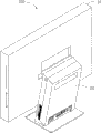
Fig. 1 is the solid assembling synoptic diagram of the integral computer of the embodiment of the invention, and this integral computer comprises supporting mechanism.
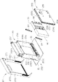
Fig. 2 is the sectional perspective decomposing schematic representation of supporting mechanism shown in Figure 1.
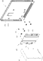
Fig. 3 is the further perspective exploded view of supporting mechanism shown in Figure 2, and this supporting mechanism comprises location-plate.
Fig. 4 is the perspective exploded view of location-plate shown in Figure 3 and hard disk.
Fig. 5 is similar to Fig. 2, demonstration be the supporting mechanism view in when dismounting.
The main element symbol description
Supporting mechanism 20
Gag lever post 24
Bonnet 29
Fixed orifice 31
Bending part 63
Pilot hole 65
Screw 70
Screw 252
First bending part 253
Articulated section 254
Main body 271,291
Flanging 273,293
First pivoted hole 2331
Second pivoted hole 2333
First clamping part 2373
Axis hole 2541
Through hole 2731
Grip part 2911
Embodiment
Below in conjunction with drawings and Examples to supporting mechanism of the present invention and use the integral computer of this supporting mechanism to be described in further detail.
See also Fig. 1, the integral computer 100 of the embodiment of the invention comprises display screen 10 and is used for the supporting mechanism 20 of supporting display screen 10.
See also Fig. 2, supporting mechanism 20 comprises pedestal 21, bracing frame 23, the activity on the pedestal 21 of being fixed at be located at bracing frame 23 away from the portable plate 25 of display screen 10 1 sides, be located at bracing frame 23 near the protecgulum 27 of display screen 10 1 sides and be located at the bonnet 29 of portable plate 25 away from display screen 10 1 sides.
See also Fig. 3, pedestal 21 is roughly square plate.Bracing frame 23 is for being located at the square box body structure on the pedestal 21, and it comprises the substrate 231 near display screen 10 1 sides, two side plates 233 that link to each other with substrate 231 left and right sides and the top board 235 that links to each other with substrate 231 tops.Substrate 231, two side plates 233, top board 235 and pedestals 21 are jointly around forming an accommodation space 236.Integral computer 100 also comprises mainboard (figure does not show), hard disk 30, power supply 40 and the external interface module 50 that is contained in the accommodation space 236.Wherein, hard disk 30 and power supply 40 are removable installed in portable plate 25 1 sides side by side, and external interface module 50 is provided with near pedestal 21.This mainboard is electrically connected with hard disk 30, power supply 40 and external interface module 50 respectively by some leads (figure does not show).Accommodation space 236 comprises an opening (not indicating), and hardware devices such as above-mentioned mainboard all enter in the accommodation space 236 by opening.Portable plate 25 1 ends are rotationally connected with two side plates 233 of bracing frame 23, to expose or to cover accommodation space 236.
Each side plate 233 offers first pivoted hole 2331 near the position of bottom, and the position at close middle part offers second pivoted hole 2333.Supporting mechanism 20 also comprises is located at the shell fragment 237 of each side plate 233 near apical position.Shell fragment 237 1 ends are fixed in side plate 233, and the other end forms the round button portion 2371 that keeps at a certain distance away with side plate 233 and first clamping part 2373 adjacent with button portion 2371.In the present embodiment, first clamping part 2373 is a grab.
Each first bending part, 253 bottom forms an articulated section 254.Offer the axis hole 2541 that matches with first pivoted hole 2331 of side plate 233 on the articulated section 254.Supporting mechanism 20 also comprises two screws 252.Each screw 252 passes axis hole 2541 and is locked on first pivoted hole 2331, thus portable plate is articulated in two side plates 233 rotationally by two articulated sections 254.Each first bending part, 253 middle part also offers strip chute 256.Supporting mechanism 20 also comprises two gag lever posts 24.Each gag lever post 24 1 end is articulated in second pivoted hole 2333 of side plate 233 by screw (figure do not show), and the other end is movably set in the chute 256 by screw (scheming not show).
Second bending part, 255 middle parts are formed with second holding section 2551 that first holding section 2351 with top board 235 fastens.In the present embodiment, second holding section 2551 is a connecting hole.
Please consult Fig. 2 once more, bonnet 29 is roughly the square casing that matches with protecgulum 27, and it comprises main body 291 and vertical two flangings 293 that extend to form to a side bending from two ends, main body 291 left and right sides.Main body 291 is formed with the grip part 2911 that caves inward near the position at top, so that use hand grip.Position near the top on each flanging 293 respectively forms second clamping part 2931 that matches with first clamping part 2373 that holds shell fragment 237.In the present embodiment, second clamping part 2931 is a grab.
See also Fig. 4, integral computer 100 also comprises the hard disk bracket 60 that is fixed in hard disk 30 1 sides, four screws 70 and four elastic washers 80.Offer four fixed orifices 31 on the hard disk 30.The shape of hard disk bracket 60 and hard disk 30 are roughly the same, and it comprises fixed head 61 and vertical respectively four bending parts 63 that extend to form from fixed head 61 both sides.Hard disk 30 can just be sticked between four bending parts 63.The position of corresponding four fixed orifices 31 also offers four pilot holes 65 respectively on the fixed head 61.Four elastic washers 80 are sticked in respectively in four pilot holes 65.Each screw 70 passes an elastic washer 80 and is screwed together in the fixed orifice 31, thus hard disk 30 is fixed on the hard disk bracket 60.Because elastic washer 80 has played certain bumper and absorbing shock effect at hard disk 30 and hard disk bracket 60, so the better working stability of hard disk 30.Also be provided with a plurality of buckling parts 2511 that match with the edge of fixed head 61 on the lid 251 of portable plate 25.In the present embodiment, buckling parts 2511 is the lug of a bending, and hard disk bracket 60 is installed between a plurality of buckling parts 2511 slidably.
Please consult Fig. 2 and Fig. 5 simultaneously, when needs will be such as the element the hard disk 30 when supporting mechanism 20 unloads, press the button portion 2371 that is positioned at protecgulum 27 both sides at first simultaneously, so that first clamping part 2373 separates with second clamping part 2931 of bonnet 29, can comparatively easily bonnet 29 be unloaded from bracing frame 23 thus.Press first holding section 2351 of lower roof plate 235 then, first holding section 2351 is broken away from from second holding section 2551 of portable plate 25,, portable plate 25 254 is rotated around the articulated section relative to bracing frame 23 again to second bending part, 255 application of forces of portable plate 25.In this process, gag lever post 24 1 ends rotate relative to bracing frame 23, and the other end slides in the chute 256 of portable plate 25.When the end of gag lever post 24 slides into when offseting with chute 256 1 ends, portable plate 25 can't be rotated further and rest on position with pedestal 21 almost parallels.Outside accommodation space 236 is exposed at this moment, can comparatively easily hard disk 30 (together with hard disk bracket 60) be extracted out from portable plate 25 thus.Be appreciated that this moment, other hardware devices such as mainboard, power supply 40 also can take out from accommodation space 236 comparatively easily.After hard disk 30 equipment replacements such as grade finish, again to second bending part, 255 application of forces of portable plate 25, make portable plate 25 around the articulated section 254 relative bracing frame 23 backward rotation and cover accommodation space 236.
Be appreciated that, first holding section 2351, second holding section 2551, first clamping part 2373, second clamping part, 2931 structure also are not limited to structures such as described grab of present embodiment or buckle, its shape and form the position and all can adjust according to different demands.Protecgulum 27, bonnet 29, shell fragment 237, external interface module 50 and hard disk bracket 60 also can omit.
In addition, those skilled in the art can also do other variation in spirit of the present invention, and certainly, these are included within the scope of protection of present invention according to the variation that spirit of the present invention is done.
Claims (10)
1. supporting mechanism, comprise pedestal and the bracing frame that is fixed on this pedestal, it is characterized in that: this bracing frame is the frame structure with an accommodation space, this supporting mechanism also comprises portable plate and gag lever post, this portable plate one end is rotationally connected with this bracing frame, also offer chute on this portable plate, this gag lever post one end is rotationally connected with this bracing frame, the other end is movably set in this chute, and this portable plate is by rotating relative to this bracing frame with in the position that exposes this accommodation space and cover between the position of this accommodation space and switch.
2. supporting mechanism as claimed in claim 1, it is characterized in that: this bracing frame comprises substrate and the two opposite side plates that link to each other with these substrate two ends, this portable plate comprises lid and 2 first bending parts that extend to form to the same side bending from these lid two ends, each first bending part comprises the articulated section that is positioned at an end, and this portable plate is articulated in this two side plate respectively by this two articulated section.
3. supporting mechanism as claimed in claim 2 is characterized in that: this gag lever post one end is articulated in wherein on the side plate, and this chute is opened on this first bending part.
4. supporting mechanism as claimed in claim 2, it is characterized in that: this bracing frame also comprises the top board that connects this two side plate, be formed with first holding section on this top board, this portable plate is formed with second holding section of matching with this first holding section away from an end of this two articulated section.
5. supporting mechanism as claimed in claim 1, it is characterized in that: this supporting mechanism also comprises the bonnet that is positioned at close this portable plate one side of this bracing frame, this bracing frame one side is provided with first clamping part, and this bonnet is provided with second clamping part that matches with this first clamping part.
6. supporting mechanism as claimed in claim 5, it is characterized in that: this supporting mechanism comprises the shell fragment of being located at this bracing frame one side, this shell fragment one end is formed with button portion, this first buckle part is on this shell fragment and adjacent with this button portion, this supporting mechanism also comprises and is positioned at this bracing frame away from this portable plate one side, and, offer the through hole that holds this button portion on this protecgulum with the protecgulum that this bonnet matches.
7. integral computer, comprise display screen, hard disk and support the supporting mechanism of this display screen, on this supporting mechanism comprises pedestal and is fixed at this pedestal and the bracing frame that links to each other with this display screen, it is characterized in that: this bracing frame is the frame structure with an accommodation space, this supporting mechanism also comprises portable plate and gag lever post, this hard disk removably is located on this portable plate and is positioned at this accommodation space, this portable plate one end is rotationally connected with this bracing frame, also offer chute on this portable plate, this gag lever post one end is rotationally connected with this bracing frame, the other end is movably set in this chute, and this portable plate is by rotating relative to this bracing frame with in the position that exposes this accommodation space and cover between the position of this accommodation space and switch.
8. integral computer as claimed in claim 7 is characterized in that: this integral computer also comprises the hard disk bracket that is fixed in this hard disk one side, is formed with a plurality of buckling parts that match with the edge of this hard disk bracket on this portable plate.
9. integral computer as claimed in claim 8, it is characterized in that: this hard disk one side offers fixed orifice, offer on this hard disk bracket and this fixed orifice corresponding positioning hole, this integral computer also comprises screw and is located at the interior elastic washer of this pilot hole that this screw passes this elastic washer and is screwed together in this fixed orifice.
10. integral computer as claimed in claim 7 is characterized in that: this integral computer also comprises to be located on this portable plate, and the power supply adjacent with this hard disk.
Priority Applications (2)
| Application Number | Priority Date | Filing Date | Title |
|---|---|---|---|
| CN201010123296.8A CN102193587B (en) | 2010-03-12 | 2010-03-12 | Support mechanism and integrated computer using the support mechanism |
| US12/776,515 US8144452B2 (en) | 2010-03-12 | 2010-05-10 | Supporting mechanism and all-in-one computer using the same |
Applications Claiming Priority (1)
| Application Number | Priority Date | Filing Date | Title |
|---|---|---|---|
| CN201010123296.8A CN102193587B (en) | 2010-03-12 | 2010-03-12 | Support mechanism and integrated computer using the support mechanism |
Publications (2)
| Publication Number | Publication Date |
|---|---|
| CN102193587A true CN102193587A (en) | 2011-09-21 |
| CN102193587B CN102193587B (en) | 2014-03-26 |
Family
ID=44559785
Family Applications (1)
| Application Number | Title | Priority Date | Filing Date |
|---|---|---|---|
| CN201010123296.8A Expired - Fee Related CN102193587B (en) | 2010-03-12 | 2010-03-12 | Support mechanism and integrated computer using the support mechanism |
Country Status (2)
| Country | Link |
|---|---|
| US (1) | US8144452B2 (en) |
| CN (1) | CN102193587B (en) |
Cited By (7)
| Publication number | Priority date | Publication date | Assignee | Title |
|---|---|---|---|---|
| CN103625516A (en) * | 2012-08-21 | 2014-03-12 | 成都弥荣科技发展有限公司 | Pushing platform for mobile automobile detection liquid crystal display |
| CN104102285A (en) * | 2013-04-09 | 2014-10-15 | 和硕联合科技股份有限公司 | Combination device capable of supporting display device and electronic device with combination device |
| CN104238629A (en) * | 2013-06-07 | 2014-12-24 | 鸿富锦精密工业(深圳)有限公司 | Integrated computer |
| CN105491313A (en) * | 2014-09-15 | 2016-04-13 | 鸿富锦精密工业(深圳)有限公司 | Display device and mechanism structure |
| CN105630101A (en) * | 2014-11-26 | 2016-06-01 | 鸿富锦精密工业(武汉)有限公司 | Electronic device shell and electronic device |
| CN109739304A (en) * | 2018-12-29 | 2019-05-10 | 联想(北京)有限公司 | Adapter assembly and electronic system, the integral computer of first electronic equipment |
| CN110554745A (en) * | 2019-07-11 | 2019-12-10 | 苏州浪潮智能科技有限公司 | Riser card mounting structure |
Families Citing this family (12)
| Publication number | Priority date | Publication date | Assignee | Title |
|---|---|---|---|---|
| TWI515528B (en) * | 2010-12-29 | 2016-01-01 | 鴻海精密工業股份有限公司 | All-in-one computer |
| CN102654234A (en) * | 2011-03-04 | 2012-09-05 | 鸿富锦精密工业(深圳)有限公司 | Electronic device |
| CN102695385A (en) * | 2011-03-25 | 2012-09-26 | 鸿富锦精密工业(深圳)有限公司 | Electronic device |
| TWM428643U (en) * | 2011-12-30 | 2012-05-01 | Pegatron Corp | Electronic apparatus |
| US10514729B2 (en) | 2014-11-12 | 2019-12-24 | Hewlett-Packard Development Company, L.P. | Support member for a computing device |
| US20170329364A1 (en) * | 2014-11-27 | 2017-11-16 | Lg Electronics Inc. | Display device |
| US9727096B1 (en) * | 2016-02-09 | 2017-08-08 | Lenovo (Singapore) Pte. Ltd. | All-in-one with sliding mechanism to reveal removable modules |
| CN106292873A (en) * | 2016-08-01 | 2017-01-04 | 联想(北京)有限公司 | A kind of computer all-in-one machine |
| CN108733138A (en) * | 2017-04-21 | 2018-11-02 | 鸿富锦精密工业(武汉)有限公司 | Integral computer |
| US10452096B1 (en) * | 2018-06-15 | 2019-10-22 | Dell Products L.P. | Configurable all-in-one modular desktop computing system |
| US11477902B2 (en) * | 2020-06-30 | 2022-10-18 | Dell Products L.P. | Cartridge-based computing system |
| CN112783292B (en) * | 2021-01-29 | 2022-09-13 | 兰州大学 | Computer hard disk shock attenuation protection device |
Citations (2)
| Publication number | Priority date | Publication date | Assignee | Title |
|---|---|---|---|---|
| CN201044069Y (en) * | 2007-01-23 | 2008-04-02 | 谢坤祥 | Data access unit locating structure |
| CN201387569Y (en) * | 2009-04-24 | 2010-01-20 | 天津市隆君电子科技有限公司 | Small-sized touch PC all-in-one machine |
Family Cites Families (9)
| Publication number | Priority date | Publication date | Assignee | Title |
|---|---|---|---|---|
| TW457445B (en) * | 2000-02-24 | 2001-10-01 | Acer Inc | Flat display capable of replacing different bases |
| US6680843B2 (en) * | 2001-09-28 | 2004-01-20 | International Business Machines Corporation | All-in-one personal computer with tool-less quick-release features for various elements thereof including a reusable thin film transistor monitor |
| USD504426S1 (en) * | 2004-06-08 | 2005-04-26 | Flextronics International Usa, Inc. | Desktop computer |
| US7770856B2 (en) * | 2004-08-13 | 2010-08-10 | Hewlett-Packard Development Company, L.P. | Thin computer monitor support apparatus |
| US7555581B2 (en) * | 2005-10-17 | 2009-06-30 | Hewlett-Packard Development Company, L.P. | Communications display base system and method |
| CN101481073B (en) * | 2008-01-09 | 2012-03-14 | 鸿富锦精密工业(深圳)有限公司 | Lifting mechanism and cylinder thereof |
| CN101493179B (en) * | 2008-01-22 | 2011-07-27 | 鸿富锦精密工业(深圳)有限公司 | Lifting mechanism |
| CN101989103B (en) * | 2009-07-29 | 2012-10-10 | 鸿富锦精密工业(深圳)有限公司 | Computer all-in-one machine |
| CN102033575A (en) * | 2009-09-24 | 2011-04-27 | 鸿富锦精密工业(深圳)有限公司 | Electronic device |
-
2010
- 2010-03-12 CN CN201010123296.8A patent/CN102193587B/en not_active Expired - Fee Related
- 2010-05-10 US US12/776,515 patent/US8144452B2/en not_active Expired - Fee Related
Patent Citations (2)
| Publication number | Priority date | Publication date | Assignee | Title |
|---|---|---|---|---|
| CN201044069Y (en) * | 2007-01-23 | 2008-04-02 | 谢坤祥 | Data access unit locating structure |
| CN201387569Y (en) * | 2009-04-24 | 2010-01-20 | 天津市隆君电子科技有限公司 | Small-sized touch PC all-in-one machine |
Cited By (9)
| Publication number | Priority date | Publication date | Assignee | Title |
|---|---|---|---|---|
| CN103625516A (en) * | 2012-08-21 | 2014-03-12 | 成都弥荣科技发展有限公司 | Pushing platform for mobile automobile detection liquid crystal display |
| CN104102285A (en) * | 2013-04-09 | 2014-10-15 | 和硕联合科技股份有限公司 | Combination device capable of supporting display device and electronic device with combination device |
| CN104102285B (en) * | 2013-04-09 | 2017-06-16 | 和硕联合科技股份有限公司 | Combination device capable of supporting display device and electronic device with combination device |
| CN104238629A (en) * | 2013-06-07 | 2014-12-24 | 鸿富锦精密工业(深圳)有限公司 | Integrated computer |
| CN105491313A (en) * | 2014-09-15 | 2016-04-13 | 鸿富锦精密工业(深圳)有限公司 | Display device and mechanism structure |
| CN105630101A (en) * | 2014-11-26 | 2016-06-01 | 鸿富锦精密工业(武汉)有限公司 | Electronic device shell and electronic device |
| CN109739304A (en) * | 2018-12-29 | 2019-05-10 | 联想(北京)有限公司 | Adapter assembly and electronic system, the integral computer of first electronic equipment |
| CN109739304B (en) * | 2018-12-29 | 2020-12-18 | 联想(北京)有限公司 | Adaptation assembly of first electronic equipment, electronic system and integrated computer |
| CN110554745A (en) * | 2019-07-11 | 2019-12-10 | 苏州浪潮智能科技有限公司 | Riser card mounting structure |
Also Published As
| Publication number | Publication date |
|---|---|
| US20110222231A1 (en) | 2011-09-15 |
| CN102193587B (en) | 2014-03-26 |
| US8144452B2 (en) | 2012-03-27 |
Similar Documents
| Publication | Publication Date | Title |
|---|---|---|
| CN102193587B (en) | Support mechanism and integrated computer using the support mechanism | |
| EP3220229B1 (en) | Hinge assembly for electronic device | |
| US6697250B2 (en) | Liquid crystal display computer with a removable device frame | |
| US8023258B2 (en) | Computer enclosure and storage device module thereof | |
| US20060133020A1 (en) | Common pivot arrangement of portable computer | |
| US8134843B2 (en) | Server | |
| CN101571735A (en) | Electronic device | |
| US20060164802A1 (en) | Portable computer enclosure | |
| US20080158809A1 (en) | Computer enclosure incorporating drive bracket | |
| US7164577B2 (en) | Electronic apparatus having storage device | |
| US20120217856A1 (en) | Electronic device enclosure for receiving storage device | |
| US8596472B2 (en) | Electronic device enclosure | |
| US9250662B2 (en) | Holding frame and housing assembly for electronic device | |
| CN102200805A (en) | Hard disc fixing mechanism and electronic device with same | |
| US20130026896A1 (en) | Assembly structure for assembling panel modules with different sizes and panel device therewith | |
| CN202995593U (en) | Latch and shell fixing device | |
| CN105867559A (en) | All-in-one personal computer back device with independent separation function | |
| CN202339522U (en) | Ultrathin chassis capable of being installed with display | |
| CN203164823U (en) | Safe plastic housing chassis portable computer | |
| CN201668386U (en) | Portable electrocardiograph capable of being easily regulate display angle | |
| CN201138458Y (en) | Positioning apparatus of computer main board tray | |
| CN207718327U (en) | A kind of portable notebook external connection keyboard | |
| US20040252450A1 (en) | Computer mainframe | |
| CN109240448A (en) | A kind of novel computer mainframe box | |
| CN219225416U (en) | Quick detach structure and desk-top machine case of quick-witted case power |
Legal Events
| Date | Code | Title | Description |
|---|---|---|---|
| C06 | Publication | ||
| PB01 | Publication | ||
| C10 | Entry into substantive examination | ||
| SE01 | Entry into force of request for substantive examination | ||
| GR01 | Patent grant | ||
| GR01 | Patent grant | ||
| CF01 | Termination of patent right due to non-payment of annual fee |
Granted publication date: 20140326 Termination date: 20150312 |
|
| EXPY | Termination of patent right or utility model |