CN102184546B - Image processing apparatus, image processing method and image processing program - Google Patents
Image processing apparatus, image processing method and image processing program Download PDFInfo
- Publication number
- CN102184546B CN102184546B CN201110004273.XA CN201110004273A CN102184546B CN 102184546 B CN102184546 B CN 102184546B CN 201110004273 A CN201110004273 A CN 201110004273A CN 102184546 B CN102184546 B CN 102184546B
- Authority
- CN
- China
- Prior art keywords
- representative point
- pixel
- evaluation function
- correlativity
- value
- Prior art date
- Legal status (The legal status is an assumption and is not a legal conclusion. Google has not performed a legal analysis and makes no representation as to the accuracy of the status listed.)
- Expired - Fee Related
Links
Images


Classifications
-
- G—PHYSICS
- G06—COMPUTING; CALCULATING OR COUNTING
- G06T—IMAGE DATA PROCESSING OR GENERATION, IN GENERAL
- G06T7/00—Image analysis
- G06T7/20—Analysis of motion
- G06T7/223—Analysis of motion using block-matching
- G06T7/238—Analysis of motion using block-matching using non-full search, e.g. three-step search
-
- G—PHYSICS
- G06—COMPUTING; CALCULATING OR COUNTING
- G06T—IMAGE DATA PROCESSING OR GENERATION, IN GENERAL
- G06T7/00—Image analysis
- G06T7/20—Analysis of motion
- G06T7/207—Analysis of motion for motion estimation over a hierarchy of resolutions
-
- H—ELECTRICITY
- H04—ELECTRIC COMMUNICATION TECHNIQUE
- H04N—PICTORIAL COMMUNICATION, e.g. TELEVISION
- H04N19/00—Methods or arrangements for coding, decoding, compressing or decompressing digital video signals
- H04N19/10—Methods or arrangements for coding, decoding, compressing or decompressing digital video signals using adaptive coding
- H04N19/169—Methods or arrangements for coding, decoding, compressing or decompressing digital video signals using adaptive coding characterised by the coding unit, i.e. the structural portion or semantic portion of the video signal being the object or the subject of the adaptive coding
- H04N19/17—Methods or arrangements for coding, decoding, compressing or decompressing digital video signals using adaptive coding characterised by the coding unit, i.e. the structural portion or semantic portion of the video signal being the object or the subject of the adaptive coding the unit being an image region, e.g. an object
- H04N19/176—Methods or arrangements for coding, decoding, compressing or decompressing digital video signals using adaptive coding characterised by the coding unit, i.e. the structural portion or semantic portion of the video signal being the object or the subject of the adaptive coding the unit being an image region, e.g. an object the region being a block, e.g. a macroblock
-
- H—ELECTRICITY
- H04—ELECTRIC COMMUNICATION TECHNIQUE
- H04N—PICTORIAL COMMUNICATION, e.g. TELEVISION
- H04N19/00—Methods or arrangements for coding, decoding, compressing or decompressing digital video signals
- H04N19/50—Methods or arrangements for coding, decoding, compressing or decompressing digital video signals using predictive coding
- H04N19/503—Methods or arrangements for coding, decoding, compressing or decompressing digital video signals using predictive coding involving temporal prediction
- H04N19/51—Motion estimation or motion compensation
- H04N19/533—Motion estimation using multistep search, e.g. 2D-log search or one-at-a-time search [OTS]
-
- H—ELECTRICITY
- H04—ELECTRIC COMMUNICATION TECHNIQUE
- H04N—PICTORIAL COMMUNICATION, e.g. TELEVISION
- H04N19/00—Methods or arrangements for coding, decoding, compressing or decompressing digital video signals
- H04N19/50—Methods or arrangements for coding, decoding, compressing or decompressing digital video signals using predictive coding
- H04N19/503—Methods or arrangements for coding, decoding, compressing or decompressing digital video signals using predictive coding involving temporal prediction
- H04N19/51—Motion estimation or motion compensation
- H04N19/537—Motion estimation other than block-based
-
- H—ELECTRICITY
- H04—ELECTRIC COMMUNICATION TECHNIQUE
- H04N—PICTORIAL COMMUNICATION, e.g. TELEVISION
- H04N19/00—Methods or arrangements for coding, decoding, compressing or decompressing digital video signals
- H04N19/60—Methods or arrangements for coding, decoding, compressing or decompressing digital video signals using transform coding
- H04N19/61—Methods or arrangements for coding, decoding, compressing or decompressing digital video signals using transform coding in combination with predictive coding
-
- G—PHYSICS
- G06—COMPUTING; CALCULATING OR COUNTING
- G06T—IMAGE DATA PROCESSING OR GENERATION, IN GENERAL
- G06T2207/00—Indexing scheme for image analysis or image enhancement
- G06T2207/20—Special algorithmic details
- G06T2207/20021—Dividing image into blocks, subimages or windows
-
- H—ELECTRICITY
- H04—ELECTRIC COMMUNICATION TECHNIQUE
- H04N—PICTORIAL COMMUNICATION, e.g. TELEVISION
- H04N19/00—Methods or arrangements for coding, decoding, compressing or decompressing digital video signals
- H04N19/50—Methods or arrangements for coding, decoding, compressing or decompressing digital video signals using predictive coding
- H04N19/503—Methods or arrangements for coding, decoding, compressing or decompressing digital video signals using predictive coding involving temporal prediction
- H04N19/51—Motion estimation or motion compensation
- H04N19/577—Motion compensation with bidirectional frame interpolation, i.e. using B-pictures
Landscapes
- Engineering & Computer Science (AREA)
- Multimedia (AREA)
- Signal Processing (AREA)
- Computer Vision & Pattern Recognition (AREA)
- Physics & Mathematics (AREA)
- General Physics & Mathematics (AREA)
- Theoretical Computer Science (AREA)
- Image Analysis (AREA)
- Compression Or Coding Systems Of Tv Signals (AREA)
Abstract
The invention discloses an image processing apparatus, an image processing method and an image processing program. The image processing apparatus includes a representative-point storing section; an evaluation-value table generation section; a peak detection section; and a correlation determination section, wherein an operation carried out by the evaluation-value table generation section to generate the evaluation-value table on the basis of representative points stored in the representative-point storing section, an operation carried out by the peak detection section to detect the candidate vector, an operation carried out by the correlation determination section to determine the correlation between the representative point and the referenced point as well as an operation carried out by the correlation determination section to update the representative-point storing section in accordance with a result of the operation to determine a correlation between the representative point and the referenced point are repeated as long as existence of a significant candidate vector is determined.
Description
Technical field
The present invention relates to image processing equipment, image processing method and image processing program.More specifically, the present invention relates to improve the image processing equipment for detection of the precision of the operation of motion vector by its execution by improving the precision of the candidate vector that will extract, the image processing method that will be adopted by this equipment, and the image processing program of realizing the method.
Background technology
The recent progress of processing along with the signal that moving images is carried out, is applied to various fields for detection of the technology of the motion vector of each object on image.For example, for detection of the technology of the motion vector of each object on image be used in the frame rate conversion of the motion compensation type coding implemented as high-performance code, moving images, in traffic monitoring system for detection of among the processing of mobile object, mobile Check processing etc.For detect detection that the technology of parallax (disparity) vector is applied to the image from utilizing stereoscopic camera to take, mobile object being carried out, depth survey etc. from appearing at the image of a plurality of points.To the detection of the motion vector of moving images to appearing at the difference each other of detection of disparity vector of each image of a plurality of points, be only that these detections just have for setting up the different relations between associated image.From the viewpoint of technology, to the detection of the motion vector of moving images with identical to appearing at the detection of disparity vector of each image of a plurality of points.Because this reason, to the detection of the motion vector of moving images with to appearing at the detection of disparity vector of each image of a plurality of points, be called as vector detection.
In the past, in vector detection, extensively adopted frame matching technique.According to frame matching technique, carry out full search operation with all pieces of datas in comparison search region.Therefore, frame matching technique has following shortcoming: the number of times of the comparison of carrying out in all pieces of datas in comparison search region is very large, and time execute vector that therefore need to be longer detects.
In addition, if frame has comprised a plurality of parts with different moving directions, utilize the movement be used as this frame of unit and detect to represent the indivedual movements in this frame, the movement that the above-mentioned movement detecting can not say pin-point accuracy and detects.The size that such problem can arrange by the value suitably to adjust frame solves.If the size of frame is arranged on excessive value, calculated amount increases.In addition,, in the situation that the size of frame is arranged on excessive value, easily there is the problem that a plurality of movements in frame cause.If being arranged on too small value, the size of frame comprises a plurality of movements to prevent frame, for determining the size reduction in the region of matching status.Therefore, in the case, there is the problem of the precision deterioration of mobile detection.
In order to address the above problem, the present inventor has proposed a kind of motion vector detecting apparatus, this motion vector detecting apparatus can detect the motion vector of each pixel and not increase calculated amount, and can avoid incorrect motion vector to detect, in addition, the present inventor has also proposed the motion vector detecting method being adopted by the motion vector pick-up unit described in Japanese Patent Laid Open Publication 2005-175869 (as patent documentation 1) and 2005-175870 (as patent documentation 2).
According to the some point as motion vector detecting method, described in patent documentation 1 and 2, be that each pixel or each pixel frame calculate evaluation of estimate.Yet in the case, motion vector is not directly to determine.On the contrary, by adopting candidate vector method to solve the problem occurring in the past.According to candidate vector method, first, as first step, by adopting representative point matching technique, be that image generates evaluation of estimate table, and extract some candidate vector from generated evaluation of estimate table.Then, as second step, for each pixel, from candidate vector, select to be considered to best candidate vector.Selected candidate vector is used as motion vector.In this way, can be each pixel and determine motion vector.
According to candidate vector method, the only active position in extraction region of search, first step place (that is to say the position of candidate vector), to reduce calculated amount.Likely, on the border of the image of reference object, cursorily carried out incorrect vector detection.Such border of the same image for reference object, optimal vector is definite from minority candidate vector, and after the number of candidate vector has been reduced, above-mentioned minority candidate vector is determined in advance.With this, to compare with the operation of the whole region of search of search, the possibility that different pixels is produced to identical evaluation of estimate is lower, and the possibility of incorrect vector detection is also lowered.
Summary of the invention
Yet, according to disclosed motion vector detecting method in patent documentation 1 and 2, for extract the operation of candidate vector from each evaluation of estimate table, be necessary to set in advance the number of the candidate vector that will extract from evaluation of estimate table.As a result, there is problem below.
If the number of the candidate vector of extracting from evaluation of estimate table is set to the value larger than the number of the significant candidate vector existing image, the candidate vector extracted comprises that the possibility of unnecessary candidate vector is higher.Therefore,, in the processing of carrying out for the vectorial second step place of selecting to be considered to best, the possibility of incorrect vector detection increases.On the contrary, on the other hand, if the number of the candidate vector of extracting from evaluation of estimate table is set to less value to reduce the possibility of incorrect vector detection, the candidate vector extracted does not comprise that the possibility of necessary candidate vector is higher.Equally in the case, likely, in the processing of carrying out for the vectorial second step place of selecting to be considered to best, the possibility of incorrect vector detection also increases.
That is to say, in order to determine optimal motion vectors, as condition precedent, the precision of the candidate vector of extracting at first step place must be high.Depend on the value that the number of the candidate vector that will extract from evaluation of estimate table is set to, the candidate vector of extracting may comprise unnecessary candidate vector, or the candidate vector of extracting may not comprise necessary candidate vector.That is to say, depend on the value that the number of the candidate vector that will extract from evaluation of estimate table is set to, the precision of candidate vector in some cases may be poor.
In the situation that managing to address the above problem, the present inventor has passed through to improve the precision of the candidate vector of extracting according to candidate vector method, and has improved the precision of the detection of motion vector.
A kind of according to an embodiment of the invention image processing equipment has been used: representative point memory storage, this representative point memory storage plays for storing the effect of the memory storage of a plurality of pixels, wherein each pixel in a plurality of pixels is present on benchmark image as representative point, for representative point, be for detecting motion vector by benchmark image and reference picture being made comparisons detect the operation of the motion vector of the representative point that represents the pixel on benchmark image; And evaluation of estimate table creating device, this evaluation of estimate table creating device is for generating evaluation of estimate table by employing representative point matching technique, and this representative point matching technique has been used the representative point of storing in representative point memory storage.Image processing equipment has also been used: peak detector, this peak detector for by the evaluation of estimate of storing with evaluation of estimate table and the corresponding position probing of maximal value be candidate vector, this candidate vector is as the candidate of motion vector; And correlativity determining device, this correlativity determining device is determined representative point on benchmark image and the correlativity being used as between the point of ending place reference point, that be present in the candidate vector detecting for representative point on reference picture for each in a plurality of aforementioned representative point of storing for representative point memory storage, and this correlativity determining device is for deleting the representative point with high correlation, to upgrade representative point memory storage from representative point memory storage.In image processing equipment, as long as determined the existence of significant candidate vector, just repeatedly carry out following operation: by evaluation of estimate table creating device, carried out, for the representative point of storing based on representative point memory storage, generate the operation of evaluation of estimate table, by peak detector, carried out, operation for detection of candidate vector, by correlativity determining device, carried out, for determining the operation of the correlativity between representative point and reference point, and carried out by correlativity determining device, for upgrade the operation of representative point memory storage according to the result of the operation of the correlativity between definite representative point and reference point.
Image processing method is for driving a method for image processing equipment according to an embodiment of the invention, and this image processing equipment is used for carrying out predetermined image to be processed.As long as image processing method has comprised the steps: to determine the existence of significant candidate vector, just repeatedly drive image processing equipment, to repeatedly carry out following processing: by adopting representative point matching technique to generate the processing of evaluation of estimate table, wherein representative point matching technique for representative point memory storage is stored, each is present on benchmark image as each in a plurality of pixels of representative point, make comparisons with reference picture; By the evaluation of estimate with storing in evaluation of estimate table and the processing that is candidate vector of the corresponding position probing of maximal value, wherein candidate vector is as the candidate of the motion vector between benchmark image and reference picture; And determine representative point on benchmark image and as the correlativity between the point of ending place reference point, that be present in the candidate vector detecting for representative point on reference picture for each in a plurality of aforementioned representative point of storing in representative point memory storage, and from representative point memory storage, delete and there is the representative point of high correlation to upgrade the processing of representative point memory storage.
A kind of according to an embodiment of the invention image processing program is the program that will be moved by computing machine, this computing machine is used for carrying out processing, this processing comprises the following steps: as long as determined the existence of significant candidate vector, just repeatedly move this step, to repeatedly carry out following processing: by adopting representative point matching technique to generate the processing of evaluation of estimate table, wherein representative point matching technique for representative point memory storage is stored, each is present on benchmark image as each in a plurality of pixels of representative point, make comparisons with reference picture; By the evaluation of estimate with storing in evaluation of estimate table and the processing that is candidate vector of the corresponding position probing of maximal value, wherein candidate vector is as the candidate of the motion vector between benchmark image and reference picture; And determine representative point on benchmark image and as the correlativity between the point of ending place reference point, that be present in the candidate vector detecting for representative point for each in a plurality of aforementioned representative point of storing in representative point memory storage, and the representative point that deletion has high correlation from representative point memory storage is to upgrade the processing of representative point memory storage, and wherein the pixel at reference point place is positioned on reference picture.
In an embodiment of the present invention, as long as determined the existence of significant candidate vector, just repeatedly carry out processing below.By adopting representative point matching technique to generate evaluation of estimate table, wherein representative point matching technique is made comparisons for each and the reference picture that each are stored in a plurality of pixels of the representative point of representative point memory storage on benchmark image.Then, by the evaluation of estimate with storing in evaluation of estimate table and the corresponding position probing of maximal value be candidate vector, wherein candidate vector is as the candidate of the motion vector between benchmark image and reference picture.Subsequently, for each, be stored in representative point memory storage as each in the representative point of the representative point on benchmark image, determine representative point with as reference point, and the point of ending place of the corresponding candidate vector of representative point between correlativity, wherein the pixel at reference point place is positioned on reference picture.Finally, from representative point memory storage, delete the representative point with high correlation, to upgrade representative point memory storage.
Be noted that can by through transmission medium, from program supplier to image processing equipment, download or by from the recording medium for pre-recorded program by installation at image processing equipment, and provide above-mentioned image processing program to user.
Image processing equipment can be the home block that autonomous device or equipment comprise.
According in the image processing equipment of various aspects of the present invention, image processing method and image processing program, improved the precision of the candidate vector that will extract, to increase the precision for detection of the operation of motion vector.
Accompanying drawing explanation
Fig. 1 is the block diagram that a general configuration that has realized the embodiment that applies image processing equipment of the present invention is shown;
Fig. 2 illustrates for the illustrative flow of the whole processing of being carried out by image processing equipment is described;
Fig. 3 is performed for generating the explanatory of the processing of evaluation of estimate table by representative point matching technique with to the calculating of vector (u, v);
Fig. 4 A and Fig. 4 B are performed for generating the explanatory of the processing of evaluation of estimate table by representative point matching technique with to the calculating of vector (u, v);
Fig. 5 is near the explanatory of the pixel of Existential Space gradient for detection of whether;
Fig. 6 is the block diagram of details that a general configuration of prototype selection parts is shown;
Fig. 7 is the block diagram that the image processing equipment of a detailed general configuration that has comprised candidate vector extraction parts is shown;
Fig. 8 illustrates and is performed for extracting the illustrative flow of the processing of candidate vector;
Fig. 9 is the block diagram of details that a general configuration of correlativity determining means is shown;
Figure 10 is the diagram that the type of waveform patterns is shown;
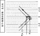
Figure 11 A and Figure 11 B are the explanatory that the correlativity of the situation with cumulative to the right shape of the type for waveform patterns is determined the details of processing;
Figure 12 A and Figure 12 B are the explanatory that correlativity that the type for waveform patterns has to the right a situation of shape is decrescence determined the details of processing;
Figure 13 A and Figure 13 B are that the type for waveform patterns has explanatory from the details of processing to the correlativity of the situation of the shape of lower convexity that determine;
Figure 14 A and Figure 14 B are the explanatory that the correlativity of the situation with the shape raising up of the type for waveform patterns is determined the details of processing;
Figure 15 illustrates and has summed up the table of horizontal direction evaluation function F1 to the equation of F4;
Figure 16 illustrates correlativity and determines the illustrative flow of processing;
Figure 17 is the conceptual diagram that candidate vector distributes (assignment) to process;
Figure 18 illustrates the illustrative flow of candidate vector allocation process; And
Figure 19 is the block diagram that a general configuration of the embodiment that has realized the computing machine that plays the effect of applying image processing equipment of the present invention is shown.
Embodiment
[block diagram of image processing equipment is shown]
Fig. 1 is the block diagram that a general configuration that has realized the x embodiment that applies image processing equipment 1 of the present invention is shown.
As shown in Figure 1, image processing equipment 1 is configured to comprise prototype selection parts 11, candidate vector extraction parts 12, control assembly 13 and candidate vector distribution member 14.
In the following description, input image data is used to refer to the data for incoming frame image.Yet, be noted that implementation of the present invention is never limited to the embodiment that input image data is the data of incoming frame image.For example, implementation of the present invention can also be that input image data is the embodiment of the data of input field image.In addition, the present invention also can be applicable to following situation: input image data is view data based on TV signal or the view data of the signal based on except TV signal.That is to say, input image data can be any in the view data of the various kinds such as interlaced data (interlaced data) or non-interlaced data.
As mentioned above, in this embodiment, each pixel comprising for reference frame, it is not the Pixel Information " 0 " of representative point that prototype selection parts 11 generate Pixel Information " 1 " or the indication pixel that indication pixel is representative point.Yet, be noted that prototype selection parts 11 also can arrange the number of the pixel that will extract from reference frame, and only the pixel of extracting from reference frame generated to such Pixel Information.
According to the control of being carried out by control assembly 13, for each representative point, candidate vector is extracted parts 12 and is extracted candidate vector, wherein each candidate vector is used as the candidate of motion vector representative point, that will be exported by image processing equipment 1, and candidate vector is extracted parts 12 to control assembly 13 supply candidate vector.Specifically, candidate vector is extracted parts 12 according to predetermined selecting sequence, and selects representative point from one or more representative points of having been determined by prototype selection parts 11.Then, candidate vector extraction parts 12 find the motion vector (u, v) of selected representative point to be used as candidate vector.Subsequently, candidate vector extraction parts 12 are repeatedly carried out and are supplied to control assembly 13 as the processing of candidate vector found motion vector (u, v), until control assembly 13 request candidate vector are extracted parts 12, stop processing.Note, in the following description, for by the motion vector (u that is extracted parts 12 by candidate vector and find, v) distinguish with the motion vector of being exported by image processing equipment 1, by candidate vector, extract the motion vector (u that parts 12 find, v) be referred to simply as vector (u, v), it is only the candidate of the motion vector exported by image processing equipment 1.
Intended pixel on candidate vector distribution member 14 benchmark images is set to observe pixel, and this observation pixel is as the object of processing and observed pixel.Candidate vector distribution member 14 is from selecting suitable candidate vector for observing pixel a plurality of candidate vector, and selected candidate vector determined to the motion vector of observing pixel for distributing to.Then, 14 outputs of candidate vector distribution member are distributed to and are observed the motion vector of pixel as the output movement vector of image processing equipment 1.
Candidate vector distribution member 14 can determine that any any pixel on benchmark image is used as observation pixel.For example, each pixel on candidate vector distribution member 14 benchmark images is set to observe pixel, and determines motion vector for each pixel on benchmark image.As an alternative, reference frame is divided into a plurality of frames, and the only pixel in each frame is used as observation pixel.In the situation that the only pixel in each frame is used as, observe pixel, by the determined motion vector of pixel for being used as the observation pixel of frame, represent the motion vector of all pixels in frame.
[flow process of the whole processing of being carried out by image processing equipment]
Fig. 2 illustrates the illustrative flow of the description of the performed whole processing of image processing equipment 1.
Subsequently, at next step S2 place, candidate vector is extracted the candidate vector of each in one or more representative points of prototype selection parts 11 decisions of parts 12 extractions, and the candidate vector of extracting to control assembly 13 supplies.When control assembly 13 extracts parts 12 to candidate vector, send instruction when stopping the processing to control assembly 13 supply candidate vector, candidate vector is extracted parts 12 and is stopped to the processing of control assembly 13 supply candidate vector.Therefore, candidate vector is extracted parts 12 and not necessarily to control assembly 13, is provided the candidate vector of extracting for each representative point being determined by prototype selection parts 11.
Then, at next step S3 place, candidate vector candidate vector, that from control assembly 13 receive of candidate vector distribution member 14 based on as extracted parts 12 extractions by candidate vector for the pixel on reference frame, decide the motion vector of each representative point that represents this pixel, and candidate vector distribution member 14 output movement vectors are as the output of image processing equipment 1.Specifically, for each pixel on reference frame, candidate vector distribution member 14 determines the candidate vector suitable for this pixel from a plurality of candidate vector of extracting parts 12 extractions by candidate vector for this pixel, and the motion vector using determined candidate vector as this pixel.Candidate vector distribution member 14 is the motion vector of each pixel on output reference frame then, as the output of image processing equipment 1.
As mentioned above, image processing equipment 1 is for each the pixel detection motion vector on the reference frame from input reference frame and input reference frame, and output movement vector is as vector data.
[explanation to representative point matching technique]
The processing of image processing equipment 1 is by improving the processing that in the patent documentation 1 and 2 of quoting in " background technology " chapters and sections, the disclosed candidate vector method being proposed is carried out.First description below illustrates the part that image processing equipment 1 comprises, this part is with acting on the part of carrying out the processing identical with processing based on the disclosed candidate vector method being proposed in patent documentation 1 and 2.The candidate vector method being proposed is one of candidate vector method of adopting of image processing equipment 1.
By reference to Fig. 3 and Fig. 4 A-4B, description has below illustrated and has been performed with by adopting representative point matching technique to generate the processing of evaluation of estimate table and being performed to find the calculating as the candidate's of motion vector vector (u, v).
According to representative point matching technique, first, the region of search corresponding with representative point on reference frame is arranged on reference frame.The region of search corresponding with representative point on reference frame have with reference frame on the center of position consistency of pixel.Pixel on reference frame is corresponding with the representative point on reference frame.Conventionally, the region of search being associated with representative point on reference frame has the yardstick of p pixel * q pixel, wherein p and q each be to be greater than 0 integer (p, q > 0).
In the generic instance shown in Fig. 3, the region of search Sa on reference frame is associated with the representative point Ra on reference frame, and region of search Sb on reference frame is associated with the representative point Rb on reference frame.
In order to make explanation easy to understand below, in the generic instance shown in Fig. 3, the position consistency of the center pixel of each in representative point Ra and Rb and impartial frame (uniform block), wherein impartial frame obtains as the result that reference frame is divided into such frame, and each frame has the horizontal scale of m pixel and the vertical dimension of n pixel equably.Yet, being noted that in reality, representative point is not necessarily distributed equably and is spreaded all over the surface of reference frame in this way.
Next, for each representative point, image processing equipment 1 is determined the correlativity between representative point and each pixel in the region of search arranging on reference frame as the region of search that is associated with representative point, to evaluation of estimate is set for each pixel in region of search.Specifically, if the pixel value of the pixel in region of search approaches the pixel value of representative point, or more specifically, if the difference between the pixel value of the pixel in region of search and the pixel value of representative point is not more than predetermined threshold value, the evaluation of estimate of the pixel in region of search is set to " 1 ".On the other hand, if the pixel value of the pixel in region of search is kept off the pixel value of representative point, or more specifically, if the difference between the pixel value of the pixel in region of search and the pixel value of representative point is greater than predetermined threshold value, the evaluation of estimate of the pixel in region of search is set to " 0 ".As a result, for representative point, the region of search being associated with representative point comprises that pixel that each has evaluation of estimate " 1 " and each have the pixel of evaluation of estimate " 0 ".
The position of the interested pixel in the interested region of search on interested reference frame is corresponding with the position of pixel included in the region of search being adjacent on another reference frame of interested reference frame, wherein a rear pixel is that each region of search has the yardstick of p pixel * q pixel as the pixel of the pixel corresponding with the interested pixel shown in Fig. 4 A of the region of search on continuous reference frame is shown.In the following description, the position of the interested pixel in the interested region of search on interested reference frame, and be called as relevant position as the position pixel corresponding with interested pixel, that each is included in a plurality of pixels in the region of search on another reference frame that is adjacent to interested reference frame.For interested pixel and the evaluation of estimate " 1 " finding in each pixel corresponding with interested pixel of corresponding position or " 0 " added and producing for the evaluation of estimate of interested pixel and.Evaluation of estimate and be therefore the summation of evaluation of estimate.Such evaluation of estimate and finding for each pixel in interested region of search, to be interested region of search generation evaluation of estimate table.Evaluation of estimate table be evaluation of estimate and table, each evaluation of estimate and finding for that forms in the pixel of region of search.Therefore, as shown in Figure 4 B, evaluation of estimate table has the yardstick identical with region of search.
In evaluation of estimate table, the correlativity of the pixel of the position in region of search is higher, the evaluation of estimate that this pixel of locating for this position (meaning above-mentioned relevant position) is calculated and just larger.The high correlation of the pixel of the position in region of search means that the pixel value of this pixel of this position and the pixel value at the representative point place that is associated with region of search mate well.Evaluation of estimate and the number that is also referred to as obtained evaluation of estimate " 1 ".Here, making the coordinate of the center of region of search is (0,0).In the case, have maximum evaluation of estimate and the coordinate of position be (u, v), this is the coordinate with respect to the center position coordinates as reference coordinate (0,0).In the following description, maximum evaluation of estimate and be also referred to as evaluation of estimate and maximal value.Each the label u and the v that in coordinate (u, v), use have indicated the coordinate figure as integer.As described after a while, for region of search, candidate vector is extracted parts 12 using relative position coordinates (u, v) as candidate vector (u, v).If representative point is associated with a plurality of regions of search, for evaluations of estimate among all regions of search that are associated with representative point, that there is increase and maximum peaked each region of search, candidate vector is extracted parts 12 and is all adopted relative position coordinates (u, v).
[detailed configurations of prototype selection parts]
Next, the details of prototype selection parts 11 is described below.
As described a little earlier, candidate vector is extracted the vector (u, v) that parts 12 are based upon evaluation of estimate included in the evaluation of estimate table of region of search generation and decide region of search, and the vector (u, v) that determined the most at last is as candidate vector.Therefore,, by improving the precision of evaluation of estimate table, can increase the precision of the processing of extracting candidate vector.
Because two reasons that the following describes, prototype selection parts 11 select following specific pixel as representative point: this specific pixel has the pixel value of the pixel value that is different from the pixel contiguous with this specific pixel.First, according to representative point matching technique, image processing equipment 1 evaluate as previously mentioned the pixel value of the pixel in region of search and the pixel value of the pixel at the representative point place that is associated with region of search between correlativity, and by the result store of evaluating in evaluation of estimate table.Therefore,, in order to improve the precision of evaluation of estimate table, be necessary to improve the reliability of the result of evaluating.In order to improve the reliability of the result of evaluation, wish to replace texture part flat, reference frame as representative point, to representative point can be identified uniquely among the point as in the two field picture of reference frame.In the case, texture part is the part that wherein has texture.That is to say, texture part is the part that some changes are shown.On the other hand, flat is the part that change is not shown.Secondly, candidate vector is as shown in Figure 7 extracted the correlativity determining means 64 of using in parts 12 and is determined correlativity by near the pixel value of pixel (proximity pixel) utilizing, the pixel that wherein near pixel is representative point place and the pixel contiguous with the pixel at representative point place.Therefore, really need representative point to have to be different from the pixel value of the pixel value of the pixel contiguous with representative point.Be noted that candidate vector extraction parts 12 will be in description after a while.
Because above-mentioned reason, prototype selection parts 11 determine whether to exist the spatial gradient between the pixel value of any two neighborhood pixels, and from form the pixel of reference frame, detect the pixel with existing spatial gradient and using as representative point.Spatial gradient between the pixel value of any two neighborhood pixels is the gradient that connects the line of pixel value.In the following description, the spatial gradient between the pixel value of any two neighborhood pixels is also referred to simply as two spatial gradients between neighborhood pixels, so that explanation is simpler.
Fig. 5 is near pixel (x included in reference frame, the explanatory of description y), wherein near pixel (x, y) is as being used for detecting near pixel (x by prototype selection parts 11, y) pixel of Existential Space gradient whether between pixel value P (x, y).
That is to say, from the pixel of formation reference frame, select to observe pixel, with the pixel as observing.Prototype selection parts 11 determine whether selected pixel will be used as representative point.The coordinate of observing pixel is (x, y).For observing pixel (x, y), prototype selection parts 11 usage levels (left and right) direction and pixel in vertical (up and down) direction, contiguous with observation pixel.
In the case, the pixel value of the pixel (x-1, y) of the left-hand side of observation pixel (x, y) is P (x-1, y), and the pixel value of the pixel (x+1, y) of the right-hand side of observation pixel (x, y) is P (x+1, y).On the other hand, the pixel value of the pixel (x, y-1) of the upside of observation pixel (x, y) is P (x, y-1), and the pixel value of the pixel (x, y+1) of the downside of observation pixel (x, y) is P (x, y+1).
The pixel value of observing pixel (x, y) is P (x, y).Prototype selection parts 11 calculate observes pixel (x, y) pixel value P (x, y) and the pixel (x-1 that observes the left-hand side of pixel (x, y), y) pixel value P (x-1, the absolute value of the difference y), and the pixel value P (x that observes pixel (x, y), y) with observation pixel (x, the absolute value of the difference between the pixel value P (x+1, y) of the pixel (x+1, y) of right-hand side y).In addition, prototype selection parts 11 also calculate the pixel value P (x that observes pixel (x, y), y) with observation pixel (x, the absolute value of the difference between the pixel value P (x, y-1) of the pixel (x, y-1) of upside y), and observation pixel (x, y) pixel value P (x, y) and the pixel (x that observes the downside of pixel (x, y), the absolute value of the difference between pixel value P (x, y+1) y+1).
Then, the absolute value that prototype selection parts 11 calculate each and predetermined threshold, determining between pixel value P (x, y) and pixel value P (x-1, y), pixel value P (x, y) with pixel value P (x+1, y) between, between pixel value P (x, y) and pixel value P (x, y-1) and pixel value P (x, y) with pixel value P (x, y+1) between Existential Space gradient whether.Only at pixel value P (x, y) with pixel value P (x-1, y) between or at pixel value P (x, y) with pixel value P (x+1, y) between in the situation of Existential Space gradient, prototype selection parts 11 are just determined Existential Space gradient in the horizontal direction through observation pixel (x, y).Be independent of for determining the operation of the existence of spatial gradient in horizontal direction, only at pixel value P (x, y) with pixel value P (x, y-1) between or at pixel value P (x, y) with pixel value P (x, y+1) between, in the situation of Existential Space gradient, prototype selection parts 11 are just determined Existential Space gradient in the direction of the perpendicular line through observation pixel (x, y).Finally, Existential Space gradient and in the situation that Existential Space gradient in the direction of perpendicular line, prototype selection parts 11 just will be observed pixel (x, y) as representative point in horizontal direction only.
Fig. 6 is the block diagram of details that a general configuration of prototype selection parts 11 is shown.
As shown in block diagram, prototype selection parts 11 are configured to comprise left side gradient calculation parts 41L, right side gradient calculation parts 41R, upside gradient calculation parts 41U, downside gradient calculation parts 41D, OR (or) calculating unit 42, OR calculating unit 43 and AND (with) calculating unit 44.
Left side gradient calculation parts 41L be for determine the spatial gradient between the pixel of observing pixel and observation pixel left-hand side existence and for exporting the parts of definite result with length 1 bit.Similarly, right side gradient calculation parts 41R be for determine to observe the spatial gradient between the pixel of pixel and observation pixel right-hand side existence and for exporting the parts of definite result with length 1 bit.In an identical manner, upside gradient calculation parts 41U be for determine to observe the spatial gradient between the pixel of pixel and observation pixel upside existence and for exporting the parts of definite result with length 1 bit.Similarly, downside gradient calculation parts 41D be for determine to observe the spatial gradient between the pixel of pixel and observation pixel downside existence and for exporting the parts of definite result with length 1 bit.
Left side gradient calculation parts 41L is used register 51L, subtraction parts 52L, absolute value calculating unit 53L and comparing unit 54L.Being attached to suffix L on each label 41L, 51L, 52L, 53L and 54L has indicated left side gradient calculation parts 41L, register 51L, subtraction parts 52L, absolute value calculating unit 53L and comparing unit 54L to observe pixel and the assembly of observing the existence of the spatial gradient between the pixel of a pixel left side (L) hand side for determining.Similarly, right side gradient calculation parts 41R is used register 51R, subtraction parts 52R, absolute value calculating unit 53R and comparing unit 54R.Being attached to suffix R on each label 41R, 51R, 52R, 53R and 54R has indicated right side gradient calculation parts 41R, register 51R, subtraction parts 52R, absolute value calculating unit 53R and comparing unit 54R to observe pixel and the assembly of observing the existence of the spatial gradient between the pixel of the pixel right side (R) hand side for determining.In an identical manner, upside gradient calculation parts 41U is used register 51U, subtraction parts 52U, absolute value calculating unit 53U and comparing unit 54U.Being attached to suffix U on each label 41U, 51U, 52U, 53U and 54U, to have indicated upside gradient calculation parts 41U, register 51U, subtraction parts 52U, absolute value calculating unit 53U and comparing unit 54U be for determining the assembly of the existence of the spatial gradient between the pixel of observing pixel and observation pixel (U) side.Similarly, downside gradient calculation parts 41D is used register 51D, subtraction parts 52D, absolute value calculating unit 53D and comparing unit 54D.Being attached to suffix D on each label 41D, 51D, 52D, 53D and 54D, to have indicated downside gradient calculation parts 41D, register 51D, subtraction parts 52D, absolute value calculating unit 53D and comparing unit 54D be for determining the assembly of the existence of the spatial gradient between the pixel of observing (D) side under pixel and observation pixel.
As example, the operation instructions of being carried out by left side gradient calculation parts 41L is as follows.Make the pixel value P (x, y) shown in Fig. 5 for observing the pixel value of pixel (x, y).In the case, the pixel value P (x-1, y) that register 51L comprises the pixel (x-1, y) of observing pixel (x, y) left-hand side.The pixel value P (x-1, y) storing in register 51L is the pixel value that will make comparisons with the pixel value P (x, y) that observes pixel (x, y).That subtraction parts 52L makes comparisons the pixel value P (x-1, y) pixel value, that store in register 51L as observing the pixel (x-1, y) of pixel left-hand side with the pixel value P (x, y) that observes pixel (x, y).Subtraction parts 52L generates comparative result, this comparative result be pixel value P (x-1, y) with pixel value P (x, y) between poor.Then absolute value calculating unit 53L finds the absolute value of the difference being generated by subtraction parts 52L.Subsequently, comparing unit 54L is by the absolute value being found by absolute value calculating unit 53L and predetermined threshold.If comparing unit 54L finds that absolute value is greater than predetermined threshold value, comparing unit 54L determines Existential Space gradient between the pixel (x-1, y) of observing pixel (x, y) and observing pixel (x, y) left-hand side.In the case, comparing unit 54L output has the bit of value " 1 ".On the other hand, if comparing unit 54L finds absolute value, be equal to or less than predetermined threshold value, comparing unit 54L determines and observes pixel (x, y) and observe between the pixel (x-1, y) of pixel (x, y) left-hand side not Existential Space gradient.In the case, comparing unit 54L output has the bit of value " 0 ".
Except in each in right side gradient calculation parts 41R, upside gradient calculation parts 41U and downside gradient calculation parts 41D, with observe pixel (x, y) pixel value P (x, the pixel value of y) making comparisons be different from the gradient calculation parts 41L of left side, with observe pixel (x, y) pixel value P (x, y) the pixel value P (x-1 making comparisons, y) in addition, the class of operation of each execution in right side gradient calculation parts 41R, upside gradient calculation parts 41U and downside gradient calculation parts 41D is similar to the operation of being carried out by left side gradient calculation parts 41L.Because this reason, the operation of each execution in right side gradient calculation parts 41R, upside gradient calculation parts 41U and downside gradient calculation parts 41D does not explain.
OR calculating unit 42 receives to be used to indicate and observes pixel and whether observe between the pixel of pixel left-hand side 1 bit information Existential Space gradient, that generated by comparing unit 54L, and is used to indicate and whether observes between pixel and the pixel of observation pixel right-hand side 1 bit information Existential Space gradient, that generated by comparing unit 54R.The logic of the bit of the bit of the information that OR calculating unit 42 calculates two bits, receive from comparing unit 54L and the information receiving from comparing unit 54R and, output logic and to AND calculating unit 44.Particularly, if observing pixel and observing between the pixel of pixel left-hand side or observing Existential Space gradient between the pixel of pixel and observation pixel right-hand side, OR calculating unit 42 by logic be set to " 1 ".In addition, if observing pixel and observing between the pixel of pixel left-hand side and observing between the pixel of pixel and observation pixel right-hand side all Existential Space gradients, OR calculating unit 42 also by logic be set to " 1 ".On the other hand, if spatial gradient is neither present in and observes pixel and be not also present between the pixel of pixel left-hand side between the pixel of observing pixel and observation pixel right-hand side with observing, OR calculating unit 42 by logic be set to " 0 ".
Similarly, OR calculating unit 43 receives to be used to indicate and observes pixel and whether observe between the pixel of pixel upside 1 bit information Existential Space gradient, that generated by comparing unit 54U, and is used to indicate and whether observes between pixel and the pixel of observation pixel downside 1 bit information Existential Space gradient, that generated by comparing unit 54D.The logic of the bit of the bit of the information that OR calculating unit 43 calculates two bits, receive from comparing unit 54U and the information receiving from comparing unit 54D and, output logic and to AND calculating unit 44.Particularly, if observing pixel and observing between the pixel of pixel upside or observing Existential Space gradient between the pixel of pixel and observation pixel downside, OR calculating unit 43 by logic be set to " 1 ".In addition, if observing pixel and observing between the pixel of pixel upside and observing Existential Space gradient between the pixel of pixel and observation pixel downside, OR calculating unit 43 also by logic be set to " 1 ".On the other hand, if spatial gradient is neither present in and observes pixel and be not also present between the pixel of pixel upside between the pixel of observing pixel and observation pixel downside with observing, OR calculating unit 43 by logic be set to " 0 ".
AND calculating unit 44 receive be used to indicate whether exist horizontal direction orientation 1 bit logic spatial gradient, that generated by OR calculating unit 42 and, and be used to indicate whether exist vertical direction orientation 1 bit logic spatial gradient, that generated by OR calculating unit 43 and.AND calculating unit 44 calculate two input bits, the logic receiving from OR calculating unit 42 and bit and the logic receiving from OR calculating unit 43 and the logic product of bit, the long-pending output as prototype selection parts 11 of output logic.Particularly, only have the spatial gradient of horizontal direction orientation and the spatial gradient of vertical direction orientation all to exist, AND calculating unit 44 just logic product is set to " 1 ".On the other hand, if the spatial gradient of the spatial gradient of horizontal direction orientation or vertical direction orientation does not exist, AND calculating unit 44 logic products are set to " 0 ".In addition, if the spatial gradient of the spatial gradient of horizontal direction orientation and vertical direction orientation does not exist, AND calculating unit 44 also logic product be set to " 0 ".
As mentioned above, prototype selection parts 11 determine the specific pixel with respect to represented spatial gradient with the contiguous pixel of specific pixel for representative point.Therefore, can generate evaluation of estimate table highly reliably.As a result, firing count vector detects accurately.
[candidate vector is extracted the detailed configuration of parts]
Next, the details of candidate vector extraction parts 12 is described below.
Fig. 7 is the block diagram that the image processing equipment 1 of a detailed general configuration that has comprised candidate vector extraction parts 12 is shown.
As shown in block diagram, candidate vector is extracted parts 12 and is configured to comprise that representative point storer 61, evaluation of estimate table generate parts 62, peak value detection part 63 and correlativity determining means 64.
In order to generate evaluation of estimate table, evaluation of estimate table generates parts 62 and carries out by adopting representative point matching technique to generate the processing of evaluation of estimate table, in the time of a little earlier, by reference to Fig. 3 and Fig. 4 A-4B, representative point matching technique has been described.That is to say, for all representative points that are now stored in representative point storer 61, the evaluation of estimate that evaluation of estimate table generates the matched pixel that the corresponding position in the match search region on 62 pairs of continuous reference frames of parts exists sum up to find evaluation of estimate and, and generate for store such and evaluation of estimate table.Evaluation of estimate table generates the evaluation of estimate table that parts 62 generate to 63 supplies of peak value detection part.
The position of peak value detection part 63 search peak generate the evaluation of estimate table that parts 62 receive from evaluation of estimate table, wherein peak value be the evaluation of estimate of storing in evaluation of estimate table and maximal value.Peak value detection part 63 provides evaluation of estimate and becomes the relative position (u, v) equating with maximal value to control assembly 13 and correlativity determining means 64.Peak value detection part 63 is supplied to control assembly 13 and correlativity determining means 64 as vector (u, v) relative position (u, v).In addition, peak value detection part 63 to control assembly 13 provide the evaluation of estimate of storing in evaluation of estimate table and in the maximal value detecting.The evaluation of estimate of storing in evaluation of estimate table as mentioned above, and in the maximal value detecting be with the corresponding evaluation of estimate of vector (u, v) and.
When control assembly 13 receives vector (u from peak value detection part 63, v) and the evaluation of estimate of storing in evaluation of estimate table and maximal value time, control assembly 13 determine the evaluation of estimate of storing in evaluation of estimate table and maximal value and the representative point counting receiving from representative point storer 61 whether meet predetermined condition.If control assembly 13 determine the evaluation of estimate of storing in evaluation of estimate table and maximal value and the representative point counting receiving from representative point storer 61 meet predetermined condition, control assembly 13 is using vector (u, v) as candidate vector.As mentioned above, control assembly 13 from peak value detection part 63 received the evaluation of estimate of storing in vector (u, v) and evaluation of estimate table and maximal value.On the other hand, if control assembly 13 determine the evaluation of estimate of storing in evaluation of estimate table and maximal value and the representative point counting receiving from representative point storer 61 do not meet predetermined condition, control assembly 13 request candidate vector are extracted the processing that parts 12 stop extracting candidate vector.Therefore, as long as control assembly 13 determine the evaluation of estimate of storing in evaluation of estimate table and maximal value and the representative point counting receiving from representative point storer 61 meet predetermined condition, control assembly 13 is just using each vector (u, v) receiving from peak value detection part 63 as candidate vector.Because this reason, in the following description, vector (u, v) is also referred to as candidate vector (u, v).
For each representative point of storage in representative point storer 61, the representative point on the definite reference frame of correlativity determining means 64 and the correlativity between the reference point on reference frame.Reference point is the ending pixel that is positioned at ending place of vector (u, v), and wherein vector (u, v) is from being also the starting pixel of the pixel reference frame and starting.Starting pixel is the pixel corresponding to representative point.If the result indication representative point that correlativity is definite and the correlativity between reference point are high, correlativity determining means 64 is regarded representative point as the representative point of being supported by candidate vector (u, v).In the case, in the representative point information that correlativity determining means 64 is stored from representative point storer 61, delete the information about representative point.Particularly, correlativity determining means 64 by the information as relevant with representative point (being confirmed as having the high correlation with reference point), the representative point information of storage changes to " 0 " from " 1 " in representative point storer 61.
[for extracting the flow process of the processing of candidate vector]
By reference to the process flow diagram shown in Fig. 8 illustrate by candidate vector, extract that parts 12 and control assembly 13 carry out for extracting the processing of candidate vector.
As shown in the figure, process flow diagram is from step S21, and in this step, control assembly 13 is set to zero by counter i and carrys out count initialized device i, and the candidate vector that finds in the past of initialization.
Then, at next step S22 place, the representative point information of being supplied by prototype selection parts 11 is stored in representative point storer 61.
Subsequently, at next step S23 place, evaluation of estimate table generates parts 62 by adopting representative point matching technique to carry out the processing that generates evaluation of estimate table, in the time of a little earlier, by reference to Fig. 3 and Fig. 4 A-4B, representative point matching technique has been described.In this way, evaluation of estimate table generates parts 62 and generates evaluation of estimate table.That is to say, for each representative point being now stored in representative point storer 61, evaluation of estimate table generate evaluation of estimate that parts 62 mate to each pixel existing in the region of search of representative point sum up to find pixel evaluation of estimate and.Subsequently, evaluation of estimate table generate parts 62 generate for store such evaluation of estimate and evaluation of estimate table, each evaluation of estimate and calculating for the pixel in the region of search on reference frame wherein.Evaluation of estimate table generates parts 62 and then generated evaluation of estimate table is supplied to peak value detection part 63.
Then, at next step S24 place, the position of peak value detection part 63 search peak generate the evaluation of estimate table that parts 62 receive from evaluation of estimate table, wherein peak value be the evaluation of estimate of storing in evaluation of estimate table and maximal value A.
Subsequently, at next step S25 place, peak value detection part 63 is for maximal value A extracted vector (u, v).That is to say, peak value detection part 63 extracts the relative position (u, v) of maximal value A as the position corresponding to vector (u, v).Peak value detection part 63 provides evaluation of estimate and becomes the relative position (u, v) equating with maximal value to control assembly 13 and correlativity determining means 64.That is to say, peak value detection part 63 is supplied to control assembly 13 and correlativity determining means 64 as vector (u, v) relative position (u, v).In addition, peak value detection part 63 to control assembly 13 provide the evaluation of estimate of storing in evaluation of estimate table and in the maximal value A detecting.
Then, at next step S26 place, for each representative point of storage in representative point storer 61, correlativity determining means 64 is by being used vector (u, v) to decide the reference point on reference frame.Subsequently, the correlativity that correlativity determining means 64 is determined between representative point and reference point.
Subsequently, at next step S27 place, the result of correlativity determining means 64 based on determining the operation of the correlativity between representative point and reference point, upgrades the representative point information of storing in representative point storer 61.Particularly, correlativity determining means 64 by the information as relevant with representative point (being confirmed as having the high correlation with reference point), the representative point information of storage changes to " 0 " from " 1 " in representative point storer 61.
Then, at next step S28 place, correlativity determining means 64 is to control assembly 13 supply representative point counting B.Representative point counting B is the number of following representative point: each representative point have by correlativity determining means 64, carried out for upgrade representative point information operation, from " 1 ", change to the representative point information of " 0 ".
Subsequently, at next step S29 place, control assembly 13 determines whether significant candidate vector is detected.Particularly, control assembly 13 determines whether that the maximal value A finding from evaluation of estimate table is greater than the value that threshold value TH1, representative point counting B is greater than threshold value TH2 and counter i and is less than the N as predetermined integer.If the maximal value A finding from evaluation of estimate table is greater than the value that threshold value TH1, representative point counting B is greater than threshold value TH2 and counter i and is less than N, control assembly 13 determines that significant candidate vector is detected.That is to say, if the maximal value A finding from evaluation of estimate table is greatly to a certain degree, some pixels of same vector (u, v) exist, and the number of the candidate vector detecting is still less than N, control assembly 13 determines that significant candidate vector is detected.On the other hand, if the maximal value A finding from evaluation of estimate table is little, same vector (u, v) pixel exists hardly, or the candidate vector of enough numbers is detected, at least N candidate vector is detected, control assembly 13 determines do not have significant candidate vector to be detected.
Here, be different from according to the number for the candidate vector that in the document the patent documentation 1 and 2 of quoting in the chapters and sections of " background technology ", the disclosed method being proposed is extracted such as title, as the restricted Integer N of the upper limit of the number of the candidate vector (u, v) that detects, can be set to the maximal value of the number of the candidate vector that can extract for representative point.Therefore the restriction, applying by Integer N can be used really and be omitted in fixed condition from step S29.
If control assembly 13 determines that at step S29 place significant candidate vector is detected, the flow process that detects the processing of candidate vector proceeds to step S30, at this step place, control assembly 13 by from peak value detection part 63, received, for the vector (u, v) of maximal value A, determine as candidate vector.
Subsequently, at next step S31 place, control assembly 13 increases progressively 1 by the value of counter i.Then, the flow process that detects the processing of candidate vector is got back to step S23.Subsequently, step S23 is carried out again to the processing of S29.That is to say the result of the renewal based on as representative point information and the representative point information that obtains generates evaluation of estimate table again.Then, from generated evaluation of estimate table, detect maximal value A, and extract the vector (u, v) for maximal value A.Subsequently, determine representative point with by using the correlativity between the reference point that vector (u, v) selects, and the result of the operation of the correlativity based between definite representative point and reference point and again upgrade representative point information.
On the other hand, if control assembly 13 is determined and is not had significant candidate vector to be detected at step S29 place, the flow process that detects the processing of candidate vector proceeds to step S32, at this step place, control assembly 13 to candidate vector distribution member 14 provide in the processing that is repeated to the circular treatment of S31 as step S23 to carry out, the definite candidate vector of order one by one.
If because be not satisfied and stopped above-mentioned circular treatment at step S29 place to the condition of maximal value A setting and/or to the condition of representative point counting B setting, the number of the candidate vector detecting is 1.On the other hand, if the restriction applying due to the Integer N by as the upper limit has stopped above-mentioned circular treatment, the number of the candidate vector detecting is N.
Apparent from the above description, be different from as for extracting the disclosed candidate vector extraction process being proposed in the patent documentation 1 and 2 that chapters and sections processing, that be " background technology " at title of the candidate vector that number sets in advance quote, in above-mentioned candidate vector extraction process, the number of the candidate vector that extract is not determined in advance.That is to say, as long as determined the existence of significant candidate vector, just repeat as the above-mentioned processing of extracting the processing of candidate vector.Therefore, can extract candidate vector many as the candidate vector of existence, to neither can cause the excessive candidate vector deficiency that also can not cause of candidate vector.
As illustrated by reference to the process flow diagram as shown in Fig. 2 a little earlier, candidate vector distribution member 14, from extracted the significant candidate vector that parts 12 extract by candidate vector, decides the motion vector of each pixel on reference frame.Therefore, candidate vector by the significant candidate vector extracting as exist more than is like that to neither can cause the excessive candidate vector deficiency that also can not cause of candidate vector, highly accurate motion vector can be detected, and can be not wrong and inaccurate motion vector cursorily detected.
[detailed configuration of correlativity determining means]
According to the process flow diagram shown in Fig. 8, extracting in the processing of candidate vector, each representative point for storage in representative point storer 61, at the step S26 place of process flow diagram, correlativity determining means 64 is determined representative point and is passed through to use the correlativity between the definite reference point of candidate vector (u, v).
Description below illustrates the details of the processing for the correlativity between definite representative point reference point definite with passing through use candidate vector (u, v) of being carried out by correlativity determining means 64.
Fig. 9 is the block diagram of details that a general configuration of correlativity determining means 64 is shown.
As shown in block diagram, correlativity determining means 64 is configured to comprise representative point surrounding pixel data configuration parts 81, reference point surrounding pixel data configuration parts 82, waveform shape analysis component 83, the first evaluation function calculating unit 84, the second evaluation function calculating unit 85, the 3rd evaluation function calculating unit 86, the 4th evaluation function calculating unit 87 and overall determining means 88.
By using candidate vector (u, v), correlativity determining means 64 is determined the representative point indication of representative point information, that exist on reference frame of storage in representative point storer 61 and the correlativity between the reference point on reference frame.That is to say, correlativity determining means 64 is determined the correlativity between representative point and the reference point of candidate vector (u, v) sensing, and wherein candidate vector (u, v) starts from as pixel pixel, that exist on reference frame corresponding to representative point.Then, correlativity determining means 64 will be determined that the representative point have with the high correlation of reference point regards the representative point with significant candidate vector (u, v) as, and deletes the information about representative point from representative point storer 61.Particularly, correlativity determining means 64 by as be confirmed as having the information relevant with the representative point of the high correlation of reference point, the representative point information of storage changes to " 0 " from " 1 " in representative point storer 61.
According to foregoing integer u and v, expressed the candidate vector (u, v) that peak value detection part 63 as shown in Figure 7 detects.Yet, according to real number, express the vector that the pixel on reference frame is connected to truly to the pixel on reference frame.The vector that pixel on reference frame is connected to truly to the pixel on reference frame is real motion vector.That is to say, although candidate vector (u, v) precision is to determine with the resolution of integer level, but the motion of real-world object according to real motion vector, express, this real motion vector has to be arranged on the definite precision of resolution of real number level.For head it off, correlativity determining means 64, in the detection for having with the candidate vector (u, v) of the definite precision of the resolution of real number level, considers to be shorter than the displacement (shift) of 1 pixel.In order to take into account the displacement that is shorter than 1 pixel, correlativity determining means 64 is passed through the approaching pixel of also use and representative point and reference point, determines the correlativity between representative point and reference point.The displacement that is shorter than 1 pixel is restricted to the pixel displacement shorter than the size of the sense of displacement of pixel.
For each representative point representative point as on reference frame, storage in representative point storer 61, representative point surrounding pixel data configuration parts 81 structure representative point surrounding pixel data, these data be representative point and with the pixel data of the contiguous pixel of representative point.Representative point surrounding pixel data configuration parts 81 to waveform shape analysis component 83, the first evaluation function calculating unit 84, the second evaluation function calculating unit 85, the 3rd evaluation function calculating unit 86 and the 4th evaluation function calculating unit 87 supplies as representative point and with the pixel data of the contiguous pixel of representative point, by the representative point surrounding pixel data of representative point surrounding pixel data configuration parts 81 structures.
On the other hand, reference point surrounding pixel data configuration parts 82 structure reference point surrounding pixel data, these data be reference point on reference frame and with the pixel data of the contiguous pixel of reference point.Reference point is the pixel that is positioned at ending place of candidate vector (u, v), and wherein candidate vector (u, v) is originated in as corresponding pixel pixel, that exist on reference frame of the representative point with on reference frame.Reference point surrounding pixel data configuration parts 82 to the first evaluation function calculating unit 84, the second evaluation function calculating unit 85, the 3rd evaluation function calculating unit 86 and the 4th evaluation function calculating unit 87 supplies as with reference to the reference point on frame and with the pixel data of the contiguous pixel of reference point, by the reference point surrounding pixel data of reference point surrounding pixel data configuration parts 82 structures.
Using with as a little earlier by reference to the identical mode of the prototype selection parts 11 that used the pixel contiguous with specific pixel in processing Fig. 5 explanation, by specific pixel as representative point, in structure representative point surrounding pixel data, by representative point surrounding pixel data configuration parts 81 pixels that use and that representative point is contiguous, be that the pixel of representative point right-hand side is, the pixel of the pixel of representative point left-hand side, representative point upside and the pixel of representative point downside.
Waveform shape analysis component 83 analysis waveform patterns, wherein each waveform patterns is the shape of spatial gradient.Waveform patterns is created as the line of the pixel value that connects three neighborhood pixels.The waveform patterns that is created as the line of the pixel value that connects three neighborhood pixels can be the waveform patterns of vertical direction or the waveform patterns of horizontal direction.In either case, the intermediate pixel of three pixels is representative points.Representative point is by prototype selection parts 11, to be selected as the pixel that represents the pixel of spatial gradient.The waveform patterns of horizontal direction can be cumulative (rightward increasing) waveform patterns or to the right (rightward decreasing) waveform patterns decrescence to the right.Cumulative waveform patterns is cumulative to the right pattern to the right, and waveform patterns is decrescence pattern decrescence to the right to the right.On the other hand, the waveform patterns of vertical direction can be (upward-protrusion) waveform patterns that raises up or to (downward-protrusion) waveform patterns of lower convexity.The waveform patterns raising up is to have protruding pattern upwards, and is to have downward protruding pattern to the waveform patterns of lower convexity.Cumulative waveform patterns, waveform patterns, the waveform patterns raising up and shown in Figure 10 to the waveform patterns of lower convexity decrescence to the right to the right.Waveform shape analysis component 83 is analyzed the waveform patterns of the line that is created as the pixel value that connects three neighborhood pixels, to determine that waveform patterns is cumulative waveform patterns, waveform patterns decrescence, the waveform patterns raising up or to the waveform patterns of lower convexity, wherein the intermediate pixel of three neighborhood pixels is representative points to the right to the right.Then waveform shape analysis component 83 is supplied to the result of analysis the first evaluation function calculating unit 84, the second evaluation function calculating unit 85, the 3rd evaluation function calculating unit 86, the 4th evaluation function calculating unit 87 and overall determining means 88.The result of analyzing refers to shows that waveform patterns is cumulative waveform patterns, waveform patterns decrescence, the waveform patterns raising up or to the information of the waveform patterns of lower convexity to the right to the right.
The pixel value of the first evaluation function calculating unit 84 based on three neighborhood pixels calculates the value of the first horizontal direction evaluation function F1 (or first vertical direction evaluation function G1), and wherein the intermediate pixel of three neighborhood pixels is representative points.As shown in figure 15, the first horizontal direction evaluation function F1 or the first vertical direction evaluation function G1 are cumulative to the right waveform patterns, waveform patterns decrescence, the waveform patterns raising up or change to the waveform patterns of lower convexity to the right according to waveform patterns.The first evaluation function calculating unit 84 is supplied to overall determining means 88 as the result of calculating using the value of the first horizontal direction evaluation function F1 or the first vertical direction evaluation function G1.The result of calculating is the information of 1 bit.The first horizontal direction evaluation function F1 is to provide to cumulative to the right waveform patterns or the first horizontal direction evaluation function of waveform patterns decrescence to the right.As shown in figure 15, the first horizontal direction evaluation function F1 that offers cumulative waveform patterns is to the right different from the first horizontal direction evaluation function F1 that offers to the right waveform patterns decrescence.On the other hand, the first vertical direction evaluation function G1 is to provide to the waveform patterns raising up or to the first vertical direction evaluation function of the waveform patterns of lower convexity.Similarly, the first vertical direction evaluation function G1 that offers the waveform patterns raising up is different from the first vertical direction evaluation function G1 offering to the waveform patterns of lower convexity.
Except the first evaluation function that replaces being processed by the first evaluation function calculating unit 84, beyond second 85 pairs of evaluation function calculating units the second evaluation function is carried out and processed, the second evaluation function calculating unit 85 is identical with the first evaluation function calculating unit 84.At length, the pixel value of the second evaluation function calculating unit 85 based on three neighborhood pixels calculates the value of the second horizontal direction evaluation function F2 (or second vertical direction evaluation function G2), and wherein the intermediate pixel of three neighborhood pixels is representative points.As shown in figure 15, the second horizontal direction evaluation function F2 (or second vertical direction evaluation function G2) is cumulative to the right waveform patterns, waveform patterns decrescence, the waveform patterns raising up or change to the waveform patterns of lower convexity to the right according to waveform patterns.The second evaluation function calculating unit 85 is supplied to overall determining means 88 as the result of calculating using the value of the second horizontal direction evaluation function F2 (or second vertical direction evaluation function G2).The result of calculating is the information of 1 bit.The second horizontal direction evaluation function F2 is to provide to cumulative to the right waveform patterns or the second horizontal direction evaluation function of waveform patterns decrescence to the right.As shown in figure 15, the second horizontal direction evaluation function F2 that offers cumulative waveform patterns is to the right different from the second horizontal direction evaluation function F2 that offers to the right waveform patterns decrescence.On the other hand, the second vertical direction evaluation function G2 is to provide to the waveform patterns raising up or to the second vertical direction evaluation function of the waveform patterns of lower convexity.Similarly, the second vertical direction evaluation function G2 that offers the waveform patterns raising up is different from the second vertical direction evaluation function G2 offering to the waveform patterns of lower convexity.
Except the first evaluation function that replaces being processed by the first evaluation function calculating unit 84, beyond the 3rd 86 pairs of evaluation function calculating units the 3rd evaluation function is carried out and processed, the 3rd evaluation function calculating unit 86 is identical with the first evaluation function calculating unit 84.Similarly, except the first evaluation function that replaces being processed by the first evaluation function calculating unit 84, beyond the 4th 87 pairs of evaluation function calculating units the 4th evaluation function is carried out and processed, the 4th evaluation function calculating unit 87 is identical with the first evaluation function calculating unit 84.
The result of calculation of 88 pairs of four 1 bits that receive from the first evaluation function calculating unit 84, the second evaluation function calculating unit 85, the 3rd evaluation function calculating unit 86 and the 4th evaluation function calculating unit 87 respectively of overall determining means is carried out integration, finally to determine that whether the correlativity between representative point and reference point is high.If it is high that the correlativity between representative point and reference point is found to be, overall determining means 88 changes to " 0 " using the representative point information information as about representative point, storage in representative point storer 61 from " 1 ".
[correlativity of cumulative to the right waveform patterns is determined and is processed]
Next, by reference to Figure 11 A-11B, description has below illustrated as determining the details of the processing that the correlativity of following situation is carried out: the waveform patterns of the neighborhood pixels of three horizontal directions is cumulative to the right waveform patterns.In the case, the intermediate pixel of the neighborhood pixels of three horizontal directions is representative points.
As mentioned above, although candidate vector (u, v) precision is to determine with the resolution of integer level, but the motion of real-world object according to real motion vector, express, this real motion vector has to be arranged on the definite precision of resolution of real number level.Therefore,, even if candidate vector (u, v) is used to representative point and reference point to overlap each other, representative point is substantially not consistent with reference point yet.Therefore,, when reference point and representative point overlap each other, between reference point and representative point, exist than the shorter pixel displacement of size of a pixel of sense of displacement.In the following description, the pixel displacement shorter than the size of a pixel of sense of displacement is suitably called the displacement sx that is shorter than 1 pixel.Owing to being shorter than the displacement sx of 1 pixel, between the pixel value of reference point and the pixel value of representative point, also generate pixel value displacement.In the following description, the pixel value displacement being caused by the displacement sx that is shorter than 1 pixel is called as interframe margin of image element dt.The direction that depends on the displacement sx that is shorter than 1 pixel, interframe margin of image element dt can be towards the direction orientation of plus side or towards the direction orientation that subtracts side.
Figure 11 A-11B is a plurality of explanatory that will mention in to the description of following situation: representative point (x, y) and be positioned at candidate vector (u, the reference point (x+u, y+v) of ending place v) each other displacement is opened the distance of carrying out definite precision with the resolution of integer level.
Be noted that in Figure 11 A-11B representative point (x, y) pixel value indicates with label P (x, y), and is positioned at the candidate vector (u on reference frame, the pixel value of the reference point (x+u, y+v) of ending place v) indicates with label Q (x+u, y+v).As described a little earlier, candidate vector (u, v) is vector point, that be positioned at the point on reference frame being originated in as corresponding with representative point (x, y).
Yet, in Figure 11 A-11B, taken into full account the waveform patterns of the only horizontal direction of three neighborhood pixels, wherein the intermediate pixel of three neighborhood pixels is representative points.Therefore, omitted the diagram of the coordinate in y direction.Therefore, in Figure 11 A-11B, the pixel value of representative point indicates with label P (x), and the pixel value of reference point indicates with label Q (x+u).In Figure 11 A-11B, x axle represents the relative coordinate of representative point and reference point, and y axle represents pixel value, and each pixel value is also referred to as pixel level.
Figure 11 A is the explanatory that the interframe margin of image element dt in the situation that the displacement sx that is shorter than 1 pixel is positive dirction orientation is shown.In the situation that the displacement sx that is shorter than 1 pixel of positive dirction orientation, waveform patterns is cumulative to the right waveform patterns.Therefore, the interframe margin of image element dt between representative point and reference point is negative direction orientation.
Therefore, as shown in Figure 11 A, if by take into account the relation between representative point and reference point using representative point as benchmark, the pixel value P (x) of representative point should be the pixel value between the pixel value Q (x+u+1) of the pixel of the pixel value Q of reference point (x+u) and reference point right-hand side.
That is to say, the pixel value P (x) of representative point meets lower relation of plane:
P(x)≥Q(x+u)&&P(x)≤Q(x+u+1) ...(1)
In addition, if by take into account the relation between representative point and reference point using representative point as benchmark, the pixel value Q (x+u) of reference point should be the pixel value between the pixel value P (x-1) of the pixel of the pixel value P of representative point (x) and representative point left-hand side.
That is to say, the pixel value Q (x+u) of reference point meets lower relation of plane:
Q(x+u)≥P(x-1)&&Q(x+u)≤P(x) ...(2)
If by take into account the relation between representative point and reference point using representative point as benchmark, for the situation that is cumulative waveform patterns to the right for the waveform patterns of horizontal direction, the first evaluation function calculating unit 84 calculates the value of the first horizontal direction evaluation function F1 according to the equation (3) providing as follows:
F1={P(x)≥Q(x+u)&&P(x)≤Q(x+u+1)}?1:0...(3)
The relation of surrounding in the braces { } in the equation more than providing (3) is aforesaid relation (1).According to equation (3), if the relation of surrounding in braces { } is satisfied, the value of the first evaluation function calculating unit 84 first horizontal direction evaluation function F1 is set to " 1 ", as the result of calculating.On the other hand, if the relation of surrounding in braces { } is not satisfied, the value of the first evaluation function calculating unit 84 first horizontal direction evaluation function F1 is set to " 0 ", as the result of calculating.
If by taking into account the relation between representative point and reference point with reference to point as benchmark, for the situation that is cumulative waveform patterns to the right for the waveform patterns of horizontal direction, the second evaluation function calculating unit 85 calculates the value of the second horizontal direction evaluation function F2 according to the equation (4) providing as follows:
F2={Q(x+u)≥P(x-1)&&Q(x+u)≤P(x)}?1:0...(4)
The relation of surrounding in the braces { } in the equation more than providing (4) is aforesaid relation (2).According to equation (4), if the relation of surrounding in braces { } is satisfied, the value of the second evaluation function calculating unit 85 second horizontal direction evaluation function F2 is set to " 1 ", as the result of calculating.On the other hand, if the relation of surrounding in braces { } is not satisfied, the value of the second evaluation function calculating unit 85 second horizontal direction evaluation function F2 is set to " 0 ", as the result of calculating.
Figure 11 B is the explanatory that the dt in the situation that the displacement sx that is shorter than 1 pixel is negative direction orientation is shown.In the situation that the displacement sx that is shorter than 1 pixel of negative direction orientation, waveform patterns is cumulative to the right waveform patterns.Therefore, the interframe margin of image element dt between representative point and reference point is positive dirction orientation.
Therefore, as shown in Figure 11 B, if by take into account the relation between representative point and reference point using representative point as benchmark, the pixel value P (x) of representative point should be the pixel value between the pixel value Q (x+u-1) of the pixel of the pixel value Q of reference point (x+u) and reference point left-hand side.
That is to say, the pixel value P (x) of representative point meets lower relation of plane:
P(x)≥Q(x+u-1)&&P(x)≤Q(x+u)...(5)
In addition, if by take into account the relation between representative point and reference point using representative point as benchmark, the pixel value Q (x+u) of reference point should be the pixel value between the pixel value P (x+1) of the pixel of the pixel value P of representative point (x) and representative point right-hand side.
That is to say, the pixel value Q (x+u) of reference point meets lower relation of plane:
Q(x+u)≥P(x)&&Q(x+u)≤P(x+1) ...(6)
If by take into account the relation between representative point and reference point using representative point as benchmark, for the situation that is cumulative waveform patterns to the right for the waveform patterns of horizontal direction, the 3rd evaluation function calculating unit 86 calculates the value of the 3rd horizontal direction evaluation function F3 according to following equation (7):
F3={P(x)≥Q(x+u-1)&&P(x)≤Q(x+u)}?1:0...(7)
The relation of surrounding in the braces { } in the equation more than providing (7) is aforesaid relation (5).According to equation (7), if the relation of surrounding in braces { } is satisfied, the value of the 3rd evaluation function calculating unit 86 the 3rd horizontal direction evaluation function F3 is set to " 1 ", as the result of calculating.On the other hand, if the relation of surrounding in braces { } is not satisfied, the value of the 3rd evaluation function calculating unit 86 the 3rd horizontal direction evaluation function F3 is set to " 0 ", as the result of calculating.
If by taking into account the relation between representative point and reference point with reference to point as benchmark, for the situation that is cumulative waveform patterns to the right for the waveform patterns of horizontal direction, the 4th evaluation function calculating unit 87 calculates the value of the 4th horizontal direction evaluation function F4 according to following equation (8):
F4={Q(x+u)≥P(x)&&Q(x+u)≤P(x+1)}?1:0...(8)
The relation of surrounding in the braces { } in the equation more than providing (8) is aforesaid relation (6).According to equation (8), if the relation of surrounding in braces { } is satisfied, the value of the 4th evaluation function calculating unit 87 the 4th horizontal direction evaluation function F4 is set to " 1 ", as the result of calculating.On the other hand, if the relation of surrounding in braces { } is not satisfied, the value of the 4th evaluation function calculating unit 87 the 4th horizontal direction evaluation function F4 is set to " 0 ", as the result of calculating.
Above description only provides for the waveform patterns of horizontal direction.By replacing label x and replace label u with label v with label y in the above description, above description is also applicable for the waveform patterns of vertical direction.Particularly, by for calculating the equation (3) of the value of the first horizontal direction evaluation function F1, for calculating the equation (4) of the value of the second horizontal direction evaluation function F2, for calculate the 3rd horizontal direction evaluation function F3 value equation (7) and among calculating the equation (8) of value of the 4th horizontal direction evaluation function F4, with label y, replace label x and replace label u with label v, equation (3), (4), (7) and (8) can be applied to respectively the first vertical direction evaluation function G1, the second vertical direction evaluation function G2, the 3rd vertical direction evaluation function G3 and the 4th vertical direction evaluation function G4.
Particularly, for the situation that is cumulative waveform patterns to the right for the waveform patterns of vertical direction, the first evaluation function calculating unit 84 calculates the value of the first vertical direction evaluation function G1 according to following equation (9):
G1={P(y)≥Q(y+v)&&P(y)≤Q(y+v+1)}?1:0...(9)
Similarly, for the situation that is cumulative waveform patterns to the right for the waveform patterns of vertical direction, the second evaluation function calculating unit 85 calculates the value of the second vertical direction evaluation function G2 according to following equation (10):
G2={Q(y+v)≥P(y-1)&&Q(y+v)≤P(y)}?1:0...(10)
In an identical manner, for the situation that is cumulative waveform patterns to the right for the waveform patterns of vertical direction, the 3rd evaluation function calculating unit 86 calculates the value of the 3rd vertical direction evaluation function G3 according to following equation (11):
G3={P(y)≥Q(y+v-1)&&P(y)≤Q(y+v)}?1:0...(11)
Similarly, for the situation that is cumulative waveform patterns to the right for the waveform patterns of vertical direction, the 4th evaluation function calculating unit 87 calculates the value of the 4th vertical direction evaluation function G4 according to following equation (12):
G4={Q(y+v)≥P(y)&&Q(y+v)≤P(y+1)}?1:0...(12)
It for each in the waveform patterns of horizontal direction and the waveform patterns of vertical direction, is the situation of cumulative to the right waveform patterns, overall determining means 88 receives as the value of the first horizontal direction evaluation function F1, the value of calculating according to equation (3), as the value of the second horizontal direction evaluation function F2, the value of calculating according to equation (4), as the value of the 3rd horizontal direction evaluation function F3, the value of calculating according to equation (7), as the value of the 4th horizontal direction evaluation function F4, the value of calculating according to equation (8), as the value of the first vertical direction evaluation function G1, the value of calculating according to equation (9), as the value of the second vertical direction evaluation function G2, the value of calculating according to equation (10), as the value of the 3rd vertical direction evaluation function G3, the value of calculating according to equation (11), and as the value of the 4th vertical direction evaluation function G4, the value of calculating according to equation (12).
Next, overall definite processing of being carried out by overall determining means 88 is described below.
In the situation of waveform patterns in the horizontal direction, can be by representative point or reference point be taken into account to the relation between representative point and reference point as benchmark.Therefore, be only necessary to calculate according to the value of the first horizontal direction evaluation function F1 of the equation (3) based on relation (1) or according to the value of the second horizontal direction evaluation function F2 of the equation based on relation (2) (4).Similarly, be only necessary to calculate according to the value of the 3rd horizontal direction evaluation function F3 of the equation (7) based on relation (5) or according to the value of the 4th horizontal direction evaluation function F4 of the equation based on relation (6) (8).Therefore,, as the overall relevance of the waveform patterns of horizontal direction is determined, overall determining means 88 is carried out the value of calculated population horizontal direction evaluation function F according to the equation (13) providing as follows:
F={(F1|F2)xor(F3|F4)}?1:0 ...(13)
The symbol ' xor ' using in the equation more than providing (13) has indicated operational character, this operational character for calculate this operational character left hand and right-hand side operand exclusive logic and.
Similarly, as the overall relevance of the waveform patterns of vertical direction is determined, overall determining means 88 is carried out the value of calculated population vertical direction evaluation function G according to the equation (14) providing as follows:
G={(G1|G2)xor(G3|G4)}?1:0 ...(14)
Then, overall 88 pairs of values for the aggregate level direction evaluation function F of the waveform patterns of horizontal direction of determining means and carry out integration for the value of the overall vertical direction evaluation function G of the waveform patterns of vertical direction, determine result to produce final correlativity.
If representative point and reference point are the pixels being relative to each other, should there is correlativity in the horizontal direction with in vertical direction.Therefore, as final correlativity, determine, overall determining means 88 is calculated the value of final evaluation function H according to the equation (15) providing as follows:
H=F&G ...(15)
According to the equation providing above (15), only having the value of aggregate level direction evaluation function F and the value of overall vertical direction evaluation function G is all " 1 ", and the value of final evaluation function H is " 1 ".If the value of aggregate level direction evaluation function F is the value of " 0 ", overall vertical direction evaluation function G, be that the value of " 0 " or aggregate level direction evaluation function F and the value of overall vertical direction evaluation function G are all " 0 ", the value of final evaluation function H is also " 0 ".
If the overall determining means 88 value value based on as final evaluation function H, that calculate according to equation (15), determined that the correlativity between representative point and reference point is high, that is to say, if the value of the final evaluation function H calculating is " 1 ", the correlativity determining means 64 of using overall determining means 88 by as be confirmed as having the information relevant with the representative point of the high correlation of reference point, the representative point information of storage changes to " 0 " from " 1 " in representative point storer 61.
[correlativity of waveform patterns decrescence is to the right determined and is processed]
Next, by reference to Figure 12 A-12B, description has below illustrated as determining the details of the processing that the correlativity of following situation is carried out: the waveform patterns of the neighborhood pixels of three horizontal directions is waveform patterns decrescence to the right.In the case, the intermediate pixel of the neighborhood pixels of three horizontal directions is representative points.
Similar with Figure 11 A-11B, Figure 12 A-12B is a plurality of explanatory that will mention in to the description of following situation: representative point and reference point overlap each other, and waveform patterns decrescence is to the right had with the resolution of integer level and carrys out definite precision.
If the waveform patterns of horizontal direction is that waveform patterns decrescence and the displacement sx that is shorter than 1 pixel are positive dirction orientations to the right, in the situation that representative point is used as benchmark, from the relation of setting up between representative point and reference point, the first evaluation function calculating unit 84 calculates the value of the first horizontal direction evaluation function F1 according to the equation (16) providing as follows:
F1={P(x)≥Q(x+u+1)&&P(x)≤Q(x+u)}?1:0...(16)
If the waveform patterns of horizontal direction is that waveform patterns decrescence and the displacement sx that is shorter than 1 pixel are positive dirction orientations to the right, in the situation that reference point is used as benchmark, from the relation of setting up between representative point and reference point, the second evaluation function calculating unit 85 calculates the value of the second horizontal direction evaluation function F2 according to the equation (17) providing as follows:
F2={Q(x+u)≥P(x)&&Q(x+u)≤P(x-1)}?1:0...(17)
If the waveform patterns of horizontal direction is that waveform patterns decrescence and the displacement sx that is shorter than 1 pixel are negative direction orientations to the right, in the situation that representative point is used as benchmark, from the relation of setting up between representative point and reference point, the 3rd evaluation function calculating unit 86 calculates the value of the 3rd horizontal direction evaluation function F3 according to the equation (18) providing as follows:
F3={P(x)≥Q(x+u)&&P(x)≤Q(x+u-1)}?1:0...(18)
If the waveform patterns of horizontal direction is that waveform patterns decrescence and the displacement sx that is shorter than 1 pixel are negative direction orientations to the right, in the situation that reference point is used as benchmark, from the relation of setting up between representative point and reference point, the 4th evaluation function calculating unit 87 calculates the value of the 4th horizontal direction evaluation function F4 according to the equation (19) providing as follows:
F4={Q(x+u)≥P(x+1)&&Q(x+u)≤P(x)}?1:0...(19)
In the situation of waveform patterns in the vertical direction, by for calculating the equation (16) of the value of the first horizontal direction evaluation function F1, for calculating the equation (17) of the value of the second horizontal direction evaluation function F2, for calculate the 3rd horizontal direction evaluation function F3 value equation (18) and among calculating the equation (19) of value of the 4th horizontal direction evaluation function F4, with label y, replace label x and replace label u with label v, equation (16), (17), (18) and (19) can be applied to respectively the first vertical direction evaluation function G1, the second vertical direction evaluation function G2, the calculating of the value of the 3rd vertical direction evaluation function G3 and the 4th vertical direction evaluation function G4.Then, as the overall relevance of the waveform patterns of horizontal direction is determined, overall determining means 88 is carried out the value of calculated population horizontal direction evaluation function F according to equation (13), and as the overall relevance of the waveform patterns of vertical direction is determined, overall determining means 88 is carried out the value of calculated population vertical direction evaluation function G according to equation (14).Finally, as final correlativity, determine, the value of the value of overall determining means 88 based on aggregate level direction evaluation function F and overall vertical direction evaluation function G, according to equation (15), calculate the value of final evaluation function H.
[correlativity of the waveform patterns of subtend lower convexity is determined processing]
Next, by reference to Figure 13 A-13B, description has below illustrated as determining the details of the processing that the correlativity of following situation is carried out: the waveform patterns of the neighborhood pixels of three horizontal directions is the waveform patterns to lower convexity.In the case, the intermediate pixel of the neighborhood pixels of three horizontal directions is representative points.
Similar with Figure 11 A-11B, Figure 13 A-13B is a plurality of explanatory that will mention in to the description of following situation: representative point and reference point overlap each other, and the waveform patterns of subtend lower convexity has with the resolution of integer level carrys out definite precision.
If the waveform patterns of horizontal direction is waveform patterns to lower convexity, the displacement sx that is shorter than 1 pixel, be positive dirction orientation and by taken into account the relation between representative point and reference point using representative point as benchmark, the pixel value P (x) of representative point be not the reference point on reference frame pixel value and and the pixel value of the contiguous pixel of reference point between pixel value.Therefore, the first evaluation function calculating unit 84 does not calculate the value of the first horizontal direction evaluation function F1.
On the other hand, if the waveform patterns of horizontal direction is waveform patterns to lower convexity, the displacement sx that is shorter than 1 pixel, it is positive dirction orientation and by having taken into account the relation between representative point and reference point with reference to point as benchmark, relation from then on, the second evaluation function calculating unit 85 calculates the value of the second horizontal direction evaluation function F2 according to the equation (20) providing as follows:
F2={Q(x+u)≥P(x)&&Q(x+u)≤P(x+1)}?1:0...(20)
If the waveform patterns of horizontal direction is waveform patterns to lower convexity, the displacement sx that is shorter than 1 pixel, be negative direction orientation and by taken into account the relation between representative point and reference point using representative point as benchmark, the pixel value P (x) of representative point be not the reference point on reference frame pixel value and and the pixel value of the contiguous pixel of reference point between pixel value.Therefore, the 3rd evaluation function calculating unit 86 does not calculate the value of the 3rd horizontal direction evaluation function F3.
On the other hand, if the waveform patterns of horizontal direction is waveform patterns to lower convexity, the displacement sx that is shorter than 1 pixel, it is negative direction orientation and by having taken into account the relation between representative point and reference point with reference to point as benchmark, relation from then on, the 4th evaluation function calculating unit 87 calculates the value of the 4th horizontal direction evaluation function F4 according to the equation (21) providing as follows:
F4={Q(x+u)≥P(x)&&Q(x+u)≤P(x-1)}?1:0...(21)
In the situation of waveform patterns in the vertical direction, by for calculate the second horizontal direction evaluation function F2 value equation (20) and among calculating the equation (21) of value of the 4th horizontal direction evaluation function F4, with label y, replace label x and replace label u with label v, equation (20) and (21) can be applied to respectively the calculating of the value of the second vertical direction evaluation function G2 and the 4th vertical direction evaluation function G4.Then, as the overall relevance of the waveform patterns of horizontal direction is determined, overall determining means 88 is carried out the value of calculated population horizontal direction evaluation function F according to the equation (22) that replaces equation (13), and as the overall relevance of the waveform patterns of vertical direction is determined, overall determining means 88 is carried out the value of calculated population vertical direction evaluation function G according to the equation (23) that replaces equation (14).Finally, as final correlativity, determine, the value of the value of overall determining means 88 based on aggregate level direction evaluation function F and overall vertical direction evaluation function G, according to equation (15), calculate the value of final evaluation function H.
F={(F2)or(F4)}?1:0 ...(22)
G={(G2)or(G4)}?1:0 ...(23)
Because two reasons below, as described above, in to the calculating of the value of aggregate level direction evaluation function F, equation (22) replaces equation (14) and is used, and in to the calculating of the value of overall vertical direction evaluation function G, equation (23) replaces equation (13) and is used.First reason is the following fact: if the waveform patterns of horizontal direction is the waveform patterns to lower convexity, the first horizontal direction evaluation function F1 and the 3rd horizontal direction evaluation function F3 do not exist, and similarly, if the waveform patterns of vertical direction is the waveform patterns to lower convexity, the first vertical direction evaluation function G1 and the 3rd vertical direction evaluation function G3 do not exist.Second reason is the following fact: if the waveform patterns of horizontal direction is the waveform patterns to lower convexity, there is following situation: for calculate the second horizontal direction evaluation function F2 value condition and for calculating the condition of the value of the 4th horizontal direction evaluation function F4, be all satisfied, and similarly, if the waveform patterns of vertical direction is the waveform patterns to lower convexity, there is following situation: for calculate the second vertical direction evaluation function G2 value condition and for calculating the condition of the value of the 4th vertical direction evaluation function G4, be all satisfied.
[correlativity of the waveform patterns raising up is determined and is processed]
Next, by reference to Figure 14 A-14B, description has below illustrated as determining the details of the processing that the correlativity of following situation is carried out: the waveform patterns of the neighborhood pixels of three horizontal directions is the waveform patterns that raise up.In the case, the intermediate pixel of the neighborhood pixels of three horizontal directions is representative points.
Similar with Figure 11 A-11B, Figure 14 A-14B is a plurality of explanatory that will mention in to the description of following situation: representative point and reference point overlap each other, and the waveform patterns raising up is had with the resolution of integer level and carrys out definite precision.
If the displacement sx that the waveform patterns of horizontal direction is the waveform patterns that raises up, be shorter than 1 pixel is positive dirction orientation and by taken into account the relation between representative point and reference point using representative point as benchmark, the pixel value P (x) of representative point be not the reference point on reference frame pixel value and and the pixel value of the contiguous pixel of reference point between pixel value.Therefore, with the waveform patterns of horizontal direction be similar to the situation of the waveform patterns of lower convexity, the first evaluation function calculating unit 84 does not calculate the value of the first horizontal direction evaluation function F1.
On the other hand, if the displacement sx that the waveform patterns of horizontal direction is the waveform patterns that raises up, be shorter than 1 pixel is positive dirction orientation and by having taken into account the relation between representative point and reference point with reference to point as benchmark, relation from then on, the second evaluation function calculating unit 85 calculates the value of the second horizontal direction evaluation function F2 according to the equation (24) providing as follows:
F2={Q(x+u)≥P(x+1)&&Q(x+u)≤P(x)}?1:0...(24)
If the displacement sx that the waveform patterns of horizontal direction is the waveform patterns that raises up, be shorter than 1 pixel is negative direction orientation and by taken into account the relation between representative point and reference point using representative point as benchmark, the pixel value P (x) of representative point be not the reference point on reference frame pixel value and and the pixel value of the contiguous pixel of reference point between pixel value.Therefore, the 3rd evaluation function calculating unit 86 does not calculate the value of the 3rd horizontal direction evaluation function F3.
On the other hand, if the displacement sx that the waveform patterns of horizontal direction is the waveform patterns that raises up, be shorter than 1 pixel is negative direction orientation and by having taken into account the relation between representative point and reference point with reference to point as benchmark, relation from then on, the 4th evaluation function calculating unit 87 calculates the value of the 4th horizontal direction evaluation function F4 according to the equation (25) providing as follows:
F4={Q(x+u)≥P(x-1)&&Q(x+u)≤P(x)}?1:0...(25)
In the situation of waveform patterns in the vertical direction, by for calculate the second horizontal direction evaluation function F2 value equation (24) and among calculating the equation (25) of value of the 4th horizontal direction evaluation function F4, with label y, replace label x and replace label u with label v, equation (24) and (25) can be applied to respectively the calculating of the value of the second vertical direction evaluation function G2 and the 4th vertical direction evaluation function G4.Then, as the overall relevance of the waveform patterns of horizontal direction is determined, overall determining means 88 is carried out the value of calculated population horizontal direction evaluation function F according to the equation (22) that replaces equation (13), and as the overall relevance of the waveform patterns of vertical direction is determined, overall determining means 88 is carried out the value of calculated population vertical direction evaluation function G according to the equation (23) that replaces equation (14).Finally, as final correlativity, determine, the value of the value of overall determining means 88 based on aggregate level direction evaluation function F and overall vertical direction evaluation function G, according to equation (15), calculate the value of final evaluation function H.
Figure 15 illustrates the table of having summed up equation, in the situation of waveform patterns in the horizontal direction, these equations are used for calculating respectively the value of the first horizontal direction evaluation function F1, the second horizontal direction evaluation function F2, the 3rd horizontal direction evaluation function F3 and the 4th horizontal direction evaluation function F4 by the first evaluation function calculating unit 84, the second evaluation function calculating unit 85, the 3rd evaluation function calculating unit 86 and the 4th evaluation function calculating unit 87.
Note, as equation equation, shown in Figure 15 that offers the first horizontal direction evaluation function F1, the second horizontal direction evaluation function F2, the 3rd horizontal direction evaluation function F3 and the 4th horizontal direction evaluation function F4, each is the equation that comprises nargin (margin) th, and this nargin th is by considering that the noise etc. of view data arranges.
As previously described, by replacing label x and replace label u with label v with label y in the equation of value that is used for calculating the first horizontal direction evaluation function F1, the second horizontal direction evaluation function F2, the 3rd horizontal direction evaluation function F3 and the 4th horizontal direction evaluation function F4, equation can be applied to respectively the calculating of the value of the first vertical direction evaluation function G1, the second vertical direction evaluation function G2, the 3rd vertical direction evaluation function G3 and the 4th vertical direction evaluation function G4.Therefore, the table of the equation that offers the first vertical direction evaluation function G1, the second vertical direction evaluation function G2, the 3rd vertical direction evaluation function G3 and the 4th vertical direction evaluation function G4 is not shown in the drawings.
As mentioned above, correlativity determining means 64 is according to evaluating correlativity about the result of the whether satisfied judgement of condition.Particularly, correlativity determining means 64 according to the pixel value about representative point whether and the pixel value of the contiguous pixel of reference point between or about the pixel value of reference point whether and the pixel value of the contiguous pixel of representative point between the result of judgement, evaluate correlativity.
[correlativity is determined the flow process of processing]
Figure 16 is illustrated in the illustrative flow of mentioning in the description of the processing of definite correlativity.By reference to this process flow diagram, description has below illustrated the processing that is used to representative point to determine correlativity, about the information of representative point, has been stored in representative point storer 61.
As shown in the figure, process flow diagram is from step S41, and at step S41 place, representative point surrounding pixel data configuration parts 81 obtain the information about representative point from representative point storer 61, and structure representative point surrounding pixel data.Representative point surrounding pixel data be defined as the representative point on reference frame pixel data and with the pixel data of the contiguous pixel of representative point.
Then, at next step S42 place, reference point surrounding pixel data configuration parts 82 structure reference point surrounding pixel data, reference point surrounding pixel data be defined as the reference point on reference frame pixel data and with the pixel data of the contiguous pixel of reference point.
Subsequently, at next step S43 place, waveform shape analysis component 83 is analyzed the waveform patterns of the pixel contiguous with representative point for horizontal and vertical direction.At length, waveform shape analysis component 83 is analyzed the waveform patterns of the pixel value of the neighborhood pixels that connects three horizontal directions, and wherein the intermediate pixel of the neighborhood pixels of three horizontal directions is representative points.Similarly, waveform shape analysis component 83 is analyzed the waveform patterns of the pixel value of the neighborhood pixels that connects three vertical direction, and wherein the intermediate pixel of the neighborhood pixels of three vertical direction is representative points.Then, waveform shape analysis component 83 is supplied to the first evaluation function calculating unit 84, the second evaluation function calculating unit 85, the 3rd evaluation function calculating unit 86, the 4th evaluation function calculating unit 87 and overall determining means 88 by the result of analysis.
Subsequently, at next step S44 place, each in the first evaluation function calculating unit 84, the second evaluation function calculating unit 85, the 3rd evaluation function calculating unit 86 and the 4th evaluation function calculating unit 87 determines whether the waveform patterns of horizontal direction is cumulative to the right.If each in the first evaluation function calculating unit 84, the second evaluation function calculating unit 85, the 3rd evaluation function calculating unit 86 and the 4th evaluation function calculating unit 87 determines that at step S44 place the waveform patterns of horizontal direction is cumulative to the right, determine that the flow process of the processing of correlativity proceeds to step S45.At step S45 place, 87 pairs of the first evaluation function calculating unit 84, the second evaluation function calculating unit 85, the 3rd evaluation function calculating unit 86 and the 4th evaluation function calculating units to the right cumulative waveform patterns calculate respectively the value of the first horizontal direction evaluation function F1, the second horizontal direction evaluation function F2, the 3rd horizontal direction evaluation function F3 and the 4th horizontal direction evaluation function F4.Particularly, the first evaluation function calculating unit 84 calculates the value of the first horizontal direction evaluation function F1 according to equation (3), the second evaluation function calculating unit 85 calculates the value of the second horizontal direction evaluation function F2 according to equation (4), the 3rd evaluation function calculating unit 86 calculates the value of the 3rd horizontal direction evaluation function F3 according to equation (7), and the 4th evaluation function calculating unit 87 calculates the value of the 4th horizontal direction evaluation function F4 according to equation (8).Is then, overall determining means 88 carried out the value of calculated population horizontal direction evaluation function F according to equation (13), provide as follows equation (13): F={ (F1|F2) xor (F3|F4) }? 1:0.
On the other hand, if each in the first evaluation function calculating unit 84, the second evaluation function calculating unit 85, the 3rd evaluation function calculating unit 86 and the 4th evaluation function calculating unit 87 determines that at step S44 place the waveform patterns of horizontal direction is not cumulative to the right, determine that the flow process of the processing of correlativity proceeds to step S46.At step S46 place, each in the first evaluation function calculating unit 84, the second evaluation function calculating unit 85, the 3rd evaluation function calculating unit 86 and the 4th evaluation function calculating unit 87 determines that whether the waveform patterns of horizontal direction is decrescence to the right.If each in the first evaluation function calculating unit 84, the second evaluation function calculating unit 85, the 3rd evaluation function calculating unit 86 and the 4th evaluation function calculating unit 87 is determined the waveform patterns of horizontal direction at step S46 place be decrescence, determine that the flow process of the processing of correlativity proceeds to step S47 to the right.At step S47 place, 87 pairs of the first evaluation function calculating unit 84, the second evaluation function calculating unit 85, the 3rd evaluation function calculating unit 86 and the 4th evaluation function calculating units to the right waveform patterns decrescence calculate respectively the value of the first horizontal direction evaluation function F1, the second horizontal direction evaluation function F2, the 3rd horizontal direction evaluation function F3 and the 4th horizontal direction evaluation function F4.Particularly, the first evaluation function calculating unit 84 calculates the value of the first horizontal direction evaluation function F1 according to equation (16), the second evaluation function calculating unit 85 calculates the value of the second horizontal direction evaluation function F2 according to equation (17), the 3rd evaluation function calculating unit 86 calculates the value of the 3rd horizontal direction evaluation function F3 according to equation (18), and the 4th evaluation function calculating unit 87 calculates the value of the 4th horizontal direction evaluation function F4 according to equation (19).Is then, overall determining means 88 carried out the value of calculated population horizontal direction evaluation function F according to equation (13), provide as follows equation (13): F={ (F1|F2) xor (F3|F4) }? 1:0.
On the other hand, if each in the first evaluation function calculating unit 84, the second evaluation function calculating unit 85, the 3rd evaluation function calculating unit 86 and the 4th evaluation function calculating unit 87 is determined the waveform patterns of horizontal direction at step S46 place be not decrescence, determine that the flow process of the processing of correlativity proceeds to step S48 to the right.At step S48 place, each in the first evaluation function calculating unit 84, the second evaluation function calculating unit 85, the 3rd evaluation function calculating unit 86 and the 4th evaluation function calculating unit 87 determines whether the waveform patterns of horizontal direction is the waveform patterns having to lower convexity.If each in the first evaluation function calculating unit 84, the second evaluation function calculating unit 85, the 3rd evaluation function calculating unit 86 and the 4th evaluation function calculating unit 87 determines that at step S48 place the waveform patterns of horizontal direction is the waveform patterns having to lower convexity, determine that the flow process of the processing of correlativity proceeds to step S49.At step S49 place, the second evaluation function calculating unit 85 and 87 pairs of the 4th evaluation function calculating units have value from the 4th horizontal direction evaluation function F4 to the waveform patterns of lower convexity that calculate respectively the second horizontal direction evaluation function F2 and.Particularly, the second evaluation function calculating unit 85 calculates the value of the second horizontal direction evaluation function F2 according to equation (20), and the 4th evaluation function calculating unit 87 calculates the value of the 4th horizontal direction evaluation function F4 according to equation (21).Is then, overall determining means 88 carried out the value of calculated population horizontal direction evaluation function F according to equation (22), provide as follows equation (22): F={ (F2) or (F4) }? 1:0.
On the other hand, if the first evaluation function calculating unit 84, the second evaluation function calculating unit 85, each in the 3rd evaluation function calculating unit 86 and the 4th evaluation function calculating unit 87 determines that at step S48 place the waveform patterns of horizontal direction is not the waveform patterns having to lower convexity, that is to say, if the first evaluation function calculating unit 84, the second evaluation function calculating unit 85, each in the 3rd evaluation function calculating unit 86 and the 4th evaluation function calculating unit 87 determines that at step S48 place the waveform patterns of horizontal direction is to have the waveform patterns raising up, the flow process of determining the processing of correlativity proceeds to step S50.At step S50 place, the second evaluation function calculating unit 85 and 87 pairs of the 4th evaluation function calculating units have the value that the waveform patterns raising up is calculated respectively the second horizontal direction evaluation function F2 and the 4th horizontal direction evaluation function F4.Particularly, the second evaluation function calculating unit 85 calculates the value of the second horizontal direction evaluation function F2 according to equation (24), and the 4th evaluation function calculating unit 87 calculates the value of the 4th horizontal direction evaluation function F4 according to equation (25).Is then, overall determining means 88 carried out the value of calculated population horizontal direction evaluation function F according to equation (22), provide as follows equation (22): F={ (F2) or (F4) }? 1:0.
After the processing of carrying out at step S45, S47, S49 or S50 place has completed, determine that the flow process of the processing of correlativity proceeds to step S51.At step S51 place, each in the first evaluation function calculating unit 84, the second evaluation function calculating unit 85, the 3rd evaluation function calculating unit 86 and the 4th evaluation function calculating unit 87 determines whether the waveform patterns of vertical direction is cumulative to the right.If each in the first evaluation function calculating unit 84, the second evaluation function calculating unit 85, the 3rd evaluation function calculating unit 86 and the 4th evaluation function calculating unit 87 determines that at step S51 place the waveform patterns of vertical direction is cumulative to the right, determine that the flow process of the processing of correlativity proceeds to step S52.At step S52 place, 87 pairs of the first evaluation function calculating unit 84, the second evaluation function calculating unit 85, the 3rd evaluation function calculating unit 86 and the 4th evaluation function calculating units to the right cumulative waveform patterns calculate respectively the value of the first vertical direction evaluation function G1, the second vertical direction evaluation function G2, the 3rd vertical direction evaluation function G3 and the 4th vertical direction evaluation function G4.Is then, overall determining means 88 carried out the value of calculated population vertical direction evaluation function G according to equation (14), provide as follows equation (14): G={ (G1|G2) xor (G3|G4) }? 1:0.
On the other hand, if each in the first evaluation function calculating unit 84, the second evaluation function calculating unit 85, the 3rd evaluation function calculating unit 86 and the 4th evaluation function calculating unit 87 determines that at step S51 place the waveform patterns of vertical direction is not cumulative to the right, determine that the flow process of the processing of correlativity proceeds to step S53.At step S53 place, each in the first evaluation function calculating unit 84, the second evaluation function calculating unit 85, the 3rd evaluation function calculating unit 86 and the 4th evaluation function calculating unit 87 determines that whether the waveform patterns of vertical direction is decrescence to the right.If each in the first evaluation function calculating unit 84, the second evaluation function calculating unit 85, the 3rd evaluation function calculating unit 86 and the 4th evaluation function calculating unit 87 is determined the waveform patterns of vertical direction at step S53 place be decrescence, determine that the flow process of the processing of correlativity proceeds to step S54 to the right.At step S54 place, 87 pairs of the first evaluation function calculating unit 84, the second evaluation function calculating unit 85, the 3rd evaluation function calculating unit 86 and the 4th evaluation function calculating units to the right waveform patterns decrescence calculate respectively the value of the first vertical direction evaluation function G1, the second vertical direction evaluation function G2, the 3rd vertical direction evaluation function G3 and the 4th vertical direction evaluation function G4.Is then, overall determining means 88 carried out the value of calculated population vertical direction evaluation function G according to equation (14), provide as follows equation (14): G={ (G1|G2) xor (G3|G4) }? 1:0.
On the other hand, if each in the first evaluation function calculating unit 84, the second evaluation function calculating unit 85, the 3rd evaluation function calculating unit 86 and the 4th evaluation function calculating unit 87 is determined the waveform patterns of vertical direction at step S53 place be not decrescence, determine that the flow process of the processing of correlativity proceeds to step S55 to the right.At step S55 place, each in the first evaluation function calculating unit 84, the second evaluation function calculating unit 85, the 3rd evaluation function calculating unit 86 and the 4th evaluation function calculating unit 87 determines whether the waveform patterns of vertical direction is the waveform patterns having to lower convexity.If each in the first evaluation function calculating unit 84, the second evaluation function calculating unit 85, the 3rd evaluation function calculating unit 86 and the 4th evaluation function calculating unit 87 determines that at step S55 place the waveform patterns of vertical direction is the waveform patterns having to lower convexity, determine that the flow process of the processing of correlativity proceeds to step S56.At step S56 place, the second evaluation function calculating unit 85 and 87 pairs of the 4th evaluation function calculating units have value from the 4th vertical direction evaluation function G4 to the waveform patterns of lower convexity that calculate respectively the second vertical direction evaluation function G2 and.Is then, overall determining means 88 carried out the value of calculated population vertical direction evaluation function G according to equation (23), provide as follows equation (23): G={ (G2) or (G4) }? 1:0.
On the other hand, if the first evaluation function calculating unit 84, the second evaluation function calculating unit 85, each in the 3rd evaluation function calculating unit 86 and the 4th evaluation function calculating unit 87 determines that at step S55 place the waveform patterns of vertical direction is not the waveform patterns having to lower convexity, that is to say, if the first evaluation function calculating unit 84, the second evaluation function calculating unit 85, each in the 3rd evaluation function calculating unit 86 and the 4th evaluation function calculating unit 87 determines that at step S55 place the waveform patterns of vertical direction is to have the waveform patterns raising up, the flow process of determining the processing of correlativity proceeds to step S57.At step S57 place, the second evaluation function calculating unit 85 and 87 pairs of the 4th evaluation function calculating units have the value that the waveform patterns raising up is calculated respectively the second vertical direction evaluation function G2 and the 4th vertical direction evaluation function G4.Is then, overall determining means 88 carried out the value of calculated population vertical direction evaluation function G according to equation (23), provide as follows equation (23): G={ (G2) or (G4) }? 1:0.
As described above, in the situation that have to the waveform patterns of lower convexity or the horizontal direction that raises up, the first evaluation function calculating unit 84 does not calculate the value of the first horizontal direction evaluation function F1, and the 3rd evaluation function calculating unit 86 does not calculate the value of the 3rd horizontal direction evaluation function F3.Yet, note, the first evaluation function calculating unit 84 and the 3rd evaluation function calculating unit 86 also can calculate the value of virtual function (dummy function) F1 and F3, and to be wherein defined as respectively the result of calculating be respectively F1=0 and F3=0 for virtual function F1 and F3.
After the processing of carrying out at step S52, S54, S56 or S57 place has completed, determine that the flow process of the processing of correlativity proceeds to step S58.At step S58 place, overall determining means 88 is finally calculated the value of final evaluation function H according to equation (15), provide as follows equation (15): H=F & G.Have that as the result of calculating, to obtain final evaluation function H indication representative point and the correlativity between reference point of " 1 " value high, and there is the final evaluation function H that obtains " 0 " value as the result of calculating, indicate the correlativity between representative point and reference point low.
Step S26 place in Fig. 8, the correlativity that each representative point is carried out in Figure 16 is determined processing, wherein the information about each representative point has been stored in representative point storer 61.
The representative point existing for the position with large spatial gradient, even the neighborhood pixels of the pixel displacement shorter than the size of the sense of displacement of a pixel that be separated from each other, their interframe margin of image element dt may be also great in some cases.The typical case with the position of large spatial gradient is the position of marginal portion.Therefore, be difficult to by using fixed threshold value in advance to determine in processing and evaluate the correlativity between representative point and reference point in correlativity.
The correlativity carried out by image processing equipment 1 determine process be based on representative point and with the representative point surrounding pixel data of the contiguous pixel of representative point and based on reference point with the self-adaptation correlativity of the reference point surrounding pixel data of the contiguous pixel of reference point, determine and process.That is to say, the correlativity determining means 64 of using in image processing equipment 1 is according to evaluating correlativity about the result of the whether satisfied judgement of condition.Particularly, correlativity determining means 64 according to the pixel value about representative point whether and the pixel value of the contiguous pixel of reference point between or about the pixel value of reference point whether and the pixel value of the contiguous pixel of representative point between the result of judgement, evaluate correlativity.Therefore, correlativity determining means 64 can be carried out the definite processing of correlativity accurately.
Then, based on for be stored in the specific representative point of selecting in the representative point representative point storer 61 from information, the correlativity of carrying out accurately determined the result of processing, in the case of necessary, information about selected specific representative point is updated, so that the information of deleting about selected specific representative point from representative point storer 61.Subsequently, after the information about specific representative point has been updated, remaining representative point in representative point storer 61 is generated to evaluation of estimate table again, so that the evaluation of estimate table having generated is also reliable after the information about representative point has been updated.Therefore, can detect accurately vector.
[the candidate vector allocation process of candidate vector distribution member]
Next, the candidate vector allocation process of being carried out by candidate vector distribution member 14 is described.This candidate vector allocation process is corresponding with the processing that step S3 place in Fig. 2 carries out.
Figure 17 is the conceptual diagram of mentioning in to the explanation of the concept of the candidate vector allocation process of being carried out by candidate vector distribution member 14.
Three candidate vector V1, V2 shown in Figure 17 and V3 are supplied to candidate vector distribution member 14 with the general candidate vector of the candidate vector as for the representative point on reference frame by control assembly 13.
Candidate vector distribution member 14 is identified as observation pixel by certain pixel at the representative point place on reference frame.Observing pixel is the pixel that will observe as following pixel: decide motion vector for above-mentioned pixel.Then candidate vector distribution member 14 constructs the viewing mask with predetermined size.The center of viewing mask is consistent with observation pixel.Overview frame shown in Figure 17 has the horizontal direction size of three pixels and the vertical direction size of three pixels.The hatched pixel that has shown in Figure 17 is to observe pixel, and it is the pixel of the center of overview frame.
Then, for each in candidate vector V1, V2 and V3, candidate vector distribution member 14 arranges the check box on reference frame.Each check box is associated with viewing mask.Each has the size identical with viewing mask check box.
As shown in figure 17, respectively candidate vector V1, V2 and V3 have been constructed to check box BL
v1, BL
v2and BL
v3.
14 pairs of viewing masks of candidate vector distribution member and check box BL
v1, BL
v2and BL
v3in each carry out frame matching treatment.Candidate vector distribution member 14 is carried out frame matching treatment to select check box BL
v1, BL
v2and BL
v3in one.Selected check box is for specific one and the check box that arranges the candidate vector V1, the V2 that receive from control assembly 13 and V3.Particular candidate vector is optimum candidate vector for observing pixel.Then, candidate vector distribution member 14 determines to be the motion vector of viewing mask by best candidate vector, and output movement vector is as the output of image processing equipment 1.
Figure 18 is illustrated in the illustrative flow of mentioning in the description of the candidate vector allocation process to being carried out by candidate vector distribution member 14.
As shown in the figure, represent that the process flow diagram of candidate vector allocation process is from step S81, at step S81 place, candidate vector distribution member 14 is obtained all candidate vector for representative point from control assembly 13.
Then, at next step S82 place, the intended pixel at the representative point place on candidate vector distribution member 14 reference frames is set to observe pixel.
Subsequently, at next step S83 place, candidate vector distribution member 14 arranges the viewing mask on reference frame.Viewing mask has the center consistent with observing pixel, and has predetermined size.In addition, candidate vector distribution member 14 is also viewing mask structure pixel data.
Then, at next step S84 place, for each candidate vector receiving from control assembly 13, candidate vector distribution member 14 arranges check box on reference frame with the frame as being associated with viewing mask, and constructs pixel data for each check box.
Subsequently, at next step S85 place, candidate vector distribution member 14 is carried out frame matching treatment to each check box and viewing mask, to select in check box.Selected check box is for specific one and the check box that arranges the candidate vector receiving from control assembly 13.Particular candidate vector is optimum candidate vector for observing pixel.
In frame matching treatment, conventionally, candidate vector distribution member 14 is calculated the absolute value of the difference of the pixel value between each viewing mask pixel and the check box pixel corresponding with viewing mask pixel.In the case, the viewing mask pixel meaning is the pixel in viewing mask, and the check box pixel meaning is the pixel in check box.Candidate vector distribution member 14 then for each check box calculate absolute value and, and each is calculated and as evaluation of estimate.Finally, the candidate vector that candidate vector distribution member 14 has sensing the check box of the minimum evaluation of estimate calculating determines to be candidate vector, and this candidate vector is optimum for the observation pixel of the center of viewing mask.
Then, at next step S86 place, candidate vector distribution member 14 determines to be the motion vector of viewing mask by best candidate vector, and output movement vector is as the output of image processing equipment 1.
Subsequently, at next step S87 place, candidate vector distribution member 14 determines whether each pixel on reference frame has been set to observe pixel.If it is not that each pixel on reference frame has been set to observe pixel that candidate vector distribution member 14 is determined at step S87 place, the flow process of candidate vector allocation process is got back to step S82.At step S82 place, the one other pixel on candidate vector distribution member 14 reference frames is set to the next pixel of observing.This one other pixel is up to the present not also to be set to observe the pixel of pixel.Then, candidate vector distribution member 14 performs step the processing of S82 step below again.
On the other hand, if candidate vector distribution member 14 determines that at step S87 place each pixel on reference frame has been set to observe pixel, the flow process of candidate vector allocation process is terminated.
As mentioned above, for each pixel on reference frame, candidate vector distribution member 14 is all that this pixel is selected candidate vector from a plurality of candidate vector that receive from control assembly 13.Candidate vector distribution member 14 determines to be the motion vector of pixel by selected candidate vector, and output movement vector is as the output of image processing equipment 1.
As mentioned above, in the candidate vector allocation process in Figure 18, candidate vector distribution member 14 is using each pixel on reference frame as observing pixel to determine the motion vector of this pixel.In this way, candidate vector distribution member 14 is determined motion vector for each pixel on reference frame.Yet, be noted that candidate vector distribution member 14 also can be divided into reference frame a plurality of frames, and determine motion vector for each frame.
In addition,, in the candidate vector allocation process in Figure 18, candidate vector distribution member 14 is calculated the absolute value of the difference of the pixel value between each viewing mask pixel and the check box pixel corresponding with viewing mask pixel.In the case, the viewing mask pixel meaning is the pixel on viewing mask, and the check box pixel meaning is the pixel on check box.Candidate vector distribution member 14 then for each check box calculate absolute value and, and each is calculated and as the evaluation of estimate of frame matching treatment.Yet, also can be using the result of calculation of another computing as evaluation of estimate.For example, in other computings, candidate vector distribution member 14 calculate the pixel value between each viewing mask pixel and the check box pixel corresponding with viewing mask pixel difference square.That then candidate vector distribution member 14 is calculated square for each check box and, and each is calculated and as evaluation of estimate.As another example, use normalized simple crosscorrelation as evaluation of estimate.In the case, the candidate vector that candidate vector distribution member 14 has sensing the check box of the maximum evaluation of estimate calculating determines to be candidate vector, and this candidate vector is optimum for observing pixel.
As illustrated a little earlier, the processing of previously described each series can be carried out by the operation of hardware and/or software.If above-mentioned series of processes is to be carried out by the operation of software, the program that forms software can be installed into from program supplier connected to the network or from removable recording medium among the computing machine that embeds specialized hardware, general purpose personal computer etc. conventionally.In the case, above-mentioned computing machine or above-mentioned general purpose personal computer are as above-mentioned image processing equipment 1.General purpose personal computer is can make it possible to by various installations are entered to the personal computer that personal computer is carried out various functions.In the following description, above-mentioned computing machine and above-mentioned general purpose personal computer are all called as computing machine, and computing machine has been used as the general technology term of above-mentioned computing machine and above-mentioned personal computer.
Figure 19 illustrates to have realized for moving each program to carry out the block diagram of a general configuration of hardware of computing machine of the processing of each series.
As shown in block diagram, computing machine is configured to comprise CPU (CPU (central processing unit)) 201, ROM (ROM (read-only memory)) 202 and RAM (random access memory) 203, and they are connected to each other by bus 204.
There is the CPU 201 using in the computing machine of above-mentioned configuration and move each program to carry out the processing of each above-mentioned series.Program is stored in memory unit 208 conventionally.Before by CPU 201 operation, program is written into RAM 203 through input/output interface 205 and bus 204.
The program of CPU 201 operations that will use in computing machine is presented user by program being recorded in to (removable recording medium 211 is then as encapsulating recording medium to user) on removable recording medium 211.As an alternative, can, by downloading from said procedure supplier to memory unit 208 through transmission medium, communication component 209 and input/output interface 205, to user, submit program.Transmission medium can be the wire communication medium such as LAN (Local Area Network) or the Internet, or can be the wireless communication medium such as digital broadcast satellite.
If submit program by program being recorded on removable recording medium 211 to user, removable recording medium 211 is installed on the driver 210 using in computing machine.Then program is installed in memory unit 208 from removable recording medium 211 through driver 210 and input/output interface 205.In addition, as mentioned above, can to user, submit program by downloading to memory unit 208 from program supplier through transmission medium, communication component 209 and input/output interface 205, this transmission medium can be wire communication medium or wireless communication medium.As another, substitute, program can be pre-stored in ROM 202 and/or memory unit 208.
The program that is noted that CPU 201 operation that will use in computing machine can be the program that comprises step, and these steps will be moved with along time shaft, carry out processing according to the represented sequence of the process flow diagram illustrating in this instructions.The program of CPU 201 operations that use in computing machine as an alternative, can be one of program of wanting conventionally to come concomitantly according to the routine call with needed timing or moving independently.
Implementation of the present invention is never limited to above-described embodiment.That is to say, within not departing from the scope of key element of the present invention, embodiment can be changed to various revisions.
The application comprise to be submitted to the Japanese priority patented claim JP 2010-003077 of Japan Office on January 8th, 2010 in the relevant theme of disclosed content, the full content of this Japanese priority patented claim is thus by reference and combined.
Claims (8)
1. an image processing equipment, comprising:
Representative point memory storage, described representative point memory storage plays for storing the effect of the memory storage of a plurality of pixels, each pixel in wherein said a plurality of pixel is present on benchmark image as representative point, for described representative point, be for detecting motion vector by described benchmark image and reference picture being made comparisons detect the operation of the motion vector of the described representative point that represents the pixel on described benchmark image;
Evaluation of estimate table creating device, described evaluation of estimate table creating device is for generating evaluation of estimate table by employing representative point matching technique, and described representative point matching technique has been used the described representative point of storing in described representative point memory storage;
Peak detector, described peak detector for by the evaluation of estimate of storing with described evaluation of estimate table and the corresponding position probing of maximal value be candidate vector, described candidate vector is as the candidate of described motion vector; And
Correlativity determining device, described correlativity determining device is determined the described representative point and the correlativity being used as between the point of ending place reference point, that be present in the described candidate vector detecting for described representative point on described benchmark image for each in described a plurality of representative points of storing for described representative point memory storage, in the pixel at described reference point place on described reference picture, and described correlativity determining device is for deleting the representative point with high correlation from described representative point memory storage, to upgrade described representative point memory storage, wherein
As long as determined the existence of significant candidate vector, described image processing equipment just repeats following operation:
The operation that carry out, generate described evaluation of estimate table for the representative point of storing based on described representative point memory storage by described evaluation of estimate table creating device,
By described peak detector, carried out, for detection of the operation of described candidate vector,
By described correlativity determining device, carried out, for determining the operation of the described correlativity between described representative point and described reference point, and
By described correlativity determining device, carried out, for according to described for determining that the result of the operation of the correlativity between described representative point and described reference point upgrades the operation of described representative point memory storage.
2. image processing equipment according to claim 1, also comprises
Control device, described control device is for controlling described for generating the operation of described evaluation of estimate table, the described operation for detection of described candidate vector, the described operation for the described correlativity between definite described representative point and described reference point and described for upgrading the repetition of the operation of described representative point memory storage, wherein
Described control device according to the evaluation of estimate of storing in described evaluation of estimate table and described maximal value stop described repetition.
3. image processing equipment according to claim 1, also comprises
Control device, described control device is for controlling described for generating the operation of described evaluation of estimate table, the described operation for detection of described candidate vector, the described operation for the described correlativity between definite described representative point and described reference point and described for upgrading the repetition of the operation of described representative point memory storage, wherein
Described control device stops described repetition according to the number of the representative point being updated of storing in described representative point memory storage.
4. image processing equipment according to claim 2, wherein said correlativity determining device, by the reference point surrounding pixel data of the representative point surrounding pixel data of described representative point and the pixel contiguous with described representative point and described reference point and the pixel of being close to described reference point are compared, is determined the described correlativity between described representative point and described reference point.
5. image processing equipment according to claim 4, wherein said correlativity determining device meets the following conditions by determining whether, determines the described correlativity between described representative point and described reference point:
The pixel value that requires described representative point the pixel value of described reference point and and the pixel value of the contiguous pixel of described reference point between condition; Or
The pixel value that requires described reference point the pixel value of described representative point and and the pixel value of the contiguous pixel of described representative point between condition.
6. image processing equipment according to claim 5, wherein said correlativity determining device analyze by the pixel value of described representative point and with the shape of the pixel value waveform patterns connected to one another of the contiguous pixel of described representative point, to determine that described waveform patterns has cumulative shape, shape decrescence, the shape raising up or to the shape of lower convexity to the right to the right; And described correlativity determining device is determined in processing in the correlativity changing according to the shape of described waveform patterns, is determined the described correlativity between described representative point and described reference point.
7. image processing equipment according to claim 1, also comprises
Prototype selection device, described prototype selection device is used for:
By determining that whether the pixel value of described representative point is different from the pixel value of the pixel contiguous with described representative point, determines described representative point in the pixel from described reference frame; And
Described selecteed representative point is stored in described representative point memory storage.
8. an image processing method, described image processing method is used for driving image processing equipment, and described image processing equipment is used for carrying out predetermined image to be processed, and described image processing equipment comprises:
Representative point memory storage, described representative point memory storage plays for storing the effect of the memory storage of a plurality of pixels, each pixel in wherein said a plurality of pixel is present on benchmark image as representative point, for described representative point, be for detecting motion vector by described benchmark image and reference picture being made comparisons detect the operation of the motion vector of the described representative point that represents the pixel on described benchmark image;
Evaluation of estimate table creating device, described evaluation of estimate table creating device is for generating evaluation of estimate table by employing representative point matching technique, and described representative point matching technique has been used the described representative point of storing in described representative point memory storage;
Peak detector, described peak detector for by the evaluation of estimate of storing with described evaluation of estimate table and the corresponding position probing of maximal value be candidate vector, described candidate vector is as the candidate of described motion vector; And
Correlativity determining device, described correlativity determining device is determined the described representative point and the correlativity being used as between the point of ending place reference point, that be present in the described candidate vector detecting for described representative point on described benchmark image for each in described a plurality of representative points of storing for described representative point memory storage, in the pixel at described reference point place on described reference picture, and described correlativity determining device is for deleting the representative point with high correlation from described representative point memory storage, to upgrade described representative point memory storage
Described image processing method comprises the steps:
As long as determined the existence of significant candidate vector, just repeatedly drive described image processing equipment, to repeatedly carry out following processing:
The operation that carry out, generate described evaluation of estimate table for the representative point of storing based on described representative point memory storage by described evaluation of estimate table creating device,
By described peak detector, carried out, for detection of the operation of described candidate vector,
By described correlativity determining device, carried out, for determining the operation of the described correlativity between described representative point and described reference point, and
By described correlativity determining device, carried out, for according to described for determining that the result of the operation of the correlativity between described representative point and described reference point upgrades the operation of described representative point memory storage.
Applications Claiming Priority (2)
| Application Number | Priority Date | Filing Date | Title |
|---|---|---|---|
| JP2010-003077 | 2010-01-08 | ||
| JP2010003077A JP5338684B2 (en) | 2010-01-08 | 2010-01-08 | Image processing apparatus, image processing method, and program |
Publications (2)
| Publication Number | Publication Date |
|---|---|
| CN102184546A CN102184546A (en) | 2011-09-14 |
| CN102184546B true CN102184546B (en) | 2014-01-29 |
Family
ID=44258488
Family Applications (1)
| Application Number | Title | Priority Date | Filing Date |
|---|---|---|---|
| CN201110004273.XA Expired - Fee Related CN102184546B (en) | 2010-01-08 | 2011-01-04 | Image processing apparatus, image processing method and image processing program |
Country Status (3)
| Country | Link |
|---|---|
| US (1) | US8804834B2 (en) |
| JP (1) | JP5338684B2 (en) |
| CN (1) | CN102184546B (en) |
Families Citing this family (16)
| Publication number | Priority date | Publication date | Assignee | Title |
|---|---|---|---|---|
| JP2016066922A (en) | 2014-09-25 | 2016-04-28 | ソニー株式会社 | Signal processor, imaging apparatus, and signal processing method in them |
| KR102577599B1 (en) * | 2017-04-13 | 2023-09-12 | 파나소닉 인텔렉츄얼 프로퍼티 코포레이션 오브 아메리카 | Encoding device, decoding device, encoding method and decoding method |
| EP3794825A1 (en) | 2018-06-29 | 2021-03-24 | Beijing Bytedance Network Technology Co. Ltd. | Update of look up table: fifo, constrained fifo |
| EP4322533A3 (en) | 2018-06-29 | 2024-03-06 | Beijing Bytedance Network Technology Co., Ltd. | Checking order of motion candidates in lut |
| TWI719525B (en) | 2018-06-29 | 2021-02-21 | 大陸商北京字節跳動網絡技術有限公司 | Interaction between lut and amvp |
| WO2020003282A1 (en) | 2018-06-29 | 2020-01-02 | Beijing Bytedance Network Technology Co., Ltd. | Managing motion vector predictors for video coding |
| CN114900694A (en) | 2018-06-29 | 2022-08-12 | 抖音视界(北京)有限公司 | Which lookup table needs to be updated or not |
| EP3791586A1 (en) | 2018-06-29 | 2021-03-17 | Beijing Bytedance Network Technology Co. Ltd. | Concept of using one or multiple look up tables to store motion information of previously coded in order and use them to code following blocks |
| BR112020024142A2 (en) | 2018-06-29 | 2021-03-02 | Beijing Bytedance Network Technology Co., Ltd. | method for video processing, apparatus for encoding video data, non-transitory computer-readable storage medium and recording medium |
| JP7460617B2 (en) | 2018-06-29 | 2024-04-02 | 北京字節跳動網絡技術有限公司 | LUT update conditions |
| TWI748202B (en) | 2018-07-02 | 2021-12-01 | 大陸商北京字節跳動網絡技術有限公司 | Order of rounding and pruning in lamvr |
| WO2020143741A1 (en) | 2019-01-10 | 2020-07-16 | Beijing Bytedance Network Technology Co., Ltd. | Invoke of lut updating |
| CN113383554B (en) | 2019-01-13 | 2022-12-16 | 北京字节跳动网络技术有限公司 | Interaction between LUTs and shared Merge lists |
| CN113302937A (en) | 2019-01-16 | 2021-08-24 | 北京字节跳动网络技术有限公司 | Motion candidate derivation |
| WO2020192611A1 (en) | 2019-03-22 | 2020-10-01 | Beijing Bytedance Network Technology Co., Ltd. | Interaction between merge list construction and other tools |
| US11210761B1 (en) * | 2020-12-22 | 2021-12-28 | Apple Inc. | Circuitry to determine set of priority candidates |
Citations (3)
| Publication number | Priority date | Publication date | Assignee | Title |
|---|---|---|---|---|
| CN1291409A (en) * | 1998-10-22 | 2001-04-11 | 索尼株式会社 | Motion vector detecting method and device |
| CN101084671A (en) * | 2004-12-21 | 2007-12-05 | 索尼株式会社 | Image processing device, image processing method, and image processing program |
| WO2010035734A1 (en) * | 2008-09-24 | 2010-04-01 | ソニー株式会社 | Image processing device and method |
Family Cites Families (7)
| Publication number | Priority date | Publication date | Assignee | Title |
|---|---|---|---|---|
| JP3190220B2 (en) * | 1994-12-20 | 2001-07-23 | シャープ株式会社 | Imaging device |
| JP4207763B2 (en) | 2003-12-11 | 2009-01-14 | ソニー株式会社 | Motion vector detection apparatus, motion vector detection method, and computer program |
| JP4207764B2 (en) | 2003-12-11 | 2009-01-14 | ソニー株式会社 | Motion vector detection apparatus, motion vector detection method, and computer program |
| JP4622264B2 (en) * | 2004-03-01 | 2011-02-02 | ソニー株式会社 | Motion vector detection apparatus, motion vector detection method, and computer program |
| JP3862728B2 (en) * | 2005-03-24 | 2006-12-27 | 三菱電機株式会社 | Image motion vector detection device |
| JP4802885B2 (en) * | 2006-06-19 | 2011-10-26 | ソニー株式会社 | Motion vector detection apparatus and method, program, and recording medium |
| JP5201408B2 (en) * | 2008-09-30 | 2013-06-05 | ソニー株式会社 | Frame frequency conversion apparatus, frame frequency conversion method, program for executing the method, computer-readable recording medium recording the program, motion vector detection apparatus, and prediction coefficient generation apparatus |
-
2010
- 2010-01-08 JP JP2010003077A patent/JP5338684B2/en not_active Expired - Fee Related
- 2010-12-28 US US12/979,809 patent/US8804834B2/en not_active Expired - Fee Related
-
2011
- 2011-01-04 CN CN201110004273.XA patent/CN102184546B/en not_active Expired - Fee Related
Patent Citations (3)
| Publication number | Priority date | Publication date | Assignee | Title |
|---|---|---|---|---|
| CN1291409A (en) * | 1998-10-22 | 2001-04-11 | 索尼株式会社 | Motion vector detecting method and device |
| CN101084671A (en) * | 2004-12-21 | 2007-12-05 | 索尼株式会社 | Image processing device, image processing method, and image processing program |
| WO2010035734A1 (en) * | 2008-09-24 | 2010-04-01 | ソニー株式会社 | Image processing device and method |
Also Published As
| Publication number | Publication date |
|---|---|
| JP5338684B2 (en) | 2013-11-13 |
| JP2011141824A (en) | 2011-07-21 |
| US8804834B2 (en) | 2014-08-12 |
| CN102184546A (en) | 2011-09-14 |
| US20110170600A1 (en) | 2011-07-14 |
Similar Documents
| Publication | Publication Date | Title |
|---|---|---|
| CN102184546B (en) | Image processing apparatus, image processing method and image processing program | |
| CN103003842B (en) | Detector for moving object, Mobile object detection method, moving body track device, moving body track method | |
| CN103026385B (en) | Template is used to switch and feature adaptation provides the method for Object tracking, device and computer program | |
| CN100542212C (en) | Image processing equipment and method | |
| CN102025959B (en) | The System and method for of high definition video is produced from low definition video | |
| CN102741884A (en) | Mobile body detection device and mobile body detection method | |
| TWI608744B (en) | Estimation devices and methods for estimating communicaiton quality of wireles network and method for installing meters thereof | |
| JP6612486B1 (en) | Learning device, classification device, learning method, classification method, learning program, and classification program | |
| CN108352070B (en) | Moving object tracking method, moving object tracking device, and program | |
| CN103907123A (en) | Human head detection in depth images | |
| CN101292264B (en) | Splitting of iterative motion | |
| CN103548343A (en) | Apparatus and method for converting 2d content into 3d content, and computer-readable storage medium thereof | |
| CN102326394B (en) | Image processing method and apparatus | |
| CN100541535C (en) | Image processing equipment and method | |
| CN109191511A (en) | A kind of binocular solid matching process based on convolutional neural networks | |
| CN111161309A (en) | Searching and positioning method for vehicle-mounted video dynamic target | |
| CN104978750A (en) | Method and device for processing video file | |
| CN110060278A (en) | The detection method and device of moving target based on background subtraction | |
| CN112330589A (en) | Method and device for estimating pose and computer readable storage medium | |
| US9406376B2 (en) | Motion vector detection apparatus and method | |
| CN104202603A (en) | Motion vector field generation method applied to video frame rate up-conversion | |
| Ebdelli et al. | Examplar-based video inpainting with motion-compensated neighbor embedding | |
| CN103765477B (en) | Initialize with automodel carry out line following by Graphic Pattern Matching and annular detection | |
| JP7001149B2 (en) | Data provision system and data collection system | |
| JP2008171247A (en) | Motion detecting device, method and program |
Legal Events
| Date | Code | Title | Description |
|---|---|---|---|
| C06 | Publication | ||
| PB01 | Publication | ||
| C10 | Entry into substantive examination | ||
| SE01 | Entry into force of request for substantive examination | ||
| C14 | Grant of patent or utility model | ||
| GR01 | Patent grant | ||
| CF01 | Termination of patent right due to non-payment of annual fee |
Granted publication date: 20140129 Termination date: 20160104 |
|
| EXPY | Termination of patent right or utility model |