A kind of substation equipment drives damp well heater on-line monitoring module
Technical field
The present invention relates to a kind of substation equipment and drive damp well heater on-line monitoring module.
Background technology
Along with the continuous progress of science and technology, in industries such as electric power, metallurgy, chemical industry, using accurate electrical control equipment in a large number.These equipment are many to be electronic devices and components or computer control device, and these devices often are installed in place outdoor or that production environment is comparatively abominable owing to need to cooperate various production equipments.Because electronic and electrical equipment is had relatively high expectations to the running environment humiture, install and tend to install additional electricity dehumidifying well heater in the case of these equipment, and control its throwing by temperature and humidity controller and move back, thereby guarantee the normal operation of these equipment, therefore dehumidifying, whether operate as normal is particularly important for the safe handling of equipment for well heater.In these industries and field, often have a whole set of management method, carry out walkaround inspection etc. as regular arrangement special messenger.But owing to the dehumidifying well heater is to throw voluntarily according to ambient temperature and humidity to move back, when the dehumidifying well heater was in exit status, whether operate as normal just comparatively bothered to check heating element.At first, the power of well heater is less, generally about 30~50W, can run into that above-mentioned situation needs artificially controller is put into operation operate as normal with the check heating element, so not only need the long stand-by period (because of heater power little, need the long period just can perceive heat after the input), but also very dangerous (because well heater whether generate heat mostly be by the personnel of patrolling and examining catch near or directly touch come perception whether to generate heat).In case this kind equipment quantity more for a long time, just exist the low problem of efficiency.As shown in Figure 1, Fig. 1 is the operating circuit schematic diagram of a typical temperature and humidity controller control dehumidifying well heater.Comprise temperature and humidity controller 1 ' among the figure, well heater 2 ', temperature sensor 15 ', humidity sensor 16 '; As seen from the figure, the effect of temperature and humidity controller 1 ' is to be lower than the temperature that controller sets when environment temperature, or ambient humidity is when being higher than the humidity that sets, temperature and humidity controller 1 ' action, and output voltage is for the heating element heating.If but the inside of heating element own has and opens circuit, though or controller is in operating state, during internal output circuit fault (as the relay tip loose contact, solid-state relay is failure to actuate), though check that the controller output indicator is bright, well heater may reality not worked.At this moment as just check controller itself whether at operating state just without any meaning, this also is the perfect inadequately places of most of in the market temperature and humidity controllers.The present invention is installed a loop current detection module additional exactly between temperature and humidity controller and well heater loop, can solve this difficult problem simply and effectively.
Summary of the invention
The object of the present invention is to provide a kind of substation equipment to drive damp well heater on-line monitoring module, the present invention can realize the real-time monitoring to the well heater working condition, guarantees fast, patrols and examines safely, effectively the well heater of these device interiors.Solved the requirement of electronic and electrical equipment to the running environment humiture, the use number of elements is few, volume is little, low price, has guaranteed the reliability service of equipment.
In order to achieve the above object, technical scheme of the present invention is:
A kind of substation equipment drives damp well heater on-line monitoring module, is connected in series an on-line monitoring module between temperature and humidity controller and well heater loop, and described on-line monitoring module comprises the magnet ring current transformer of being with winding, low-power ground fault interruption device integrated circuit, first electric capacity, second electric capacity, the 3rd electric capacity, first resistance, second resistance, the 3rd resistance, the 4th resistance, light emitting diode, bridge rectifier diode; Wherein be connected in series magnet ring current transformer in the well heater loop on any lead with winding, the magnet ring current transformer of band winding is connected with first capacitive coupling, first electric capacity is connected with the first input end of low-power ground fault interruption device integrated circuit, the magnet ring current transformer of band winding is connected with second input end of low-power ground fault interruption device integrated circuit, and the 3rd input end of low-power ground fault interruption device integrated circuit is connected with the first input end of bridge rectifier diode; Be serially connected with first resistance between the first input end of low-power ground fault interruption device integrated circuit and first output terminal, second input end of low-power ground fault interruption device integrated circuit is serially connected with second resistance, the 3rd resistance, the 3rd electric capacity; The 3rd input end of low-power ground fault interruption device integrated circuit is serially connected with second electric capacity; Wherein the 4th resistance and light emitting diode series connection back is connected in parallel with second electric capacity, is serially connected in afterwards between the first input end of the 3rd input end of low-power ground fault interruption device integrated circuit and bridge rectifier diode; The 3rd capacitance series is on second input end of bridge rectifier diode; First output terminal of bridge rectifier diode is connected with output terminal with the input end of well heater respectively with second output terminal.
The invention has the beneficial effects as follows: the present invention is according to the well heater circuit's principle, do not open circuit as long as controller has in the whole loop of well heater, and then well heater is sure in normal operating conditions.Therefore, as long as current detector of serial connection detects in the loop whether electric current is arranged, and indicates detected duty with pilot lamp in this loop, can realize real-time monitoring, guarantee fast, patrol and examine safely, effectively the well heater of these device interiors the well heater working condition.Solved the requirement of electronic and electrical equipment to the running environment humiture, the use number of elements is few, volume is little, low price, has guaranteed the reliability service of equipment.
Description of drawings
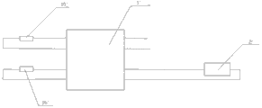
Fig. 1 is the operating circuit schematic diagram of a typical temperature and humidity controller control dehumidifying well heater;
Fig. 2 is an operating circuit schematic diagram of the present invention.
Embodiment
Embodiment 1
A kind of substation equipment drives damp well heater on-line monitoring module, as shown in Figure 2, is connected in series an on-line monitoring module 3 between temperature and humidity controller 1 and well heater 2 loops, and temperature sensor 15, humidity sensor 16 also are installed in the loop; Described on-line monitoring module 3 comprises the magnet ring current transformer 4 of being with winding, low-power ground fault interruption device integrated circuit 5, first electric capacity, 6, the second electric capacity, 7, the three electric capacity 8, first resistance 9, second resistance, 10, the three resistance, 11, the four resistance 12, light emitting diode 13, bridge rectifier diode 14; Wherein be connected in series magnet ring current transformer 4 in well heater 2 loops on any lead with winding, the magnet ring current transformer 4 and first electric capacity 6 of band winding are of coupled connections, first electric capacity 6 is connected with first input, 51 ends of low-power ground fault interruption device integrated circuit 5, the magnet ring current transformer 4 of band winding is connected with second input end 52 of low-power ground fault interruption device integrated circuit 5, and the 3rd input end 53 of low-power ground fault interruption device integrated circuit 5 is connected with the first input end 141 of bridge rectifier diode 14; Be serially connected with first resistance 9 between the first input end 51 of low-power ground fault interruption device integrated circuit 5 and first output terminal 54, second input end 55 of low-power ground fault interruption device integrated circuit 5 is serially connected with second resistance, 10, the three resistance, 11, the three electric capacity 8; The 3rd input end 56 of low-power ground fault interruption device integrated circuit 5 is serially connected with second electric capacity 7; Wherein the 4th resistance 12 and light emitting diode 13 series connection backs are connected in parallel with second electric capacity 7, are serially connected in afterwards between the first input end 141 of the 3rd input end 56 of low-power ground fault interruption device integrated circuit 5 and bridge rectifier diode 14; The 3rd electric capacity 8 is serially connected on second input end 142 of bridge rectifier diode 14; First output terminal 143 of bridge rectifier diode 14 is connected with output terminal with the input end of well heater 2 respectively with second output terminal 144.
Among the figure, low-power consumption ground fault interruption device integrated circuit 5 adopts CL4145, is low-power consumption ground fault interruption device integrated circuit (Microtronics A/S provides by Shenzhen lattice), and this circuit need not external voltage stabilizer, obtain 26V working power voltage, adjustable sensitivity from alternating current.
The magnet ring current transformer 4 of band winding, any lead seals in this magnet ring that has winding in the well heater loop, in case flow through in the lead greater than the electric current more than the 20mA, the alternating flux of in magnet ring, being responded to, to make the winding that is wound on this magnet ring induce small exchange current, this electric current is through the coupling of first electric capacity 6, be input in the CL4145 low-power consumption ground fault interruption device integrated circuit 5, and through after the multistage amplification, at the Led of this circuit Output pin, said the 3rd output terminal of the present invention just 56 output dc voltages, luminous for driven for emitting lights diode 13, the well heater loop has electric current to flow through to indicate at that time, and expression well heater 2 is working properly.
Second electric capacity 7 is ultrasonic filter electric capacity in the present embodiment, its size is used for the stability of controlling and driving light emitting diode 13 operating voltage, first resistance 9 is used for regulating the sensitivity of low-power consumption ground fault interruption device integrated circuit 5, second resistance, 10, the three resistance 11 are dropping resistor, and power should be selected 1W, the 3rd electric capacity 8 withstand voltage electric capacity of the dacron that should elect 630V as, first electric capacity, 6, the second electric capacity 7 are preferably leaded multilayer ceramic capacitor, and withstand voltage need are greater than getting final product more than the 10V.For reducing power consumption, light emitting diode 13 should be selected superhigh brightness LED for use in addition, and its current-limiting resistance is chosen as 2k Ω, and magnet ring is selected getting final product of high permeability for use.