CN102166131A - Device, system, and method for forming a cavity in and delivering a curable material into bone - Google Patents
Device, system, and method for forming a cavity in and delivering a curable material into bone Download PDFInfo
- Publication number
- CN102166131A CN102166131A CN2011100495937A CN201110049593A CN102166131A CN 102166131 A CN102166131 A CN 102166131A CN 2011100495937 A CN2011100495937 A CN 2011100495937A CN 201110049593 A CN201110049593 A CN 201110049593A CN 102166131 A CN102166131 A CN 102166131A
- Authority
- CN
- China
- Prior art keywords
- sleeve pipe
- bone
- distal portion
- guide pipe
- deformable segments
- Prior art date
- Legal status (The legal status is an assumption and is not a legal conclusion. Google has not performed a legal analysis and makes no representation as to the accuracy of the status listed.)
- Pending
Links
Images


Classifications
-
- A—HUMAN NECESSITIES
- A61—MEDICAL OR VETERINARY SCIENCE; HYGIENE
- A61B—DIAGNOSIS; SURGERY; IDENTIFICATION
- A61B17/00—Surgical instruments, devices or methods, e.g. tourniquets
- A61B17/56—Surgical instruments or methods for treatment of bones or joints; Devices specially adapted therefor
- A61B17/58—Surgical instruments or methods for treatment of bones or joints; Devices specially adapted therefor for osteosynthesis, e.g. bone plates, screws, setting implements or the like
- A61B17/88—Osteosynthesis instruments; Methods or means for implanting or extracting internal or external fixation devices
- A61B17/8802—Equipment for handling bone cement or other fluid fillers
- A61B17/8805—Equipment for handling bone cement or other fluid fillers for introducing fluid filler into bone or extracting it
- A61B17/8819—Equipment for handling bone cement or other fluid fillers for introducing fluid filler into bone or extracting it characterised by the introducer proximal part, e.g. cannula handle, or by parts which are inserted inside each other, e.g. stylet and cannula
-
- A—HUMAN NECESSITIES
- A61—MEDICAL OR VETERINARY SCIENCE; HYGIENE
- A61B—DIAGNOSIS; SURGERY; IDENTIFICATION
- A61B17/00—Surgical instruments, devices or methods, e.g. tourniquets
- A61B17/56—Surgical instruments or methods for treatment of bones or joints; Devices specially adapted therefor
- A61B17/58—Surgical instruments or methods for treatment of bones or joints; Devices specially adapted therefor for osteosynthesis, e.g. bone plates, screws, setting implements or the like
- A61B17/88—Osteosynthesis instruments; Methods or means for implanting or extracting internal or external fixation devices
- A61B17/8802—Equipment for handling bone cement or other fluid fillers
- A61B17/8805—Equipment for handling bone cement or other fluid fillers for introducing fluid filler into bone or extracting it
- A61B17/8811—Equipment for handling bone cement or other fluid fillers for introducing fluid filler into bone or extracting it characterised by the introducer tip, i.e. the part inserted into or onto the bone
-
- A—HUMAN NECESSITIES
- A61—MEDICAL OR VETERINARY SCIENCE; HYGIENE
- A61B—DIAGNOSIS; SURGERY; IDENTIFICATION
- A61B17/00—Surgical instruments, devices or methods, e.g. tourniquets
- A61B17/16—Bone cutting, breaking or removal means other than saws, e.g. Osteoclasts; Drills or chisels for bones; Trepans
- A61B17/1604—Chisels; Rongeurs; Punches; Stamps
-
- A—HUMAN NECESSITIES
- A61—MEDICAL OR VETERINARY SCIENCE; HYGIENE
- A61B—DIAGNOSIS; SURGERY; IDENTIFICATION
- A61B17/00—Surgical instruments, devices or methods, e.g. tourniquets
- A61B17/16—Bone cutting, breaking or removal means other than saws, e.g. Osteoclasts; Drills or chisels for bones; Trepans
- A61B17/1662—Bone cutting, breaking or removal means other than saws, e.g. Osteoclasts; Drills or chisels for bones; Trepans for particular parts of the body
- A61B17/1671—Bone cutting, breaking or removal means other than saws, e.g. Osteoclasts; Drills or chisels for bones; Trepans for particular parts of the body for the spine
-
- A—HUMAN NECESSITIES
- A61—MEDICAL OR VETERINARY SCIENCE; HYGIENE
- A61B—DIAGNOSIS; SURGERY; IDENTIFICATION
- A61B17/00—Surgical instruments, devices or methods, e.g. tourniquets
- A61B17/34—Trocars; Puncturing needles
- A61B17/3417—Details of tips or shafts, e.g. grooves, expandable, bendable; Multiple coaxial sliding cannulas, e.g. for dilating
- A61B17/3421—Cannulas
-
- A—HUMAN NECESSITIES
- A61—MEDICAL OR VETERINARY SCIENCE; HYGIENE
- A61B—DIAGNOSIS; SURGERY; IDENTIFICATION
- A61B17/00—Surgical instruments, devices or methods, e.g. tourniquets
- A61B17/34—Trocars; Puncturing needles
- A61B17/3472—Trocars; Puncturing needles for bones, e.g. intraosseus injections
-
- A—HUMAN NECESSITIES
- A61—MEDICAL OR VETERINARY SCIENCE; HYGIENE
- A61B—DIAGNOSIS; SURGERY; IDENTIFICATION
- A61B17/00—Surgical instruments, devices or methods, e.g. tourniquets
- A61B17/00234—Surgical instruments, devices or methods, e.g. tourniquets for minimally invasive surgery
- A61B2017/00292—Surgical instruments, devices or methods, e.g. tourniquets for minimally invasive surgery mounted on or guided by flexible, e.g. catheter-like, means
- A61B2017/003—Steerable
- A61B2017/00318—Steering mechanisms
- A61B2017/00331—Steering mechanisms with preformed bends
-
- A—HUMAN NECESSITIES
- A61—MEDICAL OR VETERINARY SCIENCE; HYGIENE
- A61B—DIAGNOSIS; SURGERY; IDENTIFICATION
- A61B17/00—Surgical instruments, devices or methods, e.g. tourniquets
- A61B2017/0042—Surgical instruments, devices or methods, e.g. tourniquets with special provisions for gripping
- A61B2017/00455—Orientation indicators, e.g. recess on the handle
-
- A—HUMAN NECESSITIES
- A61—MEDICAL OR VETERINARY SCIENCE; HYGIENE
- A61B—DIAGNOSIS; SURGERY; IDENTIFICATION
- A61B17/00—Surgical instruments, devices or methods, e.g. tourniquets
- A61B2017/00831—Material properties
- A61B2017/00867—Material properties shape memory effect
-
- A—HUMAN NECESSITIES
- A61—MEDICAL OR VETERINARY SCIENCE; HYGIENE
- A61B—DIAGNOSIS; SURGERY; IDENTIFICATION
- A61B90/00—Instruments, implements or accessories specially adapted for surgery or diagnosis and not covered by any of the groups A61B1/00 - A61B50/00, e.g. for luxation treatment or for protecting wound edges
- A61B90/06—Measuring instruments not otherwise provided for
- A61B2090/062—Measuring instruments not otherwise provided for penetration depth
Landscapes
- Health & Medical Sciences (AREA)
- Life Sciences & Earth Sciences (AREA)
- Orthopedic Medicine & Surgery (AREA)
- Surgery (AREA)
- Medical Informatics (AREA)
- Engineering & Computer Science (AREA)
- Biomedical Technology (AREA)
- Heart & Thoracic Surgery (AREA)
- Nuclear Medicine, Radiotherapy & Molecular Imaging (AREA)
- Molecular Biology (AREA)
- Animal Behavior & Ethology (AREA)
- General Health & Medical Sciences (AREA)
- Public Health (AREA)
- Veterinary Medicine (AREA)
- Surgical Instruments (AREA)
- Prostheses (AREA)
Abstract
The invention discloses a device, system and method for forming a cavity in and delivering a curable material into bone. A curable material delivery cannula device is disclosed. The device includes a cannula and a hub. The cannula includes an open proximal end, a deflectable segment forming a pre-set curve, a lumen, and side orifice(s) adjacent, and proximally spaced from, the distal end and fluidly connected to the lumen. When inserted within a guide cannula, the deflectable segment straightens. When distally extended from the guide cannula, the deflectable segment reverts to the curved shape. The distal end has a blunt tip for non-traumatic interface with bodily material. During use, curable material, such as bone cement, is delivered from the side orifice(s) in a radial direction relative to the lumen. The device may be used to create voids for receiving curable material, and may include spacers configured to control location and/or orientation of the voids.
Description
It is 200880011416.6 that the application is based on application number, and the applying date is on October 9th, 2009, and the application people be John A Krueger and Ai Wen D Lin Deman, is entitled as to be used for rectification material transfer dividing an application to the device of bone, system and method.
The present invention is that the name of application on November 18th, 2005 is called the U.S. Patent application No.11/282 of " being used for correcting device, the system and method for material transfer to bone ", and 102 continuation is partly applied for, by reference it is incorporated into this in full.
Technical field
The present invention relates to be used for the apparatus and method of firm bony structure.More specifically, the present invention relates to be used for rectifiable robust material is delivered to device, the system and method for bony structure.
Background technology
The surgical operation therapy of the bony site that has proved damage or loosened is very favorable to patient (patient who for example, has the backache relevant with spinal cord injury).
The bone of human skeletal system can be categorized into two form groups generally: " cortex " bone and " spongiosa " bone.All bones outer wall constitute by cortical bone, cortical bone has the compact bone structure, it is characterized in that micropipe.The interior tissue of spongy bone or " girder " bone formation bone.Spongy bone is made of the elongate rod of interconnection and the grid of plate, and the term of the elongate rod of interconnection and the grid of plate is " girder ".
In some bone surgery process, (palliative) (or treatment) material of appeasing that is used for firm girder by injection replenishes spongy bone.For example, the vertebra up and down in the spine can by injection suitably, treatment material (for example, PMMA or other bone cement) and advantageously firm.In other operation, verified, for example the robust material percutaneous injection is helped alleviating pain and firm damaged bone position in the vertebra pressure fissure by pedicle or pedicle of vertebral arch mean of access.The bone of other skeleton (for example, femur) can be treated with similar manner.From anyways, general bone or concrete spongy bone can be by appeasing that injection bone compatible material be reinforced and firm.
The traditional method that is used to transmit the bone robust material must use brill (perhaps cutting) to wear straight-through road device or the sleeve pipe of cortical bone with the path that acquires the spongy bone position.The bone robust material is driven through sleeve pipe then to fill the spongy bone part at bony site place.In order to minimize the wound of operation, sleeve pipe is the little pin of diameter normally.
Under above-mentioned situation, because needle tubing contacts with gas soft tissue structure with spongy bone, the following initial needle tubing that inserts of existence may puncture or puncture other tissue of reparation and/or the inherent danger of bone amount (away from the insertion section bit position).Therefore, in percutaneous vertebroplasty process, need carry out carefulness and look after, puncture, puncture or make the vertebra main body break avoiding.In other inner bone prosthesis, propose similar back and inserted the puncture worry.Along these identical routes, in order to minimize the wound and the time of finishing operation, expectation is only carried out single bony site and is inserted.Unfortunately, for many operations, use traditional staight needle pipe can not arrive the surgical site of being discussed fully.For example, use vertebroplasty, the closure property of inner vertebra main body often need be used twice or more times insertion (" bilateral " technology) of staight needle pipe in different vertebras approximated position.Expectation is provided for transmitting the system of bone robust material, and it can satisfy the dissection requirement at special transmission position easilier, for example, can promote the system through the pleurocentrum plasty.
Apparatus under OSTEO-RX (TM) product line that the Cook medical company is sold utilizes the bone robust material of looper transmission as the parts of vertebroplasty or similar operation.It is said that looper improves the surgeon location and robust material is injected at the ability of desired site (site).Be similar to traditional staight needle pipe, looper distributes the rectification material by the single axially open of most distal end tip.But looper is used in combination with trocar sheath, and trocar sheath is generally auxiliary to be established to the path of bony site and to be convenient to pin and be delivered to (in the bone) transmission position with expectation mode percutaneous.More specifically, trocar sheath at first acquires the path of bony site, and then pin slides by the far-end that carries out of trocar sheath.In case needle point distad extends to the end of trocar sheath, then needle point exposes with respect to bony site.For fear of puncture when inserting the distal tip of pin in the bony site and latent lesion tissue thus, it is interior and extend away from distal tip to need that other line parts are arranged in pin vertically.Interior lines " protection " tissue or other bodily tissue avoid the distal tip of wound contact pin when the tip, location.Before inculcating the bone robust material, must remove coaxial line by pin.In addition, the axially open that pin can only pass through the distal tip place of pin distributes robust material, and perhaps this hinder the surgeon to inculcate all desired region and/or needle point " need be retreated " the extra operating procedure that transmits the position away from expectation.In addition, because needle point (and axially open) thus probably or in the face of bone to be repaired damaged (for example, crack in the vertebra main body), robust material can direct injection at damaged place, this produces robust material and forces to advance by damaged or from damaged outwards progressive obvious probability.This does not obviously expect.The problems referred to above described in the context of percutaneous cone plasty and worry also produce in the surgical operation at similar other bony site place.
Verified, material is expelled to loss or loose bony site is extremely beneficial to the patient with appeasing.But the known path or the technology of inculcating make spininess rod and/or dangerous puncture bone or tissue necessitate.Therefore, there is demand in modifying device and the system that is used for robust material is delivered to loss or loose bony site.
Summary of the invention
Be included in the bone in the operation process in needs additional components (such as independent line) not according to the advantage that principle disclosed by the invention obtained the transmission sleeve pipe of non-wound is provided, minimize the puncture tissue or puncture the blunt distal portion of bone or tissue.Other advantage relates to contiguous blunt distal portion and limits at least one side opening, and wherein, the hole allows the position in bone radially to inculcate the rectification material, though in distal portion with bone and/or organize under the situation about contacting.Therefore, appeasing osseous surgery can still less finish near under the situation of bony site in operating room time that shortens and surgical device.For example, finish easily through the pleurocentrum plasty.In addition, in fact can be near any zone in the surgical site.In addition, can force under the situation that advances to or pass anatomical features, transmit telescopic distal portion and can be placed to the concrete anatomical features (for example, crack) of close surgical site as far as possible as required at the material of not worrying subsequent delivery.
Aspects more of the present invention relate to and are used for and will correct the transmission casing bit of material transfer to bone.This device comprises the hub that transmits sleeve pipe and form fluid port.Transmit sleeve pipe and limit close end, deformable segments, distal portion, chamber and at least one side opening.Near-end is vertically to the chamber opening.Deformable segments forms relative with close end and ends at the distal portion of sealing vertically.In addition, distal portion has blunt tip.The chamber is connected from the close end extension and with the side opening fluid.In this regard, side opening adjacent distal end portion forms and is spaced apart at nearside and distal portion.At last, deformable segments forms the curved shape that extends longitudinally, and has shape memory characteristic.Under the situation of this structure, deformable segments can be forced into straight substantially shape and return to curved shape naturally when removing power.The hub fluid is coupled to and transmits telescopic close end.Under the situation of this structure, in use, in the time of in the transmission position of distal portion in inserting bone because blunt tip and the tissue that do not damage or puncture.In addition, side opening provides no matter whether distal portion is injected the body material and will be injected the ability of correcting material, and obtains to distribute more completely.
Others of the present invention relate to corrects the material transfer system in a kind of bone, and it is used for correcting material such as bone cement with correcting the transmission position of material transfer in the bone.This system comprises transmission sleeve pipe and hub and guide pipe as above.The size of transmitting sleeve pipe and guide pipe make transmit sleeve pipe in guide pipe slidably.Be deformed into straight substantially shape when in this regard, deformable segments is configured in being inserted into sleeve pipe and when extending away from guide pipe, revert to curved shape with transmission rectification material.In this embodiment, guide pipe and the telescopic size of transmission are suitable for forming the vertebroplasty operation.
Others of the present invention relate to the method for the bone structure of firm human patients.The method comprises provides the sleeve pipe of transmission as above.The distal tip of guide pipe is positioned in the bone structure.Transmitting sleeve pipe inserts in the guide pipe.In this regard, deformable segments becomes straight substantially shape in the guide pipe internal strain.Transmit sleeve pipe and advance with respect to guide pipe, make that distal portion and the telescopic at least a portion deformable segments of transmission are outstanding away from the distal tip of guide pipe at far-end.In this regard, the part away from the distal tip of guide pipe returns to curved shape naturally in the deformable segments.Spots localization is transmitted in the expectation of transmitting in the telescopic distal portion adjacent bone structure.To correct material is expelled in the chamber.The rectification material of injection is delivered to by side opening and transmits the position.In case transmit, correct material and allow to solidify, with firm bone structure.In one embodiment, this method also comprises with respect to the guide pipe rotation transmits sleeve pipe, to change the locus of side opening, is provided at the ability that material is corrected in the Different Plane injection thus.
Another aspect of the present invention relates to the method that the rectification material is expelled to the transmission position in the bone structure.This method comprises providing transmits telescopic step, and this transmissions sleeve pipe has opening, close end, relative with close end and have the deformable segments of distal portion and from the chamber of close end extension.Deformable segments has shape memory characteristic, and extends longitudinally nature and present curved shape.This method comprises that also the distal tip with guide pipe is positioned at the step in the bone structure.This method also comprises the step of described transmission sleeve pipe being inserted described guide pipe, and wherein deformable segments becomes straight substantially shape in the guide pipe internal strain, and makes distal portion and at least a portion deformable segments give prominence to away from distal tip at distal advancement transmission sleeve pipe.Part away from the distal tip of guide pipe in the deformable segments returns to curved shape then naturally.This method comprises that also operation transmits sleeve pipe and make the step that produces one or more cavities in the soft tissue of at least a portion deformable segments in bone structure.This method also comprises and will correct material transfer to the step of transmitting the position, wherein, correct material transfer in the soft tissue by one or more cavities that deformable segments produced.
Another aspect of the present invention relates to and is expelled to method in the bone structure with correcting material.This method comprises providing transmits telescopic step, and this transmissions sleeve pipe has opening, close end, relative with close end and have the deformable segments of distal portion and from the chamber of close end extension.Deformable segments has shape memory characteristic, and extends longitudinally nature and present curved shape.In the method, the distal tip of guide pipe is positioned in the bone structure.To transmit sleeve pipe and insert in the guide pipe, and it is characterized in that, deformable segments becomes straight substantially shape in the guide pipe internal strain.Transmit sleeve pipe in distal advancement, make distal portion and at least a portion deformable segments outstanding, it is characterized in that the part away from distal tip in the deformable segments returns to curved shape naturally away from distal tip.Distal portion distad is positioned at contiguous first area of transmitting in the position.To correct material transfer then to the first area of transmitting in the position.Distal portion is contiguous then to be transmitted the second area location in the position and corrects material transfer to the second area that transmits in the position.
Another aspect of the present invention relates to a kind of casing bit of material transfer to bone that be used for correcting, and it corrects material such as bone cement as a part of correcting the material transfer system.This device comprises the transmission sleeve pipe that is loaded with bone cement in advance, and this transmission sleeve pipe limits opening, close end, relative with close end and end at the deformable segments of closed distal end portion.This device comprises the chamber of extending from close end.This device comprises also that adjacent distal end portion forms and at nearside and isolated at least one side opening of distal portion, side opening is connected with the chamber fluid, wherein, deformable segments forms the curved shape that extends longitudinally, and have shape memory characteristic, make deformable segments be formed at and longitudinally present straight substantially form and when removing power, return to curved shape naturally when stressed.
Another aspect of the present invention relates to corrects the material transfer system in a kind of bone, and it is used for correcting material such as bone cement with correcting the transmission position of material transfer in the bone.This system comprises the transmission sleeve pipe, this transmission sleeve pipe has opening, close end, relative with close end and have the deformable segments of distal portion and a chamber of extending from close end, wherein, deformable segments ends at distal portion, wherein, deformable segments has shape memory characteristic, and extends longitudinally nature and present curved shape.This system also comprises guide pipe, the internal diameter of guide pipe is greater than transmitting telescopic external diameter, and has the open distal end tip, wherein, deformable segments is configured to may be deformed to straight substantially shape, make to transmit sleeve pipe in guide pipe slidably, and when extending away from distal tip will correct material transfer by distal portion in implant site the time, deformable segments returns to curved shape naturally, and wherein, transmitting sleeve pipe can smooth sliding in guide pipe.
Another aspect of the present invention relates to the rectification material structure of firm vertebra main body.This structure comprises that first corrects the material deposition, and the soleplate that it is adjacent to the vertebra main body is used to first soleplate of vertebra main body to provide support.This structure comprises that second corrects the material deposition, and the soleplate that it is adjacent to the vertebra main body is used to second soleplate of vertebra main body to provide support.This structure also comprises the rectification material post of correcting between the material deposition and the second rectification material deposition first, and it provides support for the vertebra main body.
Description of drawings
Comprise accompanying drawing so that the understanding of the present invention further to be provided, and accompanying drawing comprises in this manual and the part of book as an illustration.Recognize other embodiments of the invention and many expection advantages of the present invention easily, because they are by understanding better with reference to following detailed description.Do not draw to scale between the element of accompanying drawing.Similar Reference numeral is represented corresponding similar parts.
Fig. 1 illustrates the interior parts of correcting the material transfer system of bone in accordance with the principles of the present invention;
Fig. 2 A is that the cuing open of transmission casing bit parts of the system of Fig. 1 shown exploded view;
Fig. 2 B is the transmission sleeve pipe of Fig. 2 A device and the front view of hub part;
Fig. 3 A is the amplification view of the telescopic distal portions of transmission of Fig. 2 A;
Fig. 3 B is the telescopic cutaway view of the transmission of Fig. 3 A;
Fig. 3 C is the amplification view of the telescopic distal portions of the transmission among Fig. 2 A another preferred embodiment according to the present invention;
Fig. 3 D is the amplification view of the telescopic distal portions of the transmission among Fig. 2 A another preferred embodiment according to the present invention;
Fig. 3 E is the amplification view of the telescopic distal portions of the transmission of Fig. 2 A another preferred embodiment according to the present invention;
Fig. 4 is the cutaway view after the last assembling of the transmission casing bit of Fig. 2 A;
Fig. 5 is the side view of optional in accordance with the principles of the present invention transmission casing bit;
Fig. 5 A is the side view of optional in accordance with the principles of the present invention transmission casing bit;
Fig. 5 B is the side view of optional in accordance with the principles of the present invention transmission casing bit;
Fig. 6 A is used to appease the reduced graph of correcting the material transfer system in the bone of osseous surgery according to the principle of the invention;
Fig. 6 B is the cutaway view of a part in the system of Fig. 6 A;
The final stage of the operation that system carried out of Fig. 6 C pictorial image 6A;
Fig. 6 D is the cross-sectional view of a part and vertebra main body in the system of 6A, and its diagram is corrected the injection of material;
Fig. 6 E is the cross-sectional view of vertebra main body, and it illustrates according to the available various cone plastys of principle of the invention approximated position;
Fig. 7 A and 7B are the preceding bitmaps of the simplification of vertebra main body, and it illustrates the use of system in accordance with the principles of the present invention;
Fig. 8 A and 8B are the simplified side view of vertebra main body, and it illustrates the use of system in accordance with the principles of the present invention;
Fig. 9 is the simplified side view of vertebra main body, and it illustrates the use of system in accordance with the principles of the present invention;
Figure 10 is the simplified side view of vertebra main body, and it illustrates the use of system in accordance with the principles of the present invention;
Figure 11 A-11C is the preceding bitmap of the simplification of vertebra main body, and it illustrates the use of system in accordance with the principles of the present invention; And
Figure 12 is the preceding bitmap of the simplification of rumpbone, and it illustrates the use of system in accordance with the principles of the present invention.
The specific embodiment
Fig. 1 illustrates the interior parts of correcting material transfer system 20 of bone in accordance with the principles of the present invention.System 20 comprises outer catheter 22 and transmits sleeve pipe 26 (total Reference numeral).The detailed description of various parts is provided below.But in general, the size of transmitting the part in the casing bit 26 is suitable for slidably being arranged in the conduit 22, and conduit 22 is suitable for being used for forming and/or locating the expectation transmission position of inside bone in addition.In case the location is used transmission casing bit 26 that rectifiable bone robust material is expelled to and is transmitted the position.System 20 can be used for many different operations, for example comprises: cone plasty or correct wherein that material is passed to the inside bone position and take out other bone of extracting material out in the back from the inside bone position and strengthen operation.
In these cases down, outer catheter 22 generally can be routed to interested bony site with transmitting casing bit 26, and can present various forms thus.But in general, the size of guide pipe 22 is suitable for slidably receiving a part of transmitting casing bit 26, ends at the distal tip 28 of opening.Distal tip 28 can also be suitable for the puncture of convenient osseous tissue, such as transmit the position when using guide pipe 22 to form in bone.In order to promote in use to be inserted into slidably in guide pipe 22 and the transmission casing bit 26 the expectation interface between the part in the guide pipe 22, in one embodiment, the inside diameter surface of guide pipe 22 is very smooth, reach tarnish or mirror finish (for example, the mean-square value of about 0-16 (RMS) scope).In a further advantageous embodiment, the external diameter surface of the inside diameter surface of guide pipe or transmission sleeve pipe 36 can be coated with polytetrafluoroethylene, inserts the expectation smooth interface between the part in the guide pipe 22 to promote in use can slide in guide pipe 22 and the transfer tube device 26.Between guide pipe 22 and transmission casing bit 26, also can use the polytetrafluoroethylene sleeve.In addition, the external diameter surface that transmits sleeve pipe 36 can polish with very smooth to tarnish or mirror finish (that is the RMS scope of about 0-16).In any case in certain embodiments, guide pipe 22 can be attached to the lever 30 of the ability that is used to strengthen surgeon's operating system 20 at its near-end.Alternatively, can cancel lever 30.
Transmit casing bit 26 and illustrate in greater detail in Fig. 2 A, it comprises lever assembly 32 (total Reference numeral), hub 34 generally and transmits sleeve pipe 36.Keep hub 34/ to transmit under the situation of sleeve pipe 36 combinations at lever assembly 32, hub port 34 forms fluid port and is connected with transmission sleeve pipe 36 fluids.As described in more detail below, the size of transmitting sleeve pipe 36 is suitable for coaxial slidably being received in the guide pipe 22 (Fig. 1), and is suitable for transmitting the rectification material that is injected at wherein by hub 34.
In one embodiment, lever 40 comprises first 44 and second portion 46.First 44 is suitable for assembly slipped into and is coupled to second portion 46, such as annular projection 48 and the groove 50 by complementary (complimentary).In any case first 44 is formed with the central passage 52 that extends internally from its outer surface 54.
Second portion 46 limits internal holes 56, and under the situation of lever 40 last assemblings, internal holes 56 is aimed in central passage 52.Hole 56 can present various forms, and its size is suitable for receiving hub 34 with nested mode.Nested interface between lever 40 and the hub 34 can not be with respect to lever 40 rotations (promptly under the hub 34 assembling situations in the end preferably suitable for making, the opposing of hub 34/ lever 40 interfaces is applied to the moment of torsion on any parts, make rotatablely moving of lever 40 cause the identical rotation of hub 34/ transmission sleeve pipe 36, even when transmission sleeve pipe 36 inserts in the surgical site that seals).Therefore, in one embodiment, the cross section of hole 56 and hub 34 (as described below) has corresponding asymmetric or non-circular shape.With respect to the longitudinal sectional view of Fig. 2 A, the non-circular shape in hole 56 is characterised in that hole 56 is limited by sidewall 58, and this sidewall 58 has the shoulder corresponding with the shape of following hub in greater detail 34 60.Alternatively, sidewall 58 can present various other structures.In any case in one embodiment, second portion 46 is formed with external screw thread 62.
Keeper 42 is configured to that hub 34/ is transmitted sleeve pipe 36 and is fixed to lever 40, and is formed with the central opening 64 that limits proximal part 66 and distal portions 68.Proximal part 66 is formed with the central opening 64 of diameter less times greater than hub 34, and has the female thread 70 that size is suitable for carrying out with the external screw thread 62 of lever 40 threads engage.Distal portions 68 is formed with opening 64, and its diameter is rigidly connected to provide more between lever assembly 32 and hub 34/ transmission sleeve pipe 36 near the external diameter that transmits sleeve pipe 36.Alternatively, lever assembly 32 can present various other forms, and can fully phase out in certain embodiments.
In one embodiment, hub 34 is the conventional fluid port design, and limits fluid passage 71 and be positioned at external screw thread 72 on its close end 74.In one embodiment, screw thread 72 is two-wire dextrorotation Rule (Luer) screw threads that comprise 5 millimeters helical pitches, but other helicitic texture and helical pitch size also are acceptables.In any case as mentioned above, in one embodiment, hub 34 is formed at can be with respect to 32 rotations " locked " of lever assembly under the situation after the final assembling.Therefore, in one embodiment, the main body of hub 34 forms roughly periphery 76, and the part of this periphery 76 flattens in zone 78, shown in Fig. 2 B.Flatten zone 78 size and dimension corresponding to the hole sidewall 58 (Fig. 2 A) that is arranged on the lever 40 (Fig. 2 A).
In one embodiment, hub 34 is formed by sterilizable polymeric material.By example, hub 34 can be formed by polylac 717C acrylonitrile-butadiene-styrene (ABS) (ABS) copolymer, but other sterilizable polymer and/or copolymer also are acceptables.
In a further advantageous embodiment, removable lid 38 fluid passage 71 that is suitable for being attached to the first 44 of lever assembly 32 and covers hub 34.When transmission sleeve pipe 36 was inserted in the guide pipe 22, blood or other fluid can advance in transmitting sleeve pipe 36 and leave by the fluid passage 71 of hub 34.When transmission sleeve pipe 36 was incorporated into guide pipe 22, removable lid 38 can be attached to lever assembly 32.After will transmitting sleeve pipe 36 and being inserted into desired locations, remove removable lid 38, to allow the path of hub 34.
Return Fig. 2 A, transmit sleeve pipe 36 and limit close end 80 and distal portion 82, and adjacent distal end portion 80 is formed with the one or more side openings 84 that are communicated with inner chamber 86 fluids.In addition, transmit sleeve pipe 36 and comprise the deformable segments 88 (total Reference numeral) that limits default curved or bending section 90.As described below, deformable segments 88, particularly bending section 90 comprises distal portion 82 or extends from distal portion 82, and has the shape memory attribute, deformable segments 88 can be forced to straight substantially shape from curved shape (shown in Fig. 2 A) thus, and returns to curved shape under the situation of power naturally removing.
With reference to Fig. 2 A and 2B, side opening 84 adjacent distal end portions 82 form, and it extends through the side thickness that transmits sleeve pipe 36.In one embodiment, single hole 84 is set, and hole 84 is positioned to opposite with the direction of bending section 90.In other words, with respect to the longitudinal sectional view of Fig. 2 A, the direction of bending section 90 is used to form transmits sleeve pipe 36, to limit inflection side 102 and excurvation side 104.Under the situation of these labels, side opening 84 is along 104 formation of excurvation side and with respect to excurvation side 104 openings.Find surprisingly that by side opening 84 being positioned to and bending section 90 " opposite ", user can be felt correcting the control raising of material from transmission sleeve pipe 36 assign direction.Alternatively, the side opening 84 of bigger quantity can be set, it can or can be along circumferential alignment, and can or can be along excurvation side 104 location of transmitting sleeve pipe 36.In general, side opening 84 is offset distance D 1 at least from distal portion 82.In one embodiment, distance D 1 is between 0.05 inch and 0.5 inch, and preferably, distance D 1 is between 0.1 inch and 0.25 inch.Under this structure, even when tissue or bone are pressed in blunt tip 100, side opening 84 is for " opening " and can be used for distribution (or suction) material thus.In addition, side opening 84 provides distribution radially or the flow direction with respect to the longitudinal axis that transmits sleeve pipe 36.
Side opening 84 can (with respect to the outer surface that transmits sleeve pipe 36) present different shape and size.For example, side opening 84 can be ellipse, circle, shaped form etc.In one embodiment, with reference to Fig. 3 A, can form chamfered area 106 around side opening 84, to reduce sharp edges along the outside of transmitting conduit 36 and to promote from consistent the flowing of rectification material of side opening 84 (the extending bore size that is realized via chamfered area 106).At side opening 84 is among the non-circular embodiment, limiting hole length L and width W.In this regard, length L is preferably greater than 0.075 inch, more preferably greater than 0.100 inch greater than 0.050 inch.Though the width W of side opening 84 can maybe (for example can be not less than length L, 0.042 inch magnitude in one embodiment), suitably being characterised in that of side opening 84 is very big, especially with only provides traditional bone cement transmission pin of axial hole or opening to compare at distal tip.
Particularly, in addition with reference to Fig. 3 B (its diagram is passed side opening 84 and the cutaway view of the transmission sleeve pipe 36 got), transmit sleeve pipe 36 and limit inner diameter, ID (that is the diameter in chamber 86).Side opening 84 is connected with chamber 86 fluids and extends with radial manner.Under the situation of these regulations, in one embodiment, the length L of side opening 84 is greater than the inner diameter, ID of transmitting sleeve pipe 36.Like this, at least one linear dimension of side opening 84 is supposed to form hole (that is, extending axially the hole) in distal portion 82 greater than any hole dimension that can obtain.That is to say that the inner diameter, ID that the size that is formed at the hole that distal portion 82 places that transmit sleeve pipe 82 form (using as transmit tradition in the pin field at bone cement) is transmitted sleeve pipe 36 limits.On the contrary, side opening 84 must be very big in accordance with the principles of the present invention, and this shows and distinct advantage when attempting using it by low viscous flow body (such as the rectification material of bone cement).
With reference to Fig. 3 C-3E, except the rounded distal portion 82 shown in Fig. 3 A, the closed distal end portion 82 that transmits sleeve pipe 36 can show many different structures.Closed distal end portion 82 also can be generally flat tip (shown in Fig. 3 C), sharp " trocar " tip (shown in Fig. 3 D) or sharp " pencil " tip (shown in Fig. 3 E).Flat tip helps reducing the danger of piercing through soma.On the contrary, when needs, sharp tip is configured with to be beneficial to and allows doctor's use will transmit sleeve pipe 36 pushing body tissues than blunt tip power still less.
Return Fig. 2 A, in one embodiment, transmit the continuous length that sleeve pipe 36 limits between close end 80 and distal portion 82, and deformable segments 88 (particularly, bending section 90) from 25% (wherein, " length " of transmission sleeve pipe 36 be the length of in the end assembling situation under from hub 34 extending) of distal portion 82 extensions near length.In being suitable for other operating other embodiment, deformable segments 88 (particularly, bending section 90) is measured the 10%-50% that extends the length of transmitting sleeve pipe 36 from distal portion 82.
Be delivered to sealing position in the bone (such as, vertebroplasty operation) for the ease of correcting material (for example, bone cement), deformable segments 88 can form the predetermined bend radius R place qualification bending section 90 with the operation of being discussed being suitable for.In one embodiment, bending section 90 is that J-shaped shape (at least near 90 degree crooked) and the radius of curvature R that limits are less than 1.5 inches, preferably in the scope of 0.25-1.5 inch.In a preferred embodiment, bending section 90 is defined as radius of curvature R near 1 inch.Alternatively, following more detailed description, radius of curvature R can be greater or lesser, and this depends on the concrete operation of using transmission sleeve pipe 36.
In addition, for the ease of deformable segments 88 from curved warpage to straight substantially state (such as, outside traditional sleeve 36 is inserted in the guide pipe 22 time (Fig. 1)) and return to curved shape, transmit sleeve pipe 36 (or deformable segments 88) at least and form by shape memory metal.In one embodiment, transmit sleeve pipe 36 and comprise Nitinol (TM) (marmem of a kind of known nickel (Ni) and titanium (Ti)).In one embodiment, bending section 90 is preset curved shape like this by under the very hot situation straight fluid transmission casing deformation predetermined amount of time being formed in transmission sleeve pipe 36 in transmitting sleeve pipe 36.
In another embodiment, default curved or bending section 90 are by the straight sleeve pipe of cold working and apply mechanical pressure and be formed in the sleeve pipe that is initially straight.Crystal structure (for example, local martensitic crystalline structure) in the cold working permanent locking sleeve pipe in the part (that is, deformable segments 88) for example keeps unstressed part simultaneously in martensitic structure.
Except Nitinol, can use other material of this shape memory behavior of performance, comprise super-elasticity or pseudoelastic properties copper alloy, such as copper, al and ni alloy, copper, aluminum and zinc alloy and copper and kirsite.In any case deformable segments 88 forms elastic, and present the radius of curvature R of expectation naturally.In this way, after transmission sleeve pipe 36 (particularly, deformable segments 88) bends to straight substantially shape (not shown), under lax subsequently situation, deformable segments 88 " is remembered " default curved shape and restorative relaxing/turn back to bending section 90, following detailed description.
Find surprisingly, the rectifiable fluidic above-mentioned material selection of transmitting by one or more big relatively side openings (near distal portion 82 location) and blunt tip 100, allow to transmit sleeve pipe 36 and transmit pin (promptly than traditional bone cement, have and approach 0.125 inch external diameter, but also can provide enough structural integrities) for carrying out the rectification material transfer to be performed the operation except that the expectation of material to the inside bone position or from the inside bone displacement.More specifically, best shown in Fig. 3 B, transmit sleeve pipe 36 and limit internal diameter (ID) and external diameter (OD).In one embodiment, inner diameter, ID is in the scope of 0.040-0.090 inch, preferably in the scope of 0.050-0.080 inch, more preferably in the scope of 0.047-0.067.Select external diameter OD to allow transmitting sleeve pipe 36 by outer guide pipe 22 coaxial receptions (Fig. 1).In the case and in one embodiment, external diameter OD preferably is not more than 0.090 inch in the scope of 0.030-0.10 inch, more preferably in the scope of 0.060-0.090 inch, more preferably in the scope of 0.072-0.082 inch.Therefore, in one embodiment, transmit pin (for example, the curved needle set of OSTEO-RX (TM) product line has 0.092 inch external diameter and 0.027 inch wall thickness) with the bone cement that can buy and compare, transmit sleeve pipe 36 and have external diameter and the thickness that reduces.As example but can not be as restriction, the exemplary transmission conduit of constructing according to the principle of the invention has near 0.077 inch external diameter and 0.015 inch wall thickness, and finds to be fit to very much carry out the vertebroplasty operation.This has shown unexistent so far marked improvement for the surgeon.
Other feature according to the transmission sleeve pipe 36 of an embodiment is shown in the plane graph of Fig. 1 best.Particularly, transmit the labelling 110 (total Reference numeral) that sleeve pipe 36 comprises located adjacent proximal end portion 80.Labelling 110 is illustrated in and is inserted under the situation in the guide pipe 22 distal portion 82 with respect to the position of close end 28 with transmitting sleeve pipe 36.For example, labelling 110 can comprise first, second and the 3rd degree of depth mark 110a, 110b, 110c.First degree of depth mark 110a is suitable with the length of guide pipe 22 and lever 30 (when being provided with) with respect to the lengthwise position (when transmission sleeve pipe 36 is forced into straight substantially state) of distal portion 82.That is to say, the linear range of first degree of depth mark 110a location and distal portion 82, make and be inserted under the situation that (will transmit sleeve pipe 36 and be forced into straight substantially state) in the guide pipe 22 will transmitting sleeve pipe 36, when distal portion 82 is adjacent to the nearside of lever 30 most or aligns (and with respect to it as seen) with the nearside of lever 30 at the distal tip 28 of guide pipe 22 or with distal tip 28, the first degree of depth mark 110a of guide pipe 22.Therefore, user can be fast and easily from confirming that visually distal portion 82 is in guide pipe 22.The second and the 3rd degree of depth mark 110b, 110c the most closely with first degree of depth mark 110a at interval with known increment (for example, 0.5cm, 1.0cm etc.), this incremental representation distal portion 82 is with respect to the development length of distal tip 28.For example, in second degree of depth mark 110b and first degree of depth mark 110a (the most closely) distance of 0.5cm at interval longitudinally, and the 3rd degree of depth mark 110c and second degree of depth mark 110b be 0.5cm at interval, in use, insert and make the nearside of second degree of depth mark 110b and lever 30 in the guide pipes 22 when transmitting sleeve pipe 36 on time, user can (from away from surgical site and in the position in the patient outside) visually confirm to transmit sleeve pipe 36 near the distal tip 28 of 0.5cm length extension away from described guide pipe 22.Similarly, when the distally of the 3rd mark 110c and lever 30 on time, transmit exposing away from this distal tip 28 of sleeve pipe 36 near 1.0cm length.Labelling 110 can present and be different from the various forms shown in Fig. 1, and can cancel in certain embodiments.
With reference to Fig. 4, assembling is transmitted casing bit 26 and is comprised at first hub 34 being fixed to and transmit sleeve pipe 36.In one embodiment, hub 34 coats to be formed into and transmits on the sleeve pipe 36.Provide enhanced tensile strength at the interface in order to transmit sleeve pipe 36 at hub 34/, in one embodiment, supporter 112 located to be fixed to transmission sleeve pipe 36 being adjacent to close end 80 (Reference numeral always) before formations/coatings shaping hub 34.Supporter 112 is preferably rigid material, and it can be processed into and be pasted on and transmit on sleeve pipe 36 materials (for example, when transmitting sleeve pipe 36 and is formed by Nitinol, supporter 112 also can form and easily be welded to thus on the transmission sleeve pipe 36 by Nitinol).Supporter 112 can present different shape and size, but in one embodiment, (thickness is 0.035 inch magnitude for rectangle, width is the magnitude that 0.05 inch magnitude and length are 0.2 inch, but other size can be equal to acceptance), make that when being applied to the transmission sleeve pipe 36 of other circle (cross section) supporter 112 provides hub 34 to coat the flat surfaces that is shaped thereon.The otherwise planar surface area interface then stops hub 34 with respect to " slip " of transmitting sleeve pipe 36 significantly in response to being applied to tension force, pressure and/or the twisting resistance on any parts, vice versa.For example, transmitting sleeve pipe 36 therein (for example inserts or injects in the body material of surgery surgical site, bone or tissue) and the near-end pulling force (for example be applied to hub 34, via lever 40) situation under, transmit sleeve pipe 36 and can not separate, even distal portion 82 " prevention " far-end moves (owing to injecting in the body material) with hub 34.Similarly, the rotation or the twisting resistance that are applied on the hub 34 transmit sleeve pipe 36 via the 112 interface translations of hub 34/ support member all the time, and no matter distal portion 82 uses " prevention " owing to rotatablely moving that surgical site interacts and causes.But alternatively, supporter 112 can omit, and is not necessary element.
After hub 34 being attached to transmission sleeve pipe 36, hub 34 is installed in the lever assembly 32 as mentioned above.For example, hub 34 is nested in the hole 56 of lever 40, and keeper 42 coaxial arrangement are also fixed (for example, threads engage) to lever 40 on hub 34/ transmission sleeve pipe 36.In this regard, in one embodiment, hub 34 is with respect to transmitting sleeve pipe 36 orientations, make hub 34 the zone 78 that flattens " towards " direction in space of bending section 90.The above-mentioned structure of lever assembly 32 is controlled thus, and under situation about hub 34 being assembled on the lever 40, bending section 90 also extends along the known spatial direction with respect to lever 40.Alternatively, bending section 90 can visually be judged after hub 34 is mounted thereon with respect to the direction in space of lever 40.In any case in one embodiment, shown in Fig. 1 the best, lever assembly 32 also comprises bearing mark 114 along the outside of lever 40 (total Reference numeral), it provides direction indication with respect to the bending section 90 of lever 40 for user.For example, in one embodiment, bearing mark 114 comprises the arrow 114a of the direction of " pointing out " bending section 90.Under the situation of this structure, user can be easily determined the space orientation (it for user can not see) of bending section 90 with respect to lever 40 when bending section 90 is inserted in the enclosed space of surgical site.Bearing mark 114 can be applied in diverse location along lever 40, and such as two interarea (Fig. 1 Chinese Academy of Sciences finds out one of them) and close end, and it can present various forms.In other embodiments, can cancel bearing mark 114.In any case, after hub 34 is installed to lever assembly 32, transmits casing bit 26 and can be used for the rectification material transfer in bone.
In a further advantageous embodiment, the present invention includes the probe (not shown) of linear formula, it can be inserted into and transmit in the sleeve pipe 26, may be formed at the tamper that transmits in the sleeve pipe 26 to remove.Preferably, the diameter of probe flows around probe when probe is inserted in the transmission sleeve pipe 26 with the material that allows to transmit in the sleeve pipe 26 less than the internal diameter that transmits sleeve pipe 26.In a preferred embodiment, probe is enough soft, passes the bending section that transmits sleeve pipe 26 to advance, but also enough firm, to remove the obturator that transmits in the sleeve pipe 26.
Comprise the transmission sleeve pipe 36 that is formed with a side opening 84 though described transmission casing bit 26, various other structures also are acceptables.For example, can provide two side openings along circumferential alignment.In addition, Fig. 5 illustrates the transmission casing bit 120 of another embodiment in accordance with the principles of the present invention.Transmit casing bit 120 and be included in transmission sleeve pipe 122 that extends along its length between close end 124 and the distal portion 126 and the hub 128 that is coupled to close end 124.Transmit sleeve pipe 122 and above-mentioned transmission sleeve pipe 36 (Fig. 2 A) similar (having blunt tip), but be formed with a series of longitudinally aligned side openings 130, side opening 130 is spaced apart along the length direction that transmits sleeve pipe 122, and is connected with inner chamber (not shown) fluid.In addition, transmit sleeve pipe 122 and comprise deformable segments 132, similar to the aforementioned embodiment, deformable segments 132 is formed with default curved 134.
Distal-most end side opening 130a is from distal portion 116 offset distance D1.In addition, in one embodiment, distance D 1 is in the scope of 0.05-0.5 inch, preferably in the scope of 0.1-0.25 inch.Can change near the longitudinal separation between the residue side opening 130 of distal-most end side opening 130a.But preferably, 130a compares with the distal-most end side opening, and the second side opening 130b limits the opening of smaller szie, and the 3rd side opening 130c is less than the second side opening 130b.Near the side opening size of distal portion 126 reduce promote to distribute by transmitting the consistent of rectification material that sleeve pipe 122 is pressed into.
Though three side openings 130 are shown, other structure also is an acceptable.For example, a plurality of side openings (that is, more than three side openings) can vertically form along the length direction that transmits sleeve pipe 122, and in addition, side opening 130 can comprise more than a longitudinally aligned side opening series.In one exemplary embodiment, the side opening 130 that in Fig. 5, can see and the longitudinally aligned side opening of another row (therefore in Fig. 5, the can't see) coupling that is formed on the opposition side that transmits sleeve pipe 122.Various aspects of the present invention provide side opening 130, to limit circular side opening, non-circular side opening or the circular and non-circular side opening of a cover.
As a reference, default curved 134 is to come from the central axis C bending of transmitting sleeve pipe 122, make and preset the radius of curvature R of the curvature of curved portion, illustrate another embodiment in accordance with the principles of the present invention thus less than above-mentioned default bending section 90 (Fig. 2 A).In addition, form along default curved 134 though describe side opening 130, in another embodiment, at least one in the side opening 130 forms near default curved 134.
In other preferred embodiment, transmit sleeve pipe 36 and can comprise a plurality of default curved portions, transmit better at intracavity to allow correcting material.With reference to Fig. 5 A and 5B, the preferred cannula configuration of transmitting in addition is shown.In each of these structures with a plurality of default curved portions, transmit sleeve pipe and can comprise opening 147 or blind end 148 and comprise one or more side openings 149.Transmission sleeve pipe with a plurality of default curved portions can and have shape memory characteristic according to above-mentioned direction shaping here.
Regardless of correct structure, the transmission casing bit (such as the transmission casing bit 26 among Fig. 4) after the assembling is very useful as the part of whole rectification material transfer system in carrying out various bone stabilization procedure in accordance with the principles of the present invention.In this regard, Fig. 6 A diagram is used to carry out the interior material transfer system 150 of correcting of bone of vertebroplasty operation according to an embodiment of the invention.This system 150 comprises outer guide pipe 22, transmits casing bit 26, fluid is coupled to the rectification material source 152 that transmits casing bit 26 and is coupled to the controller 154 of correcting material source 152 at least.
In one embodiment, correct material source 152 and comprise jar 160 that holds the rectification material as mentioned above and the pipeline 164 that extends to the lever assembly 30 that transmits casing bit 26 from jar 160.In this regard, pipeline 164 ends at the fitting 166 that is configured to be attached to removedly hub 34.Particularly, fitting 166 is configured to be assemblied in the passage 52 of lever 40 and is coupled to hub 34 removedly.In one embodiment, fitting 166 is screwed in Rule screw thread that is limited by hub 34.In one embodiment, hub 166 coats to be formed into and transmits on the sleeve pipe 34.Alternatively, various other attaching structures also are fine.
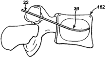
In appeasing the osseous surgery process, in transmitting sleeve pipe 36 partially retracted guide pipes outside 22 or under the situation about removing from outer guide pipe 22 fully, the position is transmitted in the expectation that outer guide pipe 22 is positioned in the bone.For example, in the vertebroplasty operation, outer guide pipe 22 is incorporated into vertebrae 180, preferably at the base of a fruit 182 places.In this regard, vertebrae 180 comprises the vertebra main body 184 of the vertebra wall 186 that limits enclosure body material (spongy bone, blood, bone marrow and other soft tissue) 188.The base of a fruit 182 extends and surrounding ridge vertebral foramen 190 from vertebra main body 184.Particularly, the base of a fruit 182 is attached to the wall that vertebra main body 184 and they comprise vertebra 180 together and form vertebral foramen 190 at the rear portion.As a reference, system 150 is suitable near various bony site in the bone.Therefore, though diagram vertebrae 180 should be appreciated that other bony site can be by system 150 near (that is, femur, long bone, rib, rumpbone etc.).
Transmit position 192 in case form the expectation that outer guide pipe 22 or its be positioned in the bone, transmit sleeve pipe 36 slidably insertions/distal advancement arrive in the outer guide pipe 22.As totally illustrating among Fig. 6 A, the distal portion 82 of transmitting sleeve pipe 36 is equilibrated at distal tip 28 places of outer guide pipe 22.The rough alignment of first degree of depth mark 110a and lever 30 visually provides the distal tip 28 localized affirmations of distal portion 82 with respect to outer guide pipe 22 for user.Before further distal movement, transmit sleeve pipe 36 fully outside in the guide pipe 22, make the deformable segments 88 (Fig. 2 A) of transmitting sleeve pipe 36 be forced to (that is bending) and become straight substantially shape with the shape basically identical of outer guide pipe 22.This pass ties up among Fig. 6 B and clearly show that, thus because the radius of curvature R (Fig. 2 A) that deformable segments 88 is limited under " nature " state greater than the reason of the internal diameter of guide pipe 22, more effectively is applied to deformable segments 88 by guide pipe 22 with power.This preset curvature of " removal " bending section 90 (2A) basically that interacts, force or cause deformable segments 88 to become straight substantially state (to be to be understood that, because the internal diameter of guide pipe 22 is greater than the external diameter that transmits sleeve pipe 36, deformable segments 88 will continue to have slight curvature in guide pipe 22; Therefore, " straight substantially " be meant transmit sleeve pipe 36 for roughly but be not be entirely collinear).Therefore, before interacting, transmit sleeve pipe 36 and bend to straight substantially, non-curved orientation in the guide pipe 22 outside with transmission position 192 (Fig. 6 A).
Transmission casing bit 26 (particularly, transmitting sleeve pipe 36) distal advancement then arrives in the guide pipe 22, shown in Fig. 6 C.Particularly, transmit sleeve pipe 36 and on far-end, handled, make at least a portion deformable segments 88 extend beyond the opening tip 28 of guide pipe 22 and enter transfer part position 192.Not restricted part natural lateral deformation under the situation of leaving guide pipe 22 (from above-mentioned straight substantially shape) of deformable segments 88 now returns to the preset curvature of previously described bending section 90 owing to shape memory characteristic.User can visually confirm to transmit the remote extension length of conduit 36 from guide pipe 22 with respect to the longitudinal register of lever 30 by mark 110b or 110c (mark 110c can see) in Fig. 6 C.In addition, bearing mark 114 is user (point in the patient outside) indication bending section 90 direction in space with respect to the locus of lever 40 in transmitting position 192.
Interrelate with the distal advancement of transmitting sleeve pipe 36, the blunt tip 100 of distal portion 82 is semi-spherical shape (perhaps being non-semi-spherical shape or blunt shape) and the damage that prevents contact tissue/bone thus.In this way, puncture or the situation of the very little risk of the vertebra main body 184 that punctures under, blunt tip 100 can contact and/or survey vertebra wall 186.Therefore, the advantage that blunt tip 100 provides the bone cement that is better than tradition, sharp edges to transmit pin, and, because use the necessity of curved pin, do not need independent line to prevent puncture.
In these cases, in one embodiment, (for example, by controller 154) operations flows body source 152 is delivered to transmission sleeve pipe 36 will correct the material (not shown) via hub 34 then.Enter the rectification material that transmits sleeve pipe 36 and be compelled to pass chamber 86 (Fig. 2 A) towards side opening 84.Shown in Fig. 6 D, correct material and transmit position 192 from transmitting sleeve pipe 36 to enter then from the radial manner distribution/injection of side opening 84 and with cloud form pattern 194.Alternatively or in addition, transmitting position 192 can replace rectification material source 152 (Fig. 6 A) be sucked by using the vacuum source (not shown).
In another embodiment, correct material and be passed to transmission sleeve pipe 36 before being incorporated in the guide pipe 22 will transmitting sleeve pipe 36.In practice, the operator can advance the rectification material and exceed the side opening 84 that transmits sleeve pipe 36, to finish filling transmission sleeve pipe 36 and before inserting guide pipe 22 the unnecessary rectification material of side opening 84 to be wiped then.Transmit sleeve pipe 36 and therefore before transmitting sleeve pipe 36 and guide pipe 22 is connected, be loaded with the rectification material in advance.Insert in the guide pipe 22 in case transmit sleeve pipe 36, correct material and can be used to be delivered to implantation position immediately.This preload step helps reducing will correct material transfer required time in the patient, because it can enter the same substantially time of transmitting the position and finish in that guide pipe 22 is driven.
Importantly, by radially from a side of transmitting sleeve pipe 36 rather than correct material from distal-most end (taking place) injection vertically as using the conventional transmission pin, system 150 (Fig. 6 A) can avoid the rectification material forced and enter crack or other breakage, and this then may cause correcting material and pass and fissuredly do not expect to leak.As example, the crack 196 in Fig. 6 D diagram vertebra main wall 186.Vertebroplasty is for the fissured common solution of this vertebra, the recovery technique of use accepting make it possible to distal portion 82 be positioned at 196 places, crack or " towards " crack 196, distribute in unusual mode to guarantee to correct material near it.Use known transmission pin, this preferred mean of access causes correcting directly 196 injections towards the crack of material.On the contrary, use transmission conduit 36 of the present invention, distal portion 82 also " towards " crack 196, but the rectification material cloud 194 of injection is not directly to force towards the crack 196.As an alternative, correct material cloud 194 and arrive crack 196 indirectly, make that correcting material cloud 194 can not be forced through crack 196 and " leakage " with very little maintenance motive force.But, transmit position 192 and still be filled with rectification material cloud 194 as a whole, to realize the reparation of expectation.
Shown in Fig. 6 D, all transmitting position 192 can be approaching by 36 of sleeve pipes of transmission.In this regard, though guide pipe 22 inserts by correct rear side mean of access, system 150 can be by left side rear side mean of access or right side as shown in Fig. 6 E or the operation of left side rear side mean of access realization vertebroplasty.
In one embodiment, return Fig. 6 C, the rectification material of desired amt transmits by transmitting sleeve pipe 36 fully.In other embodiment in accordance with the principles of the present invention, with the rectification material of first quantity by after transmitting sleeve pipe 36 injections, transmit sleeve pipe 36 and correct material source 152 and separate and remove from guide pipe 22.Correcting material source 152 is connected (for example, fitting 166 and the corresponding fluid port that is provided with lever 30/hub fluid connection) then and operates then with the rectification material with second quantity and be expelled to transmission position 192 by guide pipe 22 with guide pipe 22 fluids.
In a further advantageous embodiment, pipeline 164 rotations of supply rectification material are coupled to and are transmitted casing bit 26.With further reference to Fig. 6 C, in one embodiment, optionally rotary connector 29 is positioned at and transmits between sleeve pipe 26 and the rectification material source 152, rotates relative to one another to allow transmitting sleeve pipe 26 and to correct material source 152.The rotary connector that is suitable for correcting material transfer device is at U.S. Patent application No.11/526, describes in 164, by about the open of rotary connector it being incorporated into this with reference to this patent application.In this embodiment, rotary connector 29 permission doctors rotate and transmit sleeve pipe 26, and thus at the curved end that does not need the transmission sleeve pipe 26 in the rotation implant site under correcting material source and transmitting the situation that sleeve pipe 26 separates or rotate with respect to the transmission sleeve pipe.In a preferred embodiment, rotary connector 29 can be operated with rotation and transmit sleeve pipe 26, preferred about 90 degree, more preferably about 360 degree.
More in general, in appeasing the osseous surgery process, the part that the clinicist of the interior system 150 of operation bone will preset bending section 90 extends into the transmission position 192 that is limited in the bone.In one embodiment, the follow-up rotation of transmitting sleeve pipe 36 is only used once " thrusting " of outer guide pipe 22 and approaching a plurality of planes of transmitting position 192 thus with respect to the locus of transmitting position 192 rotation side openings 84.Therefore, to transmit in the outer guide pipe 22 of sleeve pipe 36 indentations, transmit sleeve pipe 36 by combination with respect to outer guide pipe 22 distal advancement transmission sleeve pipe 36 and by rotating, can be by the single mean of access that transmits the outer guide pipe 22 of sleeve pipe 36 uses near a plurality of planes and a plurality of zone of interested bony site.Therefore, for example, can finish by using system 150 through the pleurocentrum plasty.Fig. 7 A-8B illustrates totally that (Fig. 7 A and 7B be angle internally; Fig. 8 A and 8B are from the left side angle) in each plane/zone of transmitting the vertebra main body 182 that sleeve pipe 36 can be approaching with respect to the rotation of guide pipe 22 and/or advance (keeping under the immobilized situation at guide pipe 22).Notice that in Fig. 7 A-8B, the direction of the bending that transmission sleeve pipe 36 is limited is not necessarily perpendicular to the page, bending may not be very tangible in each view thus.
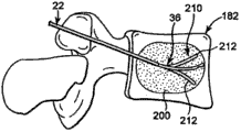
With reference to Fig. 9-10, another method for optimizing that is used to transmit the rectification material is described.In this preferred embodiment, the clinicist produces cavity 210 by the bending section 90 of operation transmission sleeve pipe 36 in the soft tissue material 200 (for example, spongy bone, blood, bone marrow and other soft tissue) in bone transmits the position.Fill with correcting material then in cavity 210.Have been found that when producing the cavity, be delivered to the rectification material that transmits the position and generally flow in cavity 210 rather than the soft material 200.As a result, the clinicist can produce cavity 210 in relatively little desired region, and use is corrected material and mainly filled this zone.
According to a preferred embodiment, can produce the cavity by following mode: combination will transmit the outer guide pipe 22 of sleeve pipe 36 indentations and with respect to outer guide pipe 22 and distal advancement is transmitted conduit 36, complex form moves bending section 90 in the past thus.Reciprocating action makes bending section 90 crushing soft tissues and produce passage 212 in soft tissue.In addition, by will transmit in the outer guide pipe 22 of sleeve pipe 36 indentations and rotation transmit sleeve pipe 36 make bending section 90 with the different orientation distal advancement to transmitting in the position, bending section 90 can produce a plurality of passages 212 in soft tissue 200.In addition, the bending section 90 of transmission sleeve pipe 36 can only partly advance to the transmission position and be removed then to produce than jitty 212 in the implant site of implanting in expectation.
According to another preferred embodiment shown in Figure 10, after bending section 90 has been introduced implant site, transmit sleeve pipe 36 and can rotate or rotate.The rotation or the rotation of transmitting sleeve pipe 36 make bending section 90 transmit position internal rotation or rotation and move through soft tissue 200 rapidly, to produce taper cavity 214 in soft tissue 200 in transmitting the position.By bending section 90 only partly being inserted implant site and rotation transmission sleeve pipe 36, the taper cavity 214 that can produce various sizes.
The various sizes in the soft tissue and the cavity 210 of shape can produce by the combination said method.According to a preferred embodiment, the doctor can will correct material and be incorporated in the implant site when it produces the cavity in implant site.Therefore, can produce simultaneously and filling cavity.
One of ordinary skill in the art is appreciated that, no matter at first produce and then filling cavity still under the situation that does not at first produce the cavity, correct material with the transmission of cloud form pattern, can operate transmission sleeve pipe of the present invention, less sedimentary rectification material transfer is arrived the concrete desired region of intracavity.
In one embodiment, correct material and can in Different Plane, transmit, correct material structure to form, with the soleplate of firm vertebra main body, shown in Figure 1A and 1B at intracavity.In a preferred embodiment, correct material 232a and 232b soleplate 230a and 230b deposition, make that correcting material interferes substantially with soleplate 230a and 230b, and support structure is provided near the vertebra main body.According to a preferred embodiment, operation stays between rectification material deposition 232a and 232b and does not comprise the zone of correcting material substantially.Correcting material therefore can only be deposited in the specific region in chamber.
With reference to Figure 11 C, in a further advantageous embodiment, rectification material deposition 232a and 232b can connect to form rectification material stable column 234 by place the rectification material between rectification material deposition 232a and 232b.In this embodiment, at first produce and correct material deposition 232a and 232b, with the soleplate of firm vertebra main body.Between rectification material deposition 232a and 232b, produce the firm material 234 of correcting then, correct the material deposition and in the vertebra main body, form with connection and correct material structure.By at first firm soleplate, can be firmly because the deformity that pressure fissure causes.Also produce the column type structure then by firm two soleplates between soleplate, the vertebra bulk hardness can significantly improve, and minimizes the problem of the bulk strength of vertebra main body thus.Have been found that with the known method deposition that material is deposited on vertebra main center and correct material (being commonly referred to the operation of kyphoplasty art) or dispersion of materials (being commonly referred to vertebroplasty performs the operation) in whole vertebra main body all can not be reinforced the vertebra main body in heterogeneity.Because cement concentrates on the zone, position, so the soleplate existence is only minimized firm.Also provide the structure that is fixed in then by firm two soleplates, when comparing with known vertebroplasty or the operation of kyphoplasty art, the normal consistency of the more approaching non-fracture vertebra main body of the vertebra bulk hardness of reparation.In another embodiment, if the diagnosis pressure fissure more may occur on the soleplate, then can only need a firm soleplate and only produce one to correct the material deposition near vertebral.In this embodiment, can produce supporting construction, with connect to correct material with the relative vertebral of vertebral of repairing.
With reference to Figure 12, another method for optimizing that is used to transmit the rectification material is described.In this preferred embodiment, transmitting the position is rumpbone 220.In this embodiment, correct material transfer, to repair sclerite or the crack in the rumpbone to rumpbone 220.According to a method for optimizing of the present invention, correct material and be delivered to a plurality of zones in the rumpbone by single access point.Preferably, guide pipe 22 is inserted in the mid portion of rumpbone substantially.As mentioned above, curved pin inserts guide pipe 22 and advances with respect to guide pipe 22.Transmit sleeve pipe 36 and preferably be orientated, make bending section 90 enter first area 221 near rumpbone 220.The rectification material is delivered to the first area 221 of rumpbone 220 then.Correcting material transfer behind first area 221, the doctor then can be with in the bending section 90 part or all of withdrawal guide pipes and then again for transmitting sleeve pipe 36 and bending section 90 orientations.Advance with respect to guide pipe 22 once more because transmit sleeve pipe 36, so bending section 90 enters the second area 222 near rumpbone 220.Correct the second area 222 that material is delivered to rumpbone 220 then.For other zone, can repeat this processing.Though above-mentioned implant site is a rumpbone, correct material transfer to a plurality of zones by using said method to name a person for a particular job by same path, can repair the crack in other bone.
Though illustrated and described specific embodiment here, one of ordinary skill in the art should be appreciated that in not departing from scope of the present invention, plurality of optional and/or be equal to implementation method can replace illustrate with the specific embodiment of describing.This invention is intended to cover any adaptability revision or the variation of specific embodiment discussed here.Therefore, the present invention not only is confined to claim and equivalent thereof.For example, though specifically at the vertebroplasty operation, device, system and method can be applied to equally and will correct material transfer in a plurality of other bones of patient in accordance with the principles of the present invention.
Claims (11)
1. one kind is used for and will corrects the casing bit of material transfer to bone, and it is as a part of correcting the material transfer system, and described rectification material is such as bone cement, and described device comprises:
Transmit sleeve pipe, described transmission sleeve pipe limits:
Open proximal portion;
The deformable segments relative with described close end, described deformable segments ends at distal portion;
Extend from described close end in the chamber;
Wherein, described deformable segments limits a plurality of curved shape that extends longitudinally, and has shape memory characteristic, makes described deformable segments be formed at and longitudinally presents straight substantially form and return to described curved shape naturally when removing power when stressed.
2. device according to claim 1, wherein, described distal portion forms opening.
3. device according to claim 1, wherein, described distal portion forms blind end, and comprises at least one side opening, and the contiguous described distal portion of described side opening forms and is spaced apart at nearside and described distal portion, and described side opening is connected with described chamber fluid.
4. correct the material transfer system in the bone, be used for and will correct the transmission position of material transfer in the bone, described rectification material is such as bone cement, and described system comprises:
Transmit sleeve pipe, described transmission sleeve pipe limits:
Open proximal portion;
The deformable segments relative with described close end, described deformable segments ends at distal portion;
Extend from described close end in the chamber;
Wherein, described deformable segments has shape memory characteristic, and presents the curved shape that extends longitudinally; And
Guide pipe, its internal diameter be greater than the telescopic external diameter of described transmission, and have the open distal end tip;
Wherein, described deformable segments is configured to may be deformed to straight substantially shape, make described transmission sleeve pipe in described guide pipe slidably, and when extending away from described distal tip will correct material transfer by described distal portion in implant site the time, described deformable segments returns to described curved shape naturally; And wherein, described transmission sleeve pipe can smooth sliding in described guide pipe.
5. system according to claim 4, wherein, described guide pipe has level and smooth substantially inside diameter surface.
6. system according to claim 5, wherein, described level and smooth substantially inside diameter surface has the mean-square value of about 0-16.
7. system according to claim 6, wherein, described level and smooth substantially inside diameter surface is coated with layer of teflon.
8. system according to claim 4, wherein, described transmission sleeve pipe has level and smooth substantially external diameter surface.
9. system according to claim 5, wherein, described level and smooth substantially external diameter surface has the mean-square value of about 0-16.
10. system according to claim 4, wherein, described level and smooth substantially external diameter surface is coated with layer of teflon.
11. a rectification material structure that is used for firm vertebra main body comprises:
First corrects the material deposition, approaches the soleplate of vertebra main body, is used to first soleplate of described vertebra main body to provide support;
Second corrects the material deposition, approaches the soleplate of vertebra main body, is used to second soleplate of described vertebra main body to provide support; And
Correct the material post, correct material deposition and described second described first and correct between the material deposition, for described vertebra main body provides support.
Applications Claiming Priority (2)
| Application Number | Priority Date | Filing Date | Title |
|---|---|---|---|
| US11/704,139 US7799035B2 (en) | 2005-11-18 | 2007-02-08 | Device, system and method for delivering a curable material into bone |
| US11/704,139 | 2007-02-08 |
Related Parent Applications (1)
| Application Number | Title | Priority Date | Filing Date |
|---|---|---|---|
| CN2008800114166A Division CN101720207B (en) | 2007-02-08 | 2008-02-08 | Device, system and method for delivering a curable material into bone |
Publications (1)
| Publication Number | Publication Date |
|---|---|
| CN102166131A true CN102166131A (en) | 2011-08-31 |
Family
ID=39386129
Family Applications (2)
| Application Number | Title | Priority Date | Filing Date |
|---|---|---|---|
| CN2011100495937A Pending CN102166131A (en) | 2007-02-08 | 2008-02-08 | Device, system, and method for forming a cavity in and delivering a curable material into bone |
| CN2008800114166A Expired - Fee Related CN101720207B (en) | 2007-02-08 | 2008-02-08 | Device, system and method for delivering a curable material into bone |
Family Applications After (1)
| Application Number | Title | Priority Date | Filing Date |
|---|---|---|---|
| CN2008800114166A Expired - Fee Related CN101720207B (en) | 2007-02-08 | 2008-02-08 | Device, system and method for delivering a curable material into bone |
Country Status (11)
| Country | Link |
|---|---|
| US (3) | US7799035B2 (en) |
| EP (1) | EP2117455A2 (en) |
| JP (1) | JP2010517683A (en) |
| CN (2) | CN102166131A (en) |
| AU (1) | AU2008214200B2 (en) |
| BR (1) | BRPI0807229A2 (en) |
| CA (1) | CA2677644C (en) |
| NZ (1) | NZ579020A (en) |
| RU (1) | RU2009130398A (en) |
| WO (1) | WO2008097659A2 (en) |
| ZA (1) | ZA200905547B (en) |
Cited By (1)
| Publication number | Priority date | Publication date | Assignee | Title |
|---|---|---|---|---|
| WO2014169684A1 (en) * | 2013-04-19 | 2014-10-23 | 南京医科大学第一附属医院 | Operation device for unilateral pedicle vertebroplasty |
Families Citing this family (137)
| Publication number | Priority date | Publication date | Assignee | Title |
|---|---|---|---|---|
| US7258690B2 (en) | 2003-03-28 | 2007-08-21 | Relievant Medsystems, Inc. | Windowed thermal ablation probe |
| US8361067B2 (en) | 2002-09-30 | 2013-01-29 | Relievant Medsystems, Inc. | Methods of therapeutically heating a vertebral body to treat back pain |
| US6907884B2 (en) | 2002-09-30 | 2005-06-21 | Depay Acromed, Inc. | Method of straddling an intraosseous nerve |
| US20060264967A1 (en) | 2003-03-14 | 2006-11-23 | Ferreyro Roque H | Hydraulic device for the injection of bone cement in percutaneous vertebroplasty |
| US8066713B2 (en) | 2003-03-31 | 2011-11-29 | Depuy Spine, Inc. | Remotely-activated vertebroplasty injection device |
| US8415407B2 (en) | 2004-03-21 | 2013-04-09 | Depuy Spine, Inc. | Methods, materials, and apparatus for treating bone and other tissue |
| WO2005030034A2 (en) | 2003-09-26 | 2005-04-07 | Depuy Spine, Inc. | Device for delivering viscous material |
| EP1786343B1 (en) | 2004-07-30 | 2012-05-02 | Depuy Spine, Inc. | Apparatus for treating bone and other tissue |
| US8092464B2 (en) * | 2005-04-30 | 2012-01-10 | Warsaw Orthopedic, Inc. | Syringe devices and methods useful for delivering osteogenic material |
| US9381024B2 (en) | 2005-07-31 | 2016-07-05 | DePuy Synthes Products, Inc. | Marked tools |
| US9918767B2 (en) | 2005-08-01 | 2018-03-20 | DePuy Synthes Products, Inc. | Temperature control system |
| US8366773B2 (en) | 2005-08-16 | 2013-02-05 | Benvenue Medical, Inc. | Apparatus and method for treating bone |
| EP1928520B1 (en) * | 2005-09-07 | 2011-11-09 | Thomas Steffen | Device for injecting high viscosity material |
| DE102005053819A1 (en) * | 2005-11-11 | 2007-05-16 | Khd Humboldt Wedag Gmbh | Rotary kiln burner |
| US7799035B2 (en) * | 2005-11-18 | 2010-09-21 | Carefusion 2200, Inc. | Device, system and method for delivering a curable material into bone |
| US8690884B2 (en) * | 2005-11-18 | 2014-04-08 | Carefusion 2200, Inc. | Multistate-curvature device and method for delivering a curable material into bone |
| US8360629B2 (en) | 2005-11-22 | 2013-01-29 | Depuy Spine, Inc. | Mixing apparatus having central and planetary mixing elements |
| US7922690B2 (en) * | 2006-02-22 | 2011-04-12 | Michael Plishka | Curable material delivery device |
| US8361032B2 (en) * | 2006-02-22 | 2013-01-29 | Carefusion 2200 Inc. | Curable material delivery device with a rotatable supply section |
| US8147500B2 (en) * | 2006-04-20 | 2012-04-03 | Depuy Spine, Inc. | Instrumentation kit for delivering viscous bone filler material |
| US20070260258A1 (en) * | 2006-05-05 | 2007-11-08 | Robert Sommerich | Access and delivery needle for percutaneous vertebroplasty |
| AU2007297097A1 (en) | 2006-09-14 | 2008-03-20 | Depuy Spine, Inc. | Bone cement and methods of use thereof |
| AU2007311451A1 (en) | 2006-10-19 | 2008-04-24 | Depuy Spine, Inc. | Fluid delivery system |
| US20080183192A1 (en) * | 2007-01-26 | 2008-07-31 | Laurimed Llc | Contralateral insertion method to treat herniation with device using visualization components |
| EP2020955A4 (en) * | 2007-05-10 | 2011-07-06 | Depuy Spine Inc | Improved access delivery needle for percutaneous vertebroplasty |
| SG183726A1 (en) | 2007-08-14 | 2012-09-27 | Hutchinson Fred Cancer Res | Needle array assembly and method for delivering therapeutic agents |
| US20090088789A1 (en) * | 2007-09-28 | 2009-04-02 | O'neil Michael J | Balloon With Shape Control For Spinal Procedures |
| US20090131867A1 (en) | 2007-11-16 | 2009-05-21 | Liu Y King | Steerable vertebroplasty system with cavity creation element |
| WO2011066465A1 (en) * | 2009-11-25 | 2011-06-03 | Osseon Therapeutics, Inc. | Steerable and curvable vertebroplasty system with clog-resistant exit ports |
| US9510885B2 (en) | 2007-11-16 | 2016-12-06 | Osseon Llc | Steerable and curvable cavity creation system |
| US8540720B2 (en) * | 2007-12-06 | 2013-09-24 | Javier Garcia-Bengochea | System, instrumentation and method for spinal fixation using minimally invasive surgical techniques |
| US8282648B2 (en) | 2007-12-19 | 2012-10-09 | Cook Medical Technologies Llc | Bone cement needle |
| US8088163B1 (en) | 2008-02-06 | 2012-01-03 | Kleiner Jeffrey B | Tools and methods for spinal fusion |
| US20090209853A1 (en) * | 2008-02-19 | 2009-08-20 | Parihar Shailendra K | Biopsy site marker applier |
| FR2929099B1 (en) * | 2008-03-28 | 2011-05-06 | Jean Charles Persat | DEVICE FOR THE INJECTION IN THE ORGANISM OF A VISCOUS FLUID |
| AU2009231645A1 (en) * | 2008-04-02 | 2009-10-08 | Laurimed, Llc | Methods and devices for delivering injections |
| US8100859B2 (en) * | 2008-06-24 | 2012-01-24 | Cook Medical Technologies Llc | Bent obturator |
| US8277506B2 (en) * | 2008-06-24 | 2012-10-02 | Carefusion 2200, Inc. | Method and structure for stabilizing a vertebral body |
| WO2010006436A1 (en) * | 2008-07-15 | 2010-01-21 | Altavance Ltd. | Bone cement injection device |
| WO2013119258A1 (en) * | 2012-02-10 | 2013-08-15 | Dolor Technologies, L.L.C. | Systems and apparatus for facilitating intranasal treatment of a patient |
| US10028753B2 (en) | 2008-09-26 | 2018-07-24 | Relievant Medsystems, Inc. | Spine treatment kits |
| EP2339972B1 (en) | 2008-09-26 | 2018-04-11 | Relievant Medsystems, Inc. | Systems for navigating an instrument through bone |
| USD853560S1 (en) | 2008-10-09 | 2019-07-09 | Nuvasive, Inc. | Spinal implant insertion device |
| US8366748B2 (en) | 2008-12-05 | 2013-02-05 | Kleiner Jeffrey | Apparatus and method of spinal implant and fusion |
| USD656610S1 (en) | 2009-02-06 | 2012-03-27 | Kleiner Jeffrey B | Spinal distraction instrument |
| US9247943B1 (en) | 2009-02-06 | 2016-02-02 | Kleiner Intellectual Property, Llc | Devices and methods for preparing an intervertebral workspace |
| ES2430913T3 (en) * | 2009-04-09 | 2013-11-22 | Synthes Gmbh | Minimally invasive spine stabilization and augmentation system |
| US20100298832A1 (en) | 2009-05-20 | 2010-11-25 | Osseon Therapeutics, Inc. | Steerable curvable vertebroplasty drill |
| US9241720B2 (en) * | 2009-07-10 | 2016-01-26 | Peter Forsell | Hip joint instrument and method |
| USD723682S1 (en) | 2013-05-03 | 2015-03-03 | Spinal Surgical Strategies, Llc | Bone graft delivery tool |
| US8906028B2 (en) | 2009-09-18 | 2014-12-09 | Spinal Surgical Strategies, Llc | Bone graft delivery device and method of using the same |
| US10245159B1 (en) | 2009-09-18 | 2019-04-02 | Spinal Surgical Strategies, Llc | Bone graft delivery system and method for using same |
| US10973656B2 (en) | 2009-09-18 | 2021-04-13 | Spinal Surgical Strategies, Inc. | Bone graft delivery system and method for using same |
| US9629729B2 (en) | 2009-09-18 | 2017-04-25 | Spinal Surgical Strategies, Llc | Biological delivery system with adaptable fusion cage interface |
| US20170238984A1 (en) | 2009-09-18 | 2017-08-24 | Spinal Surgical Strategies, Llc | Bone graft delivery device with positioning handle |
| US9186193B2 (en) | 2009-09-18 | 2015-11-17 | Spinal Surgical Strategies, Llc | Fusion cage with combined biological delivery system |
| USD750249S1 (en) | 2014-10-20 | 2016-02-23 | Spinal Surgical Strategies, Llc | Expandable fusion cage |
| US9060877B2 (en) | 2009-09-18 | 2015-06-23 | Spinal Surgical Strategies, Llc | Fusion cage with combined biological delivery system |
| US9173694B2 (en) | 2009-09-18 | 2015-11-03 | Spinal Surgical Strategies, Llc | Fusion cage with combined biological delivery system |
| US8685031B2 (en) | 2009-09-18 | 2014-04-01 | Spinal Surgical Strategies, Llc | Bone graft delivery system |
| US20110071391A1 (en) * | 2009-09-24 | 2011-03-24 | Speeg Trevor W V | Biopsy marker delivery device with positioning component |
| US8529465B2 (en) * | 2009-09-24 | 2013-09-10 | Devicor Medical Products, Inc. | Biopsy marker delivery devices and methods |
| JP5538795B2 (en) * | 2009-09-28 | 2014-07-02 | Ntn株式会社 | Remote control type actuator |
| US9095393B2 (en) | 2012-05-30 | 2015-08-04 | Carefusion 2200, Inc. | Method for balloon-aided vertebral augmentation |
| US20110112507A1 (en) * | 2009-11-10 | 2011-05-12 | Carefusion 207, Inc. | Curable material delivery systems and methods |
| US8226657B2 (en) | 2009-11-10 | 2012-07-24 | Carefusion 207, Inc. | Systems and methods for vertebral or other bone structure height restoration and stabilization |
| US8894658B2 (en) | 2009-11-10 | 2014-11-25 | Carefusion 2200, Inc. | Apparatus and method for stylet-guided vertebral augmentation |
| WO2011082499A1 (en) * | 2010-01-11 | 2011-07-14 | Ao Technology Ag | Cannula and kit for injection of bone cement |
| US20110184518A1 (en) * | 2010-01-22 | 2011-07-28 | Warsaw Orthopedic, Inc. | Sacro-iliac joint implant |
| US8221428B2 (en) * | 2010-01-26 | 2012-07-17 | Warsaw Orthopedic, Inc. | Sacro-iliac joint implant system, method and instrument |
| US20110184520A1 (en) * | 2010-01-27 | 2011-07-28 | Warsaw Orthopedic, Inc. | Sacro-iliac joint implant, method and apparatus |
| US8945224B2 (en) * | 2010-03-18 | 2015-02-03 | Warsaw, Orthopedic, Inc. | Sacro-iliac implant system, method and apparatus |
| US20110238181A1 (en) * | 2010-03-29 | 2011-09-29 | Warsaw Orthopedic, Inc., A Indiana Corporation | Sacro-iliac joint implant system and method |
| US9125671B2 (en) | 2010-04-29 | 2015-09-08 | Dfine, Inc. | System for use in treatment of vertebral fractures |
| US8685052B2 (en) | 2010-06-30 | 2014-04-01 | Laurimed, Llc | Devices and methods for cutting tissue |
| ES2545816T3 (en) | 2010-06-30 | 2015-09-16 | Laurimed, Llc | Tissue cutting and evacuation devices |
| AU2014215982B2 (en) * | 2010-06-30 | 2016-10-20 | Myromed, Llc | Devices and methods for cutting and evacuating tissue |
| US9144501B1 (en) | 2010-07-16 | 2015-09-29 | Nuvasive, Inc. | Fracture reduction device and methods |
| JP6062857B2 (en) | 2010-09-20 | 2017-01-18 | クレイナー、ジェフリーKLEINER,Jeffrey | Fusion cage with combined biological delivery system |
| US8771276B2 (en) | 2010-12-01 | 2014-07-08 | Carefusion 2200, Inc. | Systems and methods for forming a cavity in, and delivering curable material into, bone |
| US9039765B2 (en) | 2011-01-21 | 2015-05-26 | Warsaw Orhtopedic, Inc. | Implant system and method for stabilization of a sacro-iliac joint |
| US9060878B2 (en) | 2011-03-28 | 2015-06-23 | Ray G. Oktavec | Percutaneous biologic delivery system |
| EP2699181B1 (en) | 2011-04-19 | 2015-08-05 | AO Technology AG | Cannula and kit for evaluation and preparation of bone tissue |
| WO2012170805A2 (en) * | 2011-06-09 | 2012-12-13 | Knee Creations, Llc | Instruments and devices for subchondral joint repair |
| US8814873B2 (en) | 2011-06-24 | 2014-08-26 | Benvenue Medical, Inc. | Devices and methods for treating bone tissue |
| US20130012951A1 (en) * | 2011-07-08 | 2013-01-10 | Carefusion 207, Inc. | Systems and methods for treating a spine through a single vertebral body insertion point |
| US9119639B2 (en) | 2011-08-09 | 2015-09-01 | DePuy Synthes Products, Inc. | Articulated cavity creator |
| US20130072941A1 (en) * | 2011-09-16 | 2013-03-21 | Francisca Tan-Malecki | Cement Injector and Cement Injector Connectors, and Bone Cement Injector Assembly |
| CN104023760A (en) | 2011-10-28 | 2014-09-03 | 普莱萨格生命科学公司 | Methods for drug delivery |
| US10390877B2 (en) | 2011-12-30 | 2019-08-27 | Relievant Medsystems, Inc. | Systems and methods for treating back pain |
| US9770289B2 (en) | 2012-02-10 | 2017-09-26 | Myromed, Llc | Vacuum powered rotary devices and methods |
| CN102670288B (en) * | 2012-06-05 | 2013-11-27 | 南安新领医疗技术开发有限公司 | Full vertebral body multiple-point bone cement injection needle |
| CN102784434B (en) * | 2012-08-31 | 2013-12-04 | 宁波华科润生物科技有限公司 | Bone filler conveying sleeve |
| EP2892458B1 (en) * | 2012-09-07 | 2019-08-14 | Zimmer Knee Creations, Inc. | Instruments for controlled delivery of injectable materials into bone |
| US10588691B2 (en) | 2012-09-12 | 2020-03-17 | Relievant Medsystems, Inc. | Radiofrequency ablation of tissue within a vertebral body |
| EP2914186B1 (en) | 2012-11-05 | 2019-03-13 | Relievant Medsystems, Inc. | Systems for creating curved paths through bone and modulating nerves within the bone |
| US9439693B2 (en) | 2013-02-01 | 2016-09-13 | DePuy Synthes Products, Inc. | Steerable needle assembly for use in vertebral body augmentation |
| US9717551B2 (en) | 2013-02-21 | 2017-08-01 | Carefusion 2200, Inc. | Intravertebral tissue ablation device and method |
| WO2014134624A1 (en) * | 2013-03-01 | 2014-09-04 | The Arizona Board Of Regents On Behalf Of The University Of Arizona | Modified veress needle for tension pneumothorax decompression |
| US10085783B2 (en) | 2013-03-14 | 2018-10-02 | Izi Medical Products, Llc | Devices and methods for treating bone tissue |
| US20140276591A1 (en) * | 2013-03-14 | 2014-09-18 | Mi4Spine, Llc | Percutaneous intervertebral annular regeneration |
| US9724151B2 (en) | 2013-08-08 | 2017-08-08 | Relievant Medsystems, Inc. | Modulating nerves within bone using bone fasteners |
| US9808237B2 (en) * | 2013-09-26 | 2017-11-07 | Depuy Mitek, Llc | Methods and devices for passing sutures around anatomical structures |
| WO2015053987A1 (en) | 2013-10-09 | 2015-04-16 | Carefusion 2200, Inc. | Systems for balloon-aided vertebral augmentation |
| CA2927436C (en) | 2013-10-15 | 2022-04-26 | Stryker Corporation | Device for creating a void space in living tissue, the device including a handle with a control knob that can be set regardless of the orientation of the handle |
| US9351739B2 (en) | 2013-12-31 | 2016-05-31 | Amendia, Inc. | Tunneling device |
| US8815099B1 (en) | 2014-01-21 | 2014-08-26 | Laurimed, Llc | Devices and methods for filtering and/or collecting tissue |
| US9393061B2 (en) | 2014-03-17 | 2016-07-19 | Stryker Corporation | Method for balloon-assisted augmentation and fusion of adjacent vertebral bodies |
| EP3142541A4 (en) | 2014-05-13 | 2017-04-26 | Vycor Medical, Inc. | Guidance system mounts for surgical introducers |
| US10350387B2 (en) * | 2014-06-02 | 2019-07-16 | Medtronic, Inc. | Implant tool for substernal or pericardial access |
| US9730707B2 (en) | 2014-08-20 | 2017-08-15 | Kyphon SÀRL | Surgical instrument with graduated markings correlating to angulation |
| US20160310194A1 (en) * | 2015-04-21 | 2016-10-27 | Arthrex, Inc. | Surgical assembly and method for repairing depression fractures |
| USD797290S1 (en) | 2015-10-19 | 2017-09-12 | Spinal Surgical Strategies, Llc | Bone graft delivery tool |
| WO2017124217A1 (en) * | 2016-01-18 | 2017-07-27 | Covidien Lp | Endoscopic surgical clip applier |
| US11364062B2 (en) | 2016-08-18 | 2022-06-21 | Spinal Elements, Inc. | Material delivery surgical device |
| CN106691571A (en) * | 2016-08-29 | 2017-05-24 | 宁波华科润生物科技有限公司 | Transport cannula for skeleton filler |
| WO2018081632A1 (en) | 2016-10-27 | 2018-05-03 | C.R. Bard, Inc. | Intraosseous access device |
| US10478241B2 (en) | 2016-10-27 | 2019-11-19 | Merit Medical Systems, Inc. | Articulating osteotome with cement delivery channel |
| US10080671B2 (en) * | 2016-11-01 | 2018-09-25 | Warsaw Orhtopedic, Inc. | Trial and method for use thereof |
| US11033665B2 (en) | 2016-11-04 | 2021-06-15 | The Arizona Board Of Regents On Behalf Of The University Of Arizona | Modified veress needle assembly for tension pneumothorax decompression |
| US10543016B2 (en) | 2016-11-07 | 2020-01-28 | Vycor Medical, Inc. | Surgical introducer with guidance system receptacle |
| US10376258B2 (en) * | 2016-11-07 | 2019-08-13 | Vycor Medical, Inc. | Surgical introducer with guidance system receptacle |
| CA3041114A1 (en) | 2016-11-28 | 2018-05-31 | Dfine, Inc. | Tumor ablation devices and related methods |
| WO2018107036A1 (en) | 2016-12-09 | 2018-06-14 | Dfine, Inc. | Medical devices for treating hard tissues and related methods |
| EP3565486B1 (en) | 2017-01-06 | 2021-11-10 | Dfine, Inc. | Osteotome with a distal portion for simultaneous advancement and articulation |
| EP3357459A1 (en) | 2017-02-03 | 2018-08-08 | Spinal Surgical Strategies, LLC | Bone graft delivery device with positioning handle |
| US20200038646A1 (en) * | 2017-03-14 | 2020-02-06 | Spinal Generations, Llc | Fluid delivery device and bone screw |
| WO2019098396A1 (en) * | 2017-11-14 | 2019-05-23 | 주식회사 엔도비전 | Device for injecting hemostatic bone wax into body |
| WO2019227151A1 (en) * | 2018-05-29 | 2019-12-05 | Greening Investments Pty Ltd | Needle for harvesting human eggs |
| US11510723B2 (en) | 2018-11-08 | 2022-11-29 | Dfine, Inc. | Tumor ablation device and related systems and methods |
| EP3958752A2 (en) | 2019-04-24 | 2022-03-02 | Stryker Corporation | Systems for off-axis augmentation of a vertebral body |
| WO2021050767A1 (en) | 2019-09-12 | 2021-03-18 | Relievant Medsystems, Inc. | Systems and methods for tissue modulation |
| EP4031040A4 (en) | 2019-09-18 | 2023-11-15 | Merit Medical Systems, Inc. | Osteotome with inflatable portion and multiwire articulation |
| CN112568962A (en) | 2019-09-27 | 2021-03-30 | 巴德阿克塞斯系统股份有限公司 | Stepped needle for an intraosseous access device |
| US12082876B1 (en) | 2020-09-28 | 2024-09-10 | Relievant Medsystems, Inc. | Introducer drill |
| JP2024505335A (en) | 2020-12-22 | 2024-02-06 | リリーバント メドシステムズ、インコーポレイテッド | Prediction of spinal neuromodulation candidates |
| US20230019406A1 (en) * | 2021-07-19 | 2023-01-19 | Warsaw Orthopedic, Inc. | Bone material dispensing system and methods of use |
Citations (3)
| Publication number | Priority date | Publication date | Assignee | Title |
|---|---|---|---|---|
| WO1999008616A1 (en) * | 1997-08-13 | 1999-02-25 | Kyphon Inc. | Systems and methods for injecting flowable materials into bones |
| CN2606571Y (en) * | 2003-04-08 | 2004-03-17 | 吴爱静 | Multifunctional sleeve device |
| WO2005102433A2 (en) * | 2004-04-23 | 2005-11-03 | Leonard Edward Forrest | Device for treatment or evacuation of intervertebral disc |
Family Cites Families (65)
| Publication number | Priority date | Publication date | Assignee | Title |
|---|---|---|---|---|
| US4265231A (en) * | 1979-04-30 | 1981-05-05 | Scheller Jr Arnold D | Curved drill attachment for bone drilling uses |
| DE3327585A1 (en) * | 1982-08-06 | 1984-02-09 | John Martin Oxford Evans | SURGICAL INSTRUMENT FOR EPIDURAL AND SPINAL ANESTHESIA |
| EP0346469A4 (en) * | 1987-11-16 | 1990-07-03 | Univ Druzhby Narodov | Trocar. |
| US5295980A (en) * | 1989-10-30 | 1994-03-22 | Ersek Robert A | Multi-use cannula system |
| US6248110B1 (en) * | 1994-01-26 | 2001-06-19 | Kyphon, Inc. | Systems and methods for treating fractured or diseased bone using expandable bodies |
| ATE361028T1 (en) * | 1994-01-26 | 2007-05-15 | Kyphon Inc | IMPROVED INFLATABLE DEVICE FOR USE IN SURGICAL METHODS OF FIXATION OF BONE |
| US6241734B1 (en) * | 1998-08-14 | 2001-06-05 | Kyphon, Inc. | Systems and methods for placing materials into bone |
| WO1995020345A1 (en) * | 1994-01-28 | 1995-08-03 | Ep Technologies, Inc. | Minimizing blood contact in cardiac tissue measurements |
| US5601561A (en) * | 1995-01-17 | 1997-02-11 | W. L. Gore & Associates, Inc. | Guided bone rasp |
| US5609629A (en) * | 1995-06-07 | 1997-03-11 | Med Institute, Inc. | Coated implantable medical device |
| US5851209A (en) * | 1996-01-16 | 1998-12-22 | Hospital For Joint Diseases | Bone cerclage tool |
| US5741261A (en) * | 1996-06-25 | 1998-04-21 | Sdgi Holdings, Inc. | Minimally invasive spinal surgical methods and instruments |
| DE19637025A1 (en) | 1996-09-12 | 1998-03-19 | Stephan Herrmann | Pre-evaporating and premixing burner for liquid fuels |
| AU4996097A (en) | 1996-10-23 | 1998-05-15 | Oratec Interventions, Inc. | Method and apparatus for treating intervertebral discs |
| US5843103A (en) * | 1997-03-06 | 1998-12-01 | Scimed Life Systems, Inc. | Shaped wire rotational atherectomy device |
| US5972015A (en) * | 1997-08-15 | 1999-10-26 | Kyphon Inc. | Expandable, asymetric structures for deployment in interior body regions |
| WO1998056301A1 (en) * | 1997-06-09 | 1998-12-17 | Kyphon Inc. | Systems for treating fractured or diseased bone using expandable bodies |
| US5928239A (en) * | 1998-03-16 | 1999-07-27 | University Of Washington | Percutaneous surgical cavitation device and method |
| AU3203599A (en) * | 1998-04-01 | 1999-10-18 | Parallax Medical, Inc. | Pressure applicator for hard tissue implant placement |
| US7572263B2 (en) * | 1998-04-01 | 2009-08-11 | Arthrocare Corporation | High pressure applicator |
| US6440138B1 (en) * | 1998-04-06 | 2002-08-27 | Kyphon Inc. | Structures and methods for creating cavities in interior body regions |
| US6296639B1 (en) * | 1999-02-12 | 2001-10-02 | Novacept | Apparatuses and methods for interstitial tissue removal |
| EP1054703B1 (en) * | 1998-12-09 | 2004-09-15 | Cook Incorporated | Hollow, curved, superelastic medical needle |
| IL130307A0 (en) * | 1999-06-04 | 2000-06-01 | Influence Med Tech Ltd | Bone suturing device |
| US6478793B1 (en) * | 1999-06-11 | 2002-11-12 | Sherwood Services Ag | Ablation treatment of bone metastases |
| ES2164548B1 (en) * | 1999-08-05 | 2003-03-01 | Probitas Pharma Sa | DEVICE FOR DOSAGE OF FRAGUABLE MASS FOR VERTEBROPLASTIA AND OTHER SIMILAR OSEOS TREATMENTS. |
| US6783515B1 (en) * | 1999-09-30 | 2004-08-31 | Arthrocare Corporation | High pressure delivery system |
| US6383188B2 (en) * | 2000-02-15 | 2002-05-07 | The Spineology Group Llc | Expandable reamer |
| US6790210B1 (en) * | 2000-02-16 | 2004-09-14 | Trans1, Inc. | Methods and apparatus for forming curved axial bores through spinal vertebrae |
| US6899716B2 (en) * | 2000-02-16 | 2005-05-31 | Trans1, Inc. | Method and apparatus for spinal augmentation |
| US6575979B1 (en) * | 2000-02-16 | 2003-06-10 | Axiamed, Inc. | Method and apparatus for providing posterior or anterior trans-sacral access to spinal vertebrae |
| US6358251B1 (en) * | 2000-03-21 | 2002-03-19 | University Of Washington | Method and apparatus for forming a cavity in soft tissue or bone |
| FR2808208B1 (en) * | 2000-04-27 | 2002-06-28 | Optimex 2000 Ltd | CANNULA SET FOR HUMAN BODY INJECTIONS |
| WO2001093787A2 (en) * | 2000-06-08 | 2001-12-13 | Cook Incorporated | High pressure injection syringe |
| US7144414B2 (en) * | 2000-06-27 | 2006-12-05 | Smith & Nephew, Inc. | Surgical procedures and instruments |
| WO2002000143A1 (en) * | 2000-06-27 | 2002-01-03 | Kyphon Inc. | Systems and methods for injecting flowable materials into bones |
| US7025771B2 (en) * | 2000-06-30 | 2006-04-11 | Spineology, Inc. | Tool to direct bone replacement material |
| ATE415915T1 (en) * | 2000-07-14 | 2008-12-15 | Kyphon Sarl | DEVICES FOR TREATING VERTEBRATE BODY |
| US7114501B2 (en) * | 2000-08-14 | 2006-10-03 | Spine Wave, Inc. | Transverse cavity device and method |
| US6679886B2 (en) * | 2000-09-01 | 2004-01-20 | Synthes (Usa) | Tools and methods for creating cavities in bone |
| US7008433B2 (en) * | 2001-02-15 | 2006-03-07 | Depuy Acromed, Inc. | Vertebroplasty injection device |
| US6613018B2 (en) * | 2001-02-20 | 2003-09-02 | Vita Licensing, Inc. | System and kit for delivery of restorative materials |
| US7087040B2 (en) * | 2001-02-28 | 2006-08-08 | Rex Medical, L.P. | Apparatus for delivering ablation fluid to treat lesions |
| US6575978B2 (en) * | 2001-04-05 | 2003-06-10 | Spineology, Inc. | Circumferential resecting reamer tool |
| US6746451B2 (en) * | 2001-06-01 | 2004-06-08 | Lance M. Middleton | Tissue cavitation device and method |
| US6814734B2 (en) * | 2001-06-18 | 2004-11-09 | Sdgi Holdings, Inc, | Surgical instrumentation and method for forming a passage in bone having an enlarged cross-sectional portion |
| US6793660B2 (en) * | 2001-08-20 | 2004-09-21 | Synthes (U.S.A.) | Threaded syringe for delivery of a bone substitute material |
| WO2003037166A2 (en) * | 2001-11-01 | 2003-05-08 | Boyd Lawrence M | Devices and methods for the restoration of a spinal disc |
| US7066942B2 (en) * | 2002-10-03 | 2006-06-27 | Wright Medical Technology, Inc. | Bendable needle for delivering bone graft material and method of use |
| US6875219B2 (en) * | 2003-02-14 | 2005-04-05 | Yves P. Arramon | Bone access system |
| US20060264967A1 (en) * | 2003-03-14 | 2006-11-23 | Ferreyro Roque H | Hydraulic device for the injection of bone cement in percutaneous vertebroplasty |
| US7473267B2 (en) * | 2003-04-25 | 2009-01-06 | Warsaw Orthopedic, Inc. | System and method for minimally invasive posterior fixation |
| MXPA06002541A (en) * | 2003-09-03 | 2006-06-20 | Kyphon Inc | Devices for creating voids in interior body regions and related methods. |
| US7632294B2 (en) * | 2003-09-29 | 2009-12-15 | Promethean Surgical Devices, Llc | Devices and methods for spine repair |
| US20050113843A1 (en) * | 2003-11-25 | 2005-05-26 | Arramon Yves P. | Remotely actuated system for bone cement delivery |
| US20060064101A1 (en) * | 2004-02-12 | 2006-03-23 | Arthrocare Corporation | Bone access system |
| WO2006004887A2 (en) * | 2004-06-29 | 2006-01-12 | Spine Wave, Inc. | Methods for treating defects and injuries of an intervertebral disc |
| US20060195091A1 (en) * | 2005-02-15 | 2006-08-31 | Mcgraw J K | Percutaneous spinal stabilization device and method |
| JP2006263184A (en) * | 2005-03-24 | 2006-10-05 | Gc Corp | Bone cement injection and filling method and leakage prevention bag for injecting and filling bone cement |
| US7972312B2 (en) * | 2005-04-11 | 2011-07-05 | Koopman Robert A | Compac syringe |
| JP2006288864A (en) * | 2005-04-13 | 2006-10-26 | Padoru:Kk | Bone fixture for surgical operation |
| FR2885512B1 (en) * | 2005-05-10 | 2007-08-10 | Biocoral Inc | SYRINGE FOR BIO-MATERIAL |
| US7713273B2 (en) * | 2005-11-18 | 2010-05-11 | Carefusion 2200, Inc. | Device, system and method for delivering a curable material into bone |
| US7799035B2 (en) * | 2005-11-18 | 2010-09-21 | Carefusion 2200, Inc. | Device, system and method for delivering a curable material into bone |
| US7850651B2 (en) * | 2008-09-15 | 2010-12-14 | Biomet Biologics, Llc | Bone marrow aspiration needle |
-
2007
- 2007-02-08 US US11/704,139 patent/US7799035B2/en active Active
-
2008
- 2008-02-08 EP EP08725388A patent/EP2117455A2/en not_active Withdrawn
- 2008-02-08 BR BRPI0807229-9A2A patent/BRPI0807229A2/en not_active IP Right Cessation
- 2008-02-08 RU RU2009130398/14A patent/RU2009130398A/en not_active Application Discontinuation
- 2008-02-08 AU AU2008214200A patent/AU2008214200B2/en not_active Expired - Fee Related
- 2008-02-08 CA CA2677644A patent/CA2677644C/en not_active Expired - Fee Related
- 2008-02-08 WO PCT/US2008/001747 patent/WO2008097659A2/en active Application Filing
- 2008-02-08 CN CN2011100495937A patent/CN102166131A/en active Pending
- 2008-02-08 CN CN2008800114166A patent/CN101720207B/en not_active Expired - Fee Related
- 2008-02-08 JP JP2009549127A patent/JP2010517683A/en active Pending
- 2008-02-08 NZ NZ579020A patent/NZ579020A/en not_active IP Right Cessation
-
2009
- 2009-08-07 ZA ZA2009/05547A patent/ZA200905547B/en unknown
- 2009-12-08 US US12/633,358 patent/US8529576B2/en active Active
- 2009-12-09 US US12/634,366 patent/US8128633B2/en active Active
Patent Citations (3)
| Publication number | Priority date | Publication date | Assignee | Title |
|---|---|---|---|---|
| WO1999008616A1 (en) * | 1997-08-13 | 1999-02-25 | Kyphon Inc. | Systems and methods for injecting flowable materials into bones |
| CN2606571Y (en) * | 2003-04-08 | 2004-03-17 | 吴爱静 | Multifunctional sleeve device |
| WO2005102433A2 (en) * | 2004-04-23 | 2005-11-03 | Leonard Edward Forrest | Device for treatment or evacuation of intervertebral disc |
Cited By (1)
| Publication number | Priority date | Publication date | Assignee | Title |
|---|---|---|---|---|
| WO2014169684A1 (en) * | 2013-04-19 | 2014-10-23 | 南京医科大学第一附属医院 | Operation device for unilateral pedicle vertebroplasty |
Also Published As
| Publication number | Publication date |
|---|---|
| US20100121336A1 (en) | 2010-05-13 |
| AU2008214200B2 (en) | 2012-07-26 |
| US20100087828A1 (en) | 2010-04-08 |
| US7799035B2 (en) | 2010-09-21 |
| BRPI0807229A2 (en) | 2014-06-03 |
| US20070142842A1 (en) | 2007-06-21 |
| ZA200905547B (en) | 2011-04-28 |
| CA2677644A1 (en) | 2008-08-14 |
| JP2010517683A (en) | 2010-05-27 |
| US8128633B2 (en) | 2012-03-06 |
| WO2008097659A2 (en) | 2008-08-14 |
| EP2117455A2 (en) | 2009-11-18 |
| NZ579020A (en) | 2011-12-22 |
| CN101720207A (en) | 2010-06-02 |
| WO2008097659A3 (en) | 2008-10-16 |
| AU2008214200A1 (en) | 2008-08-14 |
| US8529576B2 (en) | 2013-09-10 |
| CN101720207B (en) | 2011-10-05 |
| CA2677644C (en) | 2012-09-18 |
| RU2009130398A (en) | 2011-03-20 |
Similar Documents
| Publication | Publication Date | Title |
|---|---|---|
| CN101720207B (en) | Device, system and method for delivering a curable material into bone | |
| US20080228192A1 (en) | Cannula | |
| US11166747B2 (en) | Methods of manipulating cancellous bone within a vertebral body | |
| US11344350B2 (en) | Articulating osteotome with cement delivery channel and method of use | |
| US10292716B2 (en) | Devices and methods for vertebrostenting | |
| US8827981B2 (en) | Steerable vertebroplasty system with cavity creation element | |
| EP2762099B1 (en) | Steerable cannula assembly | |
| CN100586388C (en) | Spinal stabilization device | |
| US20100298832A1 (en) | Steerable curvable vertebroplasty drill | |
| US20090149878A1 (en) | Bone treatment systems and methods | |
| CN101287415A (en) | Sequential dilator system | |
| JP2013510647A (en) | Curable material delivery system and method | |
| US20230248392A1 (en) | Devices, systems, and methods of use for delivery of materials in combination with intramedullary devices | |
| US20090005816A1 (en) | Spinal rod, insertion device, and method of using | |
| AU2017204475B2 (en) | Steerable vertebroplasty system with cavity creation element |
Legal Events
| Date | Code | Title | Description |
|---|---|---|---|
| C06 | Publication | ||
| PB01 | Publication | ||
| C10 | Entry into substantive examination | ||
| SE01 | Entry into force of request for substantive examination | ||
| C02 | Deemed withdrawal of patent application after publication (patent law 2001) | ||
| WD01 | Invention patent application deemed withdrawn after publication |
Application publication date: 20110831 |