CN102142732A - Layered runner motor shell of dust collector - Google Patents
Layered runner motor shell of dust collector Download PDFInfo
- Publication number
- CN102142732A CN102142732A CN2010103009743A CN201010300974A CN102142732A CN 102142732 A CN102142732 A CN 102142732A CN 2010103009743 A CN2010103009743 A CN 2010103009743A CN 201010300974 A CN201010300974 A CN 201010300974A CN 102142732 A CN102142732 A CN 102142732A
- Authority
- CN
- China
- Prior art keywords
- shell
- dust catcher
- layering
- casing
- runner
- Prior art date
- Legal status (The legal status is an assumption and is not a legal conclusion. Google has not performed a legal analysis and makes no representation as to the accuracy of the status listed.)
- Pending
Links
Images


Abstract
The invention discloses a layered runner motor shell of a dust collector and belongs to electric mechanical equipment of the dust collector. The layered runner motor shell of the dust collector comprises inner shell bodies, square outer shells, outer shell air inlets and exhaust ports, wherein dust collection motors are respectively arranged in the inner shell bodies; the inner shell bodies are provided with vent holes; the square outer shells are arranged outside the inner shell bodies at certain spatial distance; each outer shell consists of an outer shell body and an outer shell cover; the outer shell air inlets are formed on the top of the corresponding outer shell covers; the exhaust ports are used for exhausting air from the outer shells; transverse clapboards for partly dividing the inside spaces of the outer shell are formed in the outer shells; the vent holes are formed on the peripheral walls of the inner shell bodies at the side that the center lines of the circle centers are passed through below the transverse clapboard so as to form lower clapboard channels and upper clapboard channels; and uplink runners and downlink runners are formed at the parts which are not divided by the transverse clapboards. By the layered runner motor shell adopting the design, the lengths of the runners for exhausting air are increased and the transmission loss of noise is improved, so that the noises generated when the motor shell of the dust collection exhausts the air are reduced.
Description
Technical field
The present invention relates to the electricapparatus equipment of dust catcher, specifically is a kind of layering runner motor casing of dust catcher.
Background technology
Dust catcher is a kind of cleaning and sanitary electric equipment device, is used for removing the dust in ground, carpet, wall, furniture, clothing and various slits.
Profile classification according to dust catcher can be divided into vertical type dust collector, horizontal (pot type) dust catcher and portable dust collector etc.
The dust catcher general structure comprises by the motor of dust collector that imports electric current generation suction, forms suction nozzle, the dust pick up hose of air path system, filter, and the dust collect plant of assembling inhalation (inhalatio).
Motor of dust collector at the generation negative-pressure sucking of inner of dust catcher body setting is placed in the motor box, and generates air and discharge air-flow.
Chinese patent 101084819 discloses a kind of " vacuum cleaner ", electric machine assembly wherein, and it is used for sucking air to above-mentioned body of dust collector, and its pressure is flowed; Motor housing, it includes cavity inner wall and chamber outer wall, and wherein above-mentioned cavity inner wall is configured for holding the motor cavity of above-mentioned electric machine assembly, and above-mentioned chamber outer wall forms along the outer periphery of the above-mentioned cavity inner wall set a distance of both being separated by; Wherein upper panel is also installed on the top of the cavity inner wall of motor housing and chamber outer wall, thereby the bottom surface that forms by above-mentioned upper panel and cavity inner wall, chamber outer wall and motor housing surrounds the space that forms.But it produces the present invention in effective attenuation electric machine assembly and to the motor housing of the noise of external communication, to reduce the noise of vacuum cleaner by adopting.
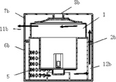
Fig. 1 is the vertical profile structural representation of prior art motor casing, as shown in Figure 1, in the inside of dust catcher body (not shown), dust sucting motor 1 is installed in the inner housing 2a, the top of inner housing 2a is provided with the interior cap 4 that forms inner casing air inlet 3a, and densely covered air vent hole 5 is formed at the bottom.The outside of inner housing 2a also is provided with the shell 13a that keeps the certain space distance with it, shell 13a is made of shell body 6a and casing cover 7a, casing cover 7a center of top on shell body 6a is formed with shell air inlet 8a, the inner casing air inlet 3a place of cap 4a is provided with absorbing silencer 9 on the corresponding inner housing, enters the noise of gas in order to reduction; Be provided with the beam 10 that reduces motor oscillating between the inner bottom part of shell body 6a and inner housing 2a, the sidewall of shell body 6a is formed with the outer up exhaust passage of shell, and through exhaust outlet 11a clean air is discharged to outside the dust catcher body.
Gas communication process in the motor casing of the above-mentioned prior art of brief description.Through the negative pressure pure air behind the inner dedusting of dust catcher body (not shown), filtration, the control of dust, muffler 9 noise reductions after the shell air inlet 8a on the casing cover 6a enter in the shell body 6a, and enter dust sucting motor 1 by the inner casing air inlet 3a of cap 4a in the inner housing, and the gas of discharging via dust sucting motor 1 gas outlet, the air vent hole 5 that gathers by inner housing 2a bottom enters in the shell body 6a, and outer up runner 12a and the exhaust outlet 11a of shell 13a that forms by shell body 6a one side, the air of cleaning is discharged to outside the dust catcher body.
But, above-mentioned prior art have a following deficiency, nearer via the gas that discharge dust sucting motor 1 gas outlet apart from the exhaust outlet 11a of shell body 6a, too short at the air flow channel in shell body 6a, therefore, limited to slackening of noise, noise reduction is not obvious, and use foamed plastics (not shown) to absorb noise merely, can not fully solve the problem that noise reduces.
Summary of the invention
The present invention is exactly in order to solve in the prior art, in the ubiquitous motor casing gas flow too short, utilize the foamed plastics sound-absorbing merely, the unconspicuous problem of noise reduction, and a kind of layering dual channel motor casing of dust catcher is provided.
The present invention realizes by following technical scheme.
A kind of layering runner motor casing of dust catcher, comprise built-in dust sucting motor and be formed with the inner housing of air vent hole, be arranged on the square shell of the outside also interval of inner housing certain space distance, shell is made of shell body and casing cover, be formed on the shell air inlet at casing cover top, and discharge the exhaust outlet of gas from shell, and and being formed with the diaphragm plate that the inner space part is separated in the enclosure, air vent hole is formed on inner housing and crosses on the following perisporium of the diaphragm plate of center of circle center line one side.
She Ji the present invention is owing to be formed with the diaphragm plate that the inner space part is separated in the enclosure like this, thereby formed dividing plate lower floor passage and dividing plate upper strata passage, and the part that is separated by diaphragm plate does not form up runner and descending runner.In addition, air vent hole is formed on inner housing and crosses on the following perisporium of the diaphragm plate of center of circle center line one side, the gas of discharging from inner housing must be detoured after, discharge from the exhaust outlet of shell body again.Therefore, increase the flow channel length that air-flow is discharged, increased the propagation loss of noise, and then reduce the noise that the motor of dust collector shell is discharged gas.
Description of drawings
Fig. 1 is the motor of dust collector shell vertical profile structure and the gas flow path schematic diagram of prior art;
Fig. 2 is a decomposition texture schematic diagram of the present invention;
Fig. 3 is a volume rendering structural representation of the present invention;
Fig. 4 is vertical profile structure of the present invention and gas flow path schematic diagram;
Fig. 5 is the decomposition texture schematic diagram of another embodiment of the present invention;
Fig. 6 is the part-structure schematic diagram of another embodiment of the present invention;
Fig. 7 is the surface structure schematic diagram of another embodiment of the present invention;
Fig. 8 is the vertical profile structure and the gas flow path schematic diagram of another embodiment of the present invention.
The label symbol of major part among the figure:
1. dust sucting motor 2a.2b.2c. inner housing
3a.3b. cap in the inner casing air inlet 4a.4b
5. air vent hole 6a.6b.6c. shell body
7a.7b.7c casing cover 8a.8b.8c shell air inlet
9. muffler 10. beams
11a.11b.11c the up runner of exhaust outlet 12a.12b.12c
13a.13b.13c shell 14a.14b. diaphragm plate
15. inner hull 16. inner casing orifice plates
17. mediastinum orifice plate 18. descending runners
19. beam location notch arrow is represented airflow direction.
Embodiment
The present invention will be described in detail below in conjunction with drawings and Examples.
A kind of layering runner motor casing of dust catcher, comprise built-in dust sucting motor 1 and be formed with the inner housing 2b.2c of air vent hole 5, be arranged on the square shell 13b of the outside also interval of inner housing 2b.2c certain space distance, 13c, shell 13b, 13c is by shell body 6b, 6c and casing cover 7b, 7c constitutes, be formed on casing cover 7b, the shell air inlet 8b at 7c top, 8c, and from shell 13b, 13c discharges the exhaust outlet 11b of gas, 11c, and at shell 13b, be formed with the diaphragm plate 14a that the inner space part is separated in the 13c, 14b, air vent hole 5 is formed on inner housing 2b, 2c crosses the diaphragm plate 14a of center of circle center line one side, on the perisporium below the 14b.
Described dust catcher layering runner motor casing, its diaphragm plate 14a be formed among the inner housing 2b, on the anterior periphery wall.Thereby form dividing plate upper strata passage and dividing plate lower floor passage in the shell 13b.And inner housing 2b rear portion does not possess and forms up runner 12b between the periphery wall (described below) of air vent hole 5 and shell body 6b rear wall.
Described dust catcher layering runner motor casing, its diaphragm plate 14b are formed on the periphery wall of corresponding two middle side parts of circular interior cap (4b) end mouth.Thereby form dividing plate upper strata passage and dividing plate lower floor passage in the shell 13c.And be not formed with the other corresponding both sides of interior cap (4b) of diaphragm plate 14b, then become up runner 12c and descending runner 18 in the shell 13c respectively.
Described dust catcher layering runner motor casing, the exhaust outlet 11b that discharges gas from shell 13b is formed on the leading flank of casing cover 7b.
Described dust catcher layering runner motor casing, the exhaust outlet 11c that discharges gas from shell 13c is formed on the leading flank bottom of shell body 6c.
Described dust catcher layering runner motor casing, its inner housing 2c are integrally formed with shell body 6c inwall respectively by in opposite directions circular-arc inner hull 15 and circular-arc inner casing orifice plate 16 two ends.
Described dust catcher layering runner motor casing, its air vent hole 5 are formed on following the crossing on the center line one side perisporium of the center of circle of inner housing 2b periphery diaphragm plate 14a, or be formed on circular-arc inner hull 15 circular-arc inner casing orifice plate 16 in opposite directions on.
Described dust catcher layering runner motor casing, itself and circular-arc inner hull 15 in opposite directions circular-arc inner casing orifice plate 16 and shell body 6c between be provided with the mediastinum orifice plate 17 that forms up runner 12c.
Described dust catcher layering runner motor casing forms the descending runner 18 that gas is discharged between the shell body 6c leading flank of the exhaust outlet 11c of its circular-arc inner hull 15 and formation discharge gas.
Described dust catcher layering runner motor casing, its up runner 12b, 12c are formed in shell 13b, the 13c of exhaust outlet 11b, 11c respective side.Be between the dorsal part of mediastinum orifice plate 17 and shell 13c; Or be not formed with between the dorsal part of the inner housing 2b of air vent hole 5 and shell 13b.
19 is beam location notchs among the unaccounted figure.
Below with reference to Fig. 4 and specific embodiment, discharge gas communication situation of the present invention is described.
The shell air inlet 8b of negative-pressure air-flow through square casing cover 7b top that dust sucting motor 1 in the dust catcher body (not shown) produces enters dust sucting motor 1, and the pure air of discharging by dust sucting motor 1, air vent hole 5 by inner housing 2b periphery wall diaphragm plate 14a bottom arrives in the shell body 6b, therefore, form lower floor's passage in the shell body 6b under the diaphragm plate 14a, because the obstruct of diaphragm plate 14a above the air vent hole 5, air can not directly upwards be discharged from exhaust outlet 11b from shell body 6b, and must be at lower floor's runner of inner housing 2b below the diaphragm plate 14a and the formation between the shell body 6b, do not separated and the up runner 12b that forms through exhaust outlet 11b respective side by diaphragm plate 14a, go upward to the above upper strata passage that forms of diaphragm plate 14a in the casing cover 7b, and shunting is detoured to the exhaust outlet 11b discharge of casing cover 7b leading flank.
Below with reference to Fig. 8, Fig. 9 and another embodiment, discharge gas communication situation of the present invention is described.
The negative-pressure air-flow that dust sucting motor 1 in the dust catcher body (not shown) produces is through the shell air inlet 8c at square casing cover 7c top, the inner casing air inlet 3b at cap 4b top enters dust sucting motor 1 in circular, and the pure air of discharging by dust sucting motor 1, below diaphragm plate 14b, constitute the circular-arc inner casing orifice plate 16 of inner housing 2c, and and shell body 6c dorsal surface between lower floor's passage of forming of the mediastinum orifice plate that is provided with 17, and entered the up runner 12c that forms between mediastinum orifice plate 17 and the shell body 6c dorsal surface.And owing to constitute the obstruct of the circular-arc inner hull 15 of inner housing 2c, can not discharge by basifacial exhaust outlet 11c through shell body 6c front side by the pure air that dust sucting motor 1 is discharged, can only go upward to the up runner 12c that is not sealed and form by diaphragm plate 14b, rise up into the above upper strata passage that forms of diaphragm plate 14b in the casing cover 7c, and then shunting detours to the descending runner 18 that forms between the circular-arc inner hull 15 of the inner housing 2c that is not sealed by diaphragm plate 14b and the shell body 6c leading flank, and the exhaust outlet 11c that forms from shell body 6c leading flank bottom discharge.
In addition, paste the sound-absorbing sponge in the upper strata passage about diaphragm plate 14a, 14b and the lower floor's passage, (not shown) is used for increasing the absorption of noise, the final purpose that realizes reducing noise.
Claims (10)
1. the layering runner motor casing of a dust catcher, comprise built-in dust sucting motor (1) and be formed with the inner housing (2b) of air vent hole (5), (2c), be arranged on inner housing (2b), (2c) outside and the square shell (13b) of certain space distance at interval, (13c), shell (13b), (13c) by shell body (6b), (6c) and casing cover (7b), (7c) constitute, be formed on casing cover (7b), (7c) the shell air inlet (8b) at top, (8c), and from shell (13b), (13c) exhaust outlet (11b) of discharge gas, (11c), it is characterized in that: shell (13b), be formed with the diaphragm plate (14a) that the inner space part is separated (13c), (14b), air vent hole (5) is formed on inner housing (2b), (2c) diaphragm plate (14a) of mistake center of circle center line one side, (14b) on the Yi Xia perisporium.
2. according to the described dust catcher layering of claim 1 runner motor casing, it is characterized in that: diaphragm plate (14a) is formed in the inner housing (2b), on the anterior periphery wall.
3. according to the described dust catcher layering of claim 1 runner motor casing, it is characterized in that: diaphragm plate (14b) is formed on the periphery wall of corresponding two middle side parts of interior cap (4b) end mouth.
4. according to the described dust catcher layering of claim 1 runner motor casing, it is characterized in that: the exhaust outlet (11b) of discharging gas from shell (13b) is formed on the leading flank of casing cover (7b).
5. according to the described dust catcher layering of claim 1 runner motor casing, it is characterized in that: the leading flank bottom that is formed on shell body (6c) from the exhaust outlet (11c) of shell (13c) discharge gas.
6. according to the described dust catcher layering of claim 1 runner motor casing, it is characterized in that: inner housing (2c) is integrally formed with shell body (6c) inwall respectively by in opposite directions circular-arc inner hull (15) and circular-arc inner casing orifice plate (16) two ends.
7. according to claim 1 or 6 described dust catcher layering runner motor casings, it is characterized in that: air vent hole (5) is formed on following the crossing on the center line one side perisporium of the center of circle of inner housing (2b) periphery diaphragm plate (14a), or be formed on circular-arc inner hull (15) circular-arc inner casing orifice plate (16) in opposite directions on.
8. according to claim 1 or 9 described dust catcher layering runner motor casings, it is characterized in that: and circular-arc inner hull (15) in opposite directions circular-arc inner casing orifice plate (16) and shell body (6c) between be provided with the mediastinum orifice plate (17) that forms up runner (12c).
9. according to claim 1 or 9 described dust catcher layering runner motor casings, it is characterized in that: form the descending runner (18) that gas is discharged between shell body (6c) leading flank of the exhaust outlet (11c) of circular-arc inner hull (15) and formation discharge gas.
10. according to claim 1 or 8 described dust catcher layering runner motor casings, it is characterized in that: up runner (12b), (12c) are formed in the shell (13b), (13c) of exhaust outlet (11b), (11c) respective side.
Priority Applications (1)
| Application Number | Priority Date | Filing Date | Title |
|---|---|---|---|
| CN2010103009743A CN102142732A (en) | 2010-02-01 | 2010-02-01 | Layered runner motor shell of dust collector |
Applications Claiming Priority (1)
| Application Number | Priority Date | Filing Date | Title |
|---|---|---|---|
| CN2010103009743A CN102142732A (en) | 2010-02-01 | 2010-02-01 | Layered runner motor shell of dust collector |
Publications (1)
| Publication Number | Publication Date |
|---|---|
| CN102142732A true CN102142732A (en) | 2011-08-03 |
Family
ID=44410037
Family Applications (1)
| Application Number | Title | Priority Date | Filing Date |
|---|---|---|---|
| CN2010103009743A Pending CN102142732A (en) | 2010-02-01 | 2010-02-01 | Layered runner motor shell of dust collector |
Country Status (1)
| Country | Link |
|---|---|
| CN (1) | CN102142732A (en) |
Cited By (7)
| Publication number | Priority date | Publication date | Assignee | Title |
|---|---|---|---|---|
| CN103381080A (en) * | 2012-05-02 | 2013-11-06 | 乐金电子(天津)电器有限公司 | Low-noise motor box of dust collector |
| WO2015032150A1 (en) * | 2013-09-06 | 2015-03-12 | 江苏美的春花电器股份有限公司 | Dust collector and exhaust air device thereof |
| WO2015032151A1 (en) * | 2013-09-06 | 2015-03-12 | 江苏美的春花电器股份有限公司 | Dust collector and air intake device thereof |
| CN104421223A (en) * | 2013-08-27 | 2015-03-18 | 珍巴多工业股份有限公司 | Electric blower assembly |
| CN104983362A (en) * | 2015-07-30 | 2015-10-21 | 江苏美的清洁电器股份有限公司 | Engine cover structure and dust collector |
| WO2016058434A1 (en) * | 2014-10-13 | 2016-04-21 | 江苏美的清洁电器股份有限公司 | Air duct structure and surface cleaning device having same |
| CN105559688A (en) * | 2014-10-13 | 2016-05-11 | 江苏美的清洁电器股份有限公司 | Air duct structure and surface cleaning device provided with air duct structure |
-
2010
- 2010-02-01 CN CN2010103009743A patent/CN102142732A/en active Pending
Cited By (9)
| Publication number | Priority date | Publication date | Assignee | Title |
|---|---|---|---|---|
| CN103381080A (en) * | 2012-05-02 | 2013-11-06 | 乐金电子(天津)电器有限公司 | Low-noise motor box of dust collector |
| CN104421223A (en) * | 2013-08-27 | 2015-03-18 | 珍巴多工业股份有限公司 | Electric blower assembly |
| CN104421223B (en) * | 2013-08-27 | 2018-05-25 | 珍巴多工业股份有限公司 | Electric blowing machine assembly |
| WO2015032150A1 (en) * | 2013-09-06 | 2015-03-12 | 江苏美的春花电器股份有限公司 | Dust collector and exhaust air device thereof |
| WO2015032151A1 (en) * | 2013-09-06 | 2015-03-12 | 江苏美的春花电器股份有限公司 | Dust collector and air intake device thereof |
| WO2016058434A1 (en) * | 2014-10-13 | 2016-04-21 | 江苏美的清洁电器股份有限公司 | Air duct structure and surface cleaning device having same |
| CN105559688A (en) * | 2014-10-13 | 2016-05-11 | 江苏美的清洁电器股份有限公司 | Air duct structure and surface cleaning device provided with air duct structure |
| CN105559688B (en) * | 2014-10-13 | 2018-03-30 | 江苏美的清洁电器股份有限公司 | Air channel structure and there is its surface cleaning apparatus |
| CN104983362A (en) * | 2015-07-30 | 2015-10-21 | 江苏美的清洁电器股份有限公司 | Engine cover structure and dust collector |
Similar Documents
| Publication | Publication Date | Title |
|---|---|---|
| CN102142732A (en) | Layered runner motor shell of dust collector | |
| CN102025215A (en) | Motor cover for dust collector | |
| KR100809738B1 (en) | Vacuum cleaner | |
| CN211299813U (en) | Air outlet device and cleaning device | |
| CN102018476A (en) | Motor shield structure for dust collector | |
| CN113892871A (en) | Floor cleaning machine | |
| CN102044930A (en) | Motor cover of hovership type dust collector | |
| CN202235155U (en) | Mute dust collector | |
| CN102309284B (en) | Horizontal dust collector | |
| CN102457131A (en) | Vibration-attenuating and noise-reducing structure of motor shell | |
| CN207928276U (en) | Hand held cleaner noise reducing mechanism | |
| CN214231207U (en) | Floor sweeping robot with double air channels | |
| CN116906347A (en) | Fan device of cleaning equipment, maintenance base station and cleaning robot system | |
| JP2009233013A (en) | Vacuum cleaner | |
| JP2002034861A (en) | Vacuum cleaner | |
| CN103381080A (en) | Low-noise motor box of dust collector | |
| CN103479297A (en) | Low-noise motor casing structure with crossed flow channel of vacuum cleaner | |
| CN217659582U (en) | Negative pressure adsorption equipment and robot of sweeping floor | |
| CN217185913U (en) | Noise-reduction air outlet structure of side air outlet type dust collector | |
| CN102309285A (en) | Silent dust collector | |
| CN218247113U (en) | Floor cleaning machine | |
| CN206214017U (en) | The ground brush assemblies and the dust catcher with it of dust catcher | |
| CN101721181A (en) | Motor exhausting and denoising structure of dust catcher | |
| CN219920947U (en) | Pet dust collector | |
| CN202235176U (en) | Horizontal dust collector |
Legal Events
| Date | Code | Title | Description |
|---|---|---|---|
| C06 | Publication | ||
| PB01 | Publication | ||
| C02 | Deemed withdrawal of patent application after publication (patent law 2001) | ||
| WD01 | Invention patent application deemed withdrawn after publication |
Application publication date: 20110803 |