CN102123866B - A method and an apparatus for processing a lenticular printing substrate - Google Patents
A method and an apparatus for processing a lenticular printing substrate Download PDFInfo
- Publication number
- CN102123866B CN102123866B CN200980131795.7A CN200980131795A CN102123866B CN 102123866 B CN102123866 B CN 102123866B CN 200980131795 A CN200980131795 A CN 200980131795A CN 102123866 B CN102123866 B CN 102123866B
- Authority
- CN
- China
- Prior art keywords
- grating
- base plate
- rotating cylinder
- printed base
- printing
- Prior art date
- Legal status (The legal status is an assumption and is not a legal conclusion. Google has not performed a legal analysis and makes no representation as to the accuracy of the status listed.)
- Expired - Fee Related
Links
Images


Classifications
-
- B—PERFORMING OPERATIONS; TRANSPORTING
- B41—PRINTING; LINING MACHINES; TYPEWRITERS; STAMPS
- B41F—PRINTING MACHINES OR PRESSES
- B41F17/00—Printing apparatus or machines of special types or for particular purposes, not otherwise provided for
-
- B—PERFORMING OPERATIONS; TRANSPORTING
- B41—PRINTING; LINING MACHINES; TYPEWRITERS; STAMPS
- B41M—PRINTING, DUPLICATING, MARKING, OR COPYING PROCESSES; COLOUR PRINTING
- B41M3/00—Printing processes to produce particular kinds of printed work, e.g. patterns
-
- B—PERFORMING OPERATIONS; TRANSPORTING
- B41—PRINTING; LINING MACHINES; TYPEWRITERS; STAMPS
- B41M—PRINTING, DUPLICATING, MARKING, OR COPYING PROCESSES; COLOUR PRINTING
- B41M3/00—Printing processes to produce particular kinds of printed work, e.g. patterns
- B41M3/14—Security printing
Abstract
A method for preparing a lenticular guide roll for use in a lenticular printing run is provided. The method comprises providing a printing roll of a printing press and a first piece of lenticular media. The first piece of lenticular printing substrate has a pitch which is substantially identical to a second lenticular printing substrate to be used in the lenticular printing run. The method further comprises attaching the first piece of lenticular printing substrate to the printing roll to allow the maneuvering of the second lenticular printing substrate by the printing roll in the printing press.
Description
Technical field
The invention provides a kind of for being aligned in the simple device of reel paper feeding (web-fed) medium that grating printing and lith process used.Particularly, the present invention allows to make traditional rotating cylinder (roll) of using in conventional or digital printed technology or cylinder (drum) to become the good transformation for the guiding rotating cylinder of the high precision of grating printing.By by the surface conjunction of suitable grating or raster-like (bond) or attach to one or more rollers (roller), can be rapidly and at an easy rate by printing machine or digital printer transformation for the printing of high accuracy grating.
Background technology
Since the forties in 20th century, brought into use grating printing.Particularly, grating printing comprises and divides slivering by visual picture; Make image strip alternation sum configuration image bar below the region of grating lens.The visual effect of grating comprises the obvious 3 dimension degree of depth, and as the staggered image of the function of viewing angle (" upset "), and object is along with obvious " motion " of observer's movement.Have been found that a large amount of use grating printing in advertisement with in promoting.At airport and the large-scale grating indicating characteristic of a large amount of use of shopping plaza.
Grating printing relies on unique optical phenomena of feeling by observer.So grating is printed on misalignment (misalignment) aspect of image with respect to grating lens, has extremely low error permission level, wherein, can see image by grating lens.Grating printing relies on unique optical phenomena of feeling by observer.Various grating printings are conventionally based on multiple images, and they are cut into bar, then staggered with one or more other images.Lens and each image are staggered to be aligned, to light is reflected away or allow light pass, each reflects with slightly different direction, but send with identical direction from the light of all of Given Graph picture.Final result is, eye or the camera of viewing graphic pattern are seen a complete image, but the eyes at different visual angles or camera will be seen different images.So grating is printed on the misalignment aspect of image strip with respect to grating lens, there is extremely low error permission level, by grating lens, can see image.Even if the little skew of image strip or misalignment also may cause changing aforesaid final result, and observer may see the reflection of multiple image strips simultaneously, rather than sees in a continuous manner them.Grating printing conventionally by the feeding of grating printed base plate and while putting into printing machine with high precision work.Little mistake during printing may be brought economical and temporal loss.For realizing high-quality grating printing, grating printed medium and printing equipment should be in all stages of typography, especially during ink transfer printing, keep aiming at, and preferably aim at completely.Common misalignment problem is included in the movement of feeding grating printed base plate during printing operation.Particularly, grating web media (web media) moves between paired rotating cylinder, idle running rotating cylinder and impression rotating cylinder, and some so paired rotating cylinders are generally and use to produce complete high-quality image serially.The misalignment of the little grating printed base plate causing because of reel skew or reel accompany movement may cause the quality degradation of high responsive raster image.Any motion or the distortion of grating web media during printing may cause cost height and irreversible misalignment.
Bravenec is in U.S. Pat 6,276, described in 269 a kind of for guaranteeing the method for aligning of grating reel feeding.In his method, Bravenec has described and has had the guiding rotating cylinder of " being formed on one group of groove circumferentially extending on the outer surface of roller ".Groove is aimed at as the grating lens material (printing occurs on the planar side relative with grating lens) that makes to be fed in printing machine.
Summary of the invention
According to some embodiments of the present invention, provide a kind of method of the manufacture grating guiding rotating cylinder that is used to raster image.Described method comprises provides the printing of printing machine rotating cylinder and first grating medium, and first grating printed base plate has the spacing being substantially equal to the second grating printed base plate using aborning; With first grating printed base plate attached to printing rotating cylinder.Attached permission is handled second grating printed base plate by printing rotating cylinder in printing machine.
Alternatively, described production comprises the production of grating printing operation.
Alternatively, printing rotating cylinder selects the group of freely dally rotating cylinder and impression cylinder formation.
Alternatively, described attached step comprises first grating medium is incorporated into printing rotating cylinder.
Alternatively, described manipulation comprises the position of using the printing rotating cylinder with first attached grating printed base plate to record second grating printed base plate at production period.
Alternatively, printing rotating cylinder be for the production of multiple printing rotating cylinders in one.
Alternatively, printing rotating cylinder is covered by first grating printed base plate at least in part on its circumference.
Alternatively, first grating printed base plate has the groove for aiming at second grating printed base plate of chien shih campaign.
Alternatively, described method further comprises the first and second relative edges of the first grating printed base plate that be shaped, to allow its splicing during attached.
Further alternatively, described method further comprises that the first pattern and the second pattern are opposite each other according to the first waveform pattern-forming first-phase opposite side with according to the second waveform pattern-forming second-phase opposite side.
Further alternatively, the first waveform patterns is square waveform pattern.
According to some embodiments of the present invention, provide a kind of for standard print roller being changed into the external member of grating guiding rotating cylinder of printing machine.Described external member comprises first grating printed base plate and is configured for first grating printed base plate to be fixed on the attached element in standard print roller.Described fixing permission is processed second grating printed base plate with printing machine.
Alternatively, described processing is included on second grating printed base plate and prints.
Alternatively, described fixing use adhesive material is carried out.
Alternatively, printing rotating cylinder selects the group of freely dally rotating cylinder and impression cylinder formation.
Alternatively, the grating of first and second grating printed base plates has at least one substantially the same spacing physical size substantially the same with at least one.
Alternatively, attached element selects the group that free securing member, press element, nail, clip and binding member form.
According to some embodiments of the present invention, provide a kind of method of the guiding rotating cylinder for the preparation of using in grating printing operation.Described method comprises provides roller and a raster-like medium, and a described raster-like medium has the grating-alignment characteristics being substantially equal to the grating printed base plate using in grating printing operation; With a described raster-like medium is attached to printing rotating cylinder, make the grating associated with the raster-like medium-alignment characteristics back of the body towards printing rotating cylinder.
Alternatively, printing rotating cylinder is idle running rotating cylinder.
Alternatively, described attached step realizes by apply adhesive between printing rotating cylinder and a grating medium.
Accompanying drawing explanation
Here, only by way of example, describe some embodiments of the present invention with reference to the accompanying drawings., by concrete at length reference accompanying drawing, should emphasize now, show by way of example details, and the details showing is for the object of the illustrative discussion of embodiments of the invention.In this sense, with reference to the description of accompanying drawing, make those skilled in the art know that how to implement embodiments of the invention.
In accompanying drawing:
Figure 1A and 1B have described according to schematic top view and the side view of the grating printed base plate of some embodiments of the present invention;
Fig. 2 has described according to the schematic diagram of the standard digital printing machine of some embodiments of the present invention, and described standard digital printing machine is used for multiple image adhesion at printable grating medium;
Fig. 3 A has described standard print roller to be changed into the required parts of grating guiding rotating cylinder according to some embodiments of the present invention;
Fig. 3 B is according to the indicative icon of the edge splicing of the grating printed base plate of some embodiments of the present invention;
Fig. 4 A has described the feeding of grating web media to be entered and passed through according to some embodiments of the present invention the grating guiding rotating cylinder using in print steps;
It is schematically close that Fig. 4 B has described to insert according to the grating lens on rotating cylinder in guiding of some embodiments of the present invention and printable medium;
Fig. 5 has described the multiple grating guiding rotating cylinders that use in some embodiments of the invention; With
Fig. 6 has described the flow chart for the production of the method for grating guiding rotating cylinder according to the definition of some embodiments of the present invention.
The specific embodiment
One of some objects of the present invention are that the guiding rotating cylinder using in grating printing and similar typography is provided.Grating guiding rotating cylinder can form by a grating printed base plate is attached to printing machine rotating cylinder, and grating reel structure outwardly, and is aimed at as the grating web media that makes feeding enter printing machine and guiding rotating cylinder top.Grating reel structure is attached to rotating cylinder can be realized by any device, includes, but are not limited to gluing and clamps.Attached can be permanent or temporary transient.Should understand, grating printed base plate is attached to print roller, by by the non-grating of grating printed base plate (" smooth ") side in conjunction with or the whole circumference that attaches to roller realize, so that the grating lens side of attached grating printed base plate will be outwardly, and towards the feeding grating cylinder material through printing machine.The grating printed base plate of selecting for attaching to roller is substantially the same with the grating printed base plate using in grating printing subsequently aspect spacing.
Can use in a similar fashion non-grating printed base plate, wherein grating-the alignment characteristics of this material be attached with from it non-grating printed base plate common printed roller outwardly.Grating-alignment characteristics has permission grating lens interconnected size and the spacing associated with printable grating printed base plate, and therefore can on grating medium, during printing images, maintain the aligning of grating printed base plate.
Unless otherwise definition, all technology used herein and/or scientific and technical terminology have the general meaning that understand, identical of those skilled in the art.Although may use in the practice of embodiments of the invention or test, be similar to or be equal to those methods described herein and material, will describe exemplary method and/or material below.For preventing conflicting, patent specification, comprises definition, will control this.In addition, material, method and be only illustrative for example, be not intended to limit inevitably.
In describing subsequently, will illustrate many details, to thoroughly understand the present invention.But, for those skilled in the art, may, without these details, just can implement the present invention.In other example, without departing from the scope and spirit of the present invention, can use in the present invention alternative materials.The aspect of uniqueness of the present invention is, grating printed base plate is attached to standard press rotating cylinder, outwardly, and the grating web media that feeding is entered in the printing machine that uses guiding rotating cylinder plays guiding to grating lens, and it has nothing to do with material or concrete attached strategy.
For understanding better the invention of describing in the present invention, some term is defined.
" grating ", " grating printing ", " grating lens ", " raster effects ", and " grating " can have their normal meanings in physical field.
" grating guiding rotating cylinder " can refer to roller, standard or non-type, is attached with grating printed base plate on it, and associated grating lens is carried on the back outwardly towards printing machine rotating cylinder.
" medium ", " web media ", " input media ", " feeding grating medium " always refers to grating stock media, it can be fed and enter printing machine, image (multiple) is attached to substantially to a side of grating stock media." grating printed base plate " totally finger can attach to the grating printed base plate of printing machine rotating cylinder or cylinder conventionally.
" printing operation " pointed out solid or liquid medium to be transferred to the technique of receiver media in the object that generates text, picture, figure, interior perhaps analog.Printing operation non-limiting is included in for example and on grating medium, adheres to color ink or on newsprint, adhere to tusche.
" printing machine " of application totally refers to machinery or digital printer in the present invention, and it is easy to control and uses in the production of raster image.In addition, printing machine used herein, refers to be designed to the printing machine of individual paper feeding printing in the individual sheets of grating medium; With the web press (web press) that is designed to print on the continuous rotating cylinder of grating medium.This term may be used for being described in the miscellaneous equipment that the production of raster image is used, such as the laminating machine for grating material being attached to the image of printing.
" rotating cylinder ", " printing rotating cylinder ", " roller " and " cylinder " used interchangeably, and can have their normal meanings in print field.With respect to " circumference " of printing rotating cylinder, the face that can contact printable media of finger mark brush rotating cylinder." guiding rotating cylinder " or " guide pulley " can refer to dally rotating cylinder or impression rotating cylinder, during printing described idle running rotating cylinder or impression rotating cylinder on pull grating printed base plate.Lithographic plate machine is a kind of pattern of printing machine.As additional or as alternative, " roller " can instigate any cylindrical elements being used in production technology, for example, for label being placed in to the roller on food containers.
" grating guiding rotating cylinder " refers to be attached with on it any printing rotating cylinder or cylinder of grating printed base plate, as described in the present invention.
" raster-like material " can interact so that the size that the grating printed base plate in printing machine is aimed at and the material of pitch characteristics with the grating lens of grating printed base plate for not being suitable for grating printing but having.Feature on the raster-like material that " grating-alignment characteristics " refers to aim at as the grating feeding medium making in printing machine.Grating-alignment characteristics has the size, shape and the spacing that allow they and printable grating medium interaction conventionally.
" upset " can have the normal meaning while applying in raster image.Upset is often referred to optical phenomena, wherein, can observe the different image associated from grating optical element by observer, the function of the distance that described different image shows as his/her viewing angle with respect to grating.
" bonding " refers to any adhesive material under any state of polymerization, for example adherence liquid, and adherence solid, such as powder, adherence gel or for grating printed base plate being attached to other material on printing machine rotating cylinder.Adhesive can be used in temporary transient or permanent attached scheme.
About by grating printed base plate or raster-like material " attached " on roller, can reach by any device, include but not limited to gluing, fastening, press, bind and combination.Electronics or magnetic devices can be used in grating printed base plate or raster-like material are attached to roller.
The present invention described herein has the concrete application in the printing of raster image.Raster image allows the three-dimensional appearance strengthening, and angle is switched image according to the observation, and the obvious motion of object.By two images are cut to sliverings, and with interlace mode, be printed on the smooth side of grating printed base plate, formed raster image.Grating lens is at the opposite side of grating printed base plate, and it allows optionally to see an image, but can't see another image.Move to the left or to the right, observer can be switched observable image.These many picture systems are very welcome in advertisement and sales promotion.
Term used herein " method " refers to mode, device, technology and the program for completing Given task, include but not limited to those modes, device, technology and program known or that by the practitioner of chemistry, pharmacology, biology, biochemistry and medical domain, according to known manner, device, technology and program, easily know.
In order to understand better some embodiments of the present invention, as shown in Fig. 1-5 of accompanying drawing, first with reference to the structure of grating printed base plate, as shown in Figure 1.
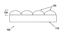
Figure 1A has described the explanatory view of the cross section of grating printed base plate (100).Particularly, grating printed base plate (100) has two parts: planar side (110) and raster-like side (120).It should be noted that grating printed base plate (100) is generally transparent, to allow, by grating printed base plate, observe image; At image surface printing images to grating lens in the situation that.Like this, by being printed on the upper image adhering to of planar side (110), the grating lens (130) of raster-like side (120) that can be by being assembled in grating printed base plate (100) is observed.Figure 1B has described the schematic top view of grating printed base plate (100), and wherein planar side is invisible.But, can see the row of the grating lens (130) of the raster-like side that is assembled in grating printed base plate.
Fig. 2 has described the explanatory view of master grating typography (200).The rotating cylinder (250,260) of printing machine (240) holding mobile, guiding and printing grating web media (271).Feeding grating web media (271) enters printing machine (240) from raw material source (280).Grating web media (271) has grating side (272) down, and smooth printed side (274) upward.During image (not shown) being printed on to the smooth printed side (274) of grating web media (271), impression rotating cylinder (250) and idle running rotating cylinder (260) interact with grating web media (271).
Referring now to Fig. 3 A, Fig. 3 A has described the parts of grating guiding rotating cylinder.In the left side of Fig. 3 A, shown the grating printed base plate (370, observe from top) of standard print roller (360) and supply.In the case of the grating lens (330) of grating printed base plate (370) outwardly, grating printed base plate (370) is attached to standard print roller (360).The structure (right side of Fig. 3 A) obtaining is grating guiding rotating cylinder (390).As shown in the right side of Fig. 3 A, grating lens (330) extends on the whole circumference of grating guiding rotating cylinder (390).Grating printed base plate (370) attaches to standard print roller (360), makes the limit of grating printed base plate (370) and the limit of printing rotating cylinder (360) form seam (395) closely.It should be noted that the arrangement of the grating lens (330) associated with grating printed base plate (370) can be parallel or perpendicular to the axis of printing rotating cylinder (360).An advantage of the present invention is, by using from the grating printed base plate (370) in grating printed base plate to be printed or other suitable source, can guarantee that the spacing of the groove on grating guiding rotating cylinder (390) accurately mates the spacing of grating printed base plate (not shown) to be printed.In addition, without manufacturing special cylinder/rotating cylinder.Can suitably and easily to the original cylinder of any given digital printer, transform.For example, grating printed base plate (370) may be installed on the cylinder of a part that has been machine.Seam (395) can be by applying bonding agent between the limit at grating printed base plate (370) and the limit of standard print roller (360) or other suitable reagent forms closely.As alternative, bonding agent can fully be placed between grating printed base plate (370) and standard print roller (360).
Also with reference to Fig. 3 B, Fig. 3 B is according to the indicative icon of the splicing edge of the grating printed base plate that is wound in conveyer or roller platen (360) of some embodiments of the present invention now.As shown in Figure 3A, grating printed base plate (370) surrounds the rounded face of standard print roller (360).For the arrangement of the grating lens (330) that guarantees grating printed base plate (370) is aimed at abreast with common axis, such as the cylinder axis perpendicular to standard print roller (360) (371), two relative limits of grating printed base plate (370) are spliced.Alternatively, a limit is formed as waveform patterns (372), such as rectangular patterns, and for example square pattern, and another limit is formed as contrary pattern (373).In this embodiment, the splicing on limit makes the arrangement of the grating lens (330) of grating printed base plate (370) be parallel to common axis line to aim at, as shown in Figure 3 B.Even if there is the not linear grating lens arrangement (330) of tangled shape of waveform segment of the splicing assurance grating printed base plate (370) on the limit of such waveform patterns, the grating lens of grating printed base plate (370) is arranged (330) and is also aimed at, to be supported in the conveying that is parallel to the grating printed base plate (100) of the vertical line of cylinder axis (371) during typography.Alternatively, aforesaid waveform patterns is by being used stamping machine to form, and stamping machine is with the blade with corresponding waveform patterns.
The simple structure of the grating guiding rotating cylinder as shown in Fig. 3 A signal is a main advantage that is better than the special roller with groove, and the latter is generally the grating printed base plate of each type of using in printing and prepares specially.In conventional embodiment, necessary with special groove rotating cylinder alternate standard rotating cylinder, or rely on simply standard rotating cylinder to prevent the misalignment of grating printed base plate during printing.Two selections are all expensive, and first is selected expensive reason to be special rotating cylinder and the labour that they need is installed; Second printing time and resource of selecting expensive reason to be high error rate and loss.In the present invention, first a part for the grating printed base plate for printing or other medium with suitable spacing are attached to printing rotating cylinder, are generally and are attached on idle running rotating cylinder or impression cylinder.After attached, because of the interaction between the grating associated with guiding rotating cylinder and printed medium (seeing Fig. 4 B and following description), at the printable grating printed base plate of top feeding of grating guiding rotating cylinder (390), will cause aiming at fast.
Fig. 4 A has described the application of grating guiding rotating cylinder (490) in printing machine (440).Grating web media (471) has when its grating side (472) down when moving between printing rotating cylinder (450,490).Grating side (472) directly interacts with grating guiding rotating cylinder (490).Grating rotating cylinder (490) is comprised of standard print roller (460) and grating printed base plate (470), and the grating back of the body is towards printing rotating cylinder (460).In the figure, top rotating cylinder is impression rotating cylinder (450), and bottom rotating cylinder is the grating guiding rotating cylinder (490) being superimposed upon on idle running rotating cylinder (460).
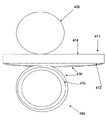
Fig. 4 B has schematically described the interactional near details of optical grating element, carry out the grating side (472) of the grating web media (471) of printing, with the grating printed base plate (470) associated with grating guiding rotating cylinder (490).As shown in the figure, general by getting a grating web media (471) of printing, what suitable spacing-permissions that realizes grating printed base plate (470) and grating web media (470) and grating led both associated grating lens (430) of rotating cylinder (490) locks step accurately.The advantage of this configuration includes but not limited to the remarkable minimizing of cost on the high-quality guiding rotating cylinder of preparation.As additional, at the grating lens associated with guiding rotating cylinder and the medium that printed, each other during interlock, there is the higher levels of power that is aligned to.During through impression rotating cylinder (450) below, printing occurs in smooth printed side (474).
Fig. 5 has described multiple rotating cylinder assemblies (525), and they appear in single printing machine (540).Each rotating cylinder assembly has two rotating cylinders, and one is impression rotating cylinder (550), and second is the raster-like guiding rotating cylinder (590) itself being comprised of idle running rotating cylinder (560) and a raster-like material (570).Each impression rotating cylinder (550) by the different piece of vision-mix or color be transported to through grating web media (571) on.Printing occurs in the smooth printed side (574) of grating web media (571), simultaneously, by printable grating web media (571) and and the associated grating printed base plate (570) of grating guiding rotating cylinder (590) between the interaction of gear forms, realize aligning.
Fig. 6 has described the flow chart for the production of the method for grating guiding rotating cylinder (600).Particularly, provide standard print roller (601), such as impression rotating cylinder and/or idle running rotating cylinder, an and grating medium, its spacing is with substantially the same by moving by the lead grating printed base plate of rotating cylinder of grating.Owing to being attached to first grating printed base plate of standard print roller and the similarity of carrying out between the grating printed base plate printing thereon, there is advantage.Such as the substantially the same feature of the physical orientation of spacing, grating lens and the size of described grating lens, allow the easily aligning of printable grating printed base plate along grating guiding rotating cylinder, thereby there is advantage.Shown in the next step of method for by the grating printed base plate providing and physically associated (603) of standard print roller.Shown in associated can by gluing, clamp and/or by any operation formation of a grating printed base plate piece that allows to provide associated with standard print roller (can for temporary transient associated).Finally, in another step (605), the feeding of printable grating printed base plate is entered to printing machine or other machine, and the grating guiding rotating cylinder wherein with the grating printed base plate piece providing can make the each grating printed base plate can with one or more similar characteristics aim at.
In an example embodiment of the present invention, employing has the HP Indigo printing machine ws4500 of 3D grating application, see http://h10010.www1.hp.com/wwpc/us/en/ga/WF05a/18972-18972-23625 7-90275-90271-3252083.html, it is incorporated into herein by reference.From the cutting of raw material grating web media, be used for a part for the grating web media of printing.The edge of this part is bonding and/or be attached at securely on the dummy roll of ws4500.Grating printed base plate bonding and/or that be attached to securely on the edge of roller completely or partially covers the surface of roller, and has the grating lens of the back of the body towards roller.Similarly, each substantially the same grating printed base plate is bonding and/or be attached to securely on all dummy rolls associated with ws4500.For starting grating printing, suitable image is selected for printing, such as 3D, and " upset " or any other image of being convenient to observe by grating lens.By with bonding and/or be attached to securely the substantially the same grating feeding medium of grating medium at least one roller by ws4500 printing machine.From the grating of grating guide roller and the grating from printable grating printed base plate, interact, to form the grating of interlocking interlock.This interlocking interlock allows the aligning of grating printed base plate in printing machine, and meanwhile, single coloured silk or multicolor printing occur in the smooth of feeding grating medium can printed side.Be printed on smooth can printed side the continuing of grating printed base plate,, from guiding rotating cylinder with from the grating of grating printed base plate, interact meanwhile, guarantee the suitable aligning of image.When printing operation completes, can from or can from dummy roll, not remove grating printed base plate.Ws4500 can be used in it has the condition of HP, or different grating printed base plates can be attached on the one or more rollers of HP-supply, to carry out another grating printing operation as described above.It should be noted that and can adjust similarly any thin slice feeding printing machine and/or rotating cylinder printing machine, to print on grating medium.
Although described the present invention with specific exact level, those skilled in the art will easily understand, and can, in the case of not departing from the spirit and scope of claims, implement various modification and replacement.Therefore, the embodiments described herein and be not intended to for example limit and relate to scope or the spirit of method of the present invention and relevant device.Bonding and/or be attached to securely guide material in standard print roller and nonessential be grating, as long as can be for making grating cylinder material or aiming at for the similar mediums printing.Advantage of the present invention comprises the ability of the grating printing that standard printing equipment is strict with for height.The present invention can save fund and time, and obtains the higher percentage of producing the finished product raster image that can be used for advertisement, distribution or other and various application.
By this application, by various forms, presented various embodiment of the present invention.Should be appreciated that the description of each form only for convenience and simplicity, should not be construed as to scope of the present invention can not be flexible restriction.
Although should be understood that for simple and clear object, some feature of the present invention has been described in different embodiment, described some feature of the present invention can combine at an embodiment.Conversely, although for succinct object, various feature of the present invention has been described in the environment of single embodiment, but also can provide respectively described various features of the present invention, or provide described various features of the present invention with any suitable sub-portfolio, or in describing embodiment, any other of the present invention suitably provide described various features of the present invention.Some feature of describing in the environment of various embodiment, what be not considered as these embodiment must obligato feature, unless this embodiment does not have these elements not work.
Although described in conjunction with specific embodiments the present invention, apparent, those skilled in the art know that manyly substitute, change and modification.Therefore, intention comprises that all these in spirit and the broad range that falls into claims substitute, change and modification.
All publication, patents and patent applications of mentioning in this description by reference entirety are incorporated into this description, as shown particularly and independently respectively that independently open, patent or patent application are incorporated into herein by reference.In addition, in this application, quote as proof or any confirmation of quoting, should not form and admit that this is cited as known technology of the present invention.Although use title before each several part, they should not form inevitable restriction.
Claims (20)
1. be used to the method for producing raster image and prepare grating guiding rotating cylinder, comprise:
Printing rotating cylinder and first grating printed base plate that printing machine is provided, described first grating printed base plate has relative limit, and described first grating printed base plate has the spacing being substantially equal to the second grating printed base plate using in described production;
Make described first grating printed base plate described printing rotating cylinder of reeling, described spacing is carried on the back towards described printing rotating cylinder, and described relative limit forms seam on described printing rotating cylinder; With
The grating printed base plate of described first coiling is attached to described printing rotating cylinder;
Wherein, described spacing is aimed at the manipulation of described second grating printed base plate in described printing machine.
2. method according to claim 1, is characterized in that, described production comprises the production of grating printing operation.
3. method according to claim 1, is characterized in that, described printing rotating cylinder selects the group of freely dally rotating cylinder and impression cylinder formation.
4. method according to claim 1, is characterized in that, described attached step comprises described first grating printed base plate is incorporated into described printing rotating cylinder.
5. method according to claim 1, is characterized in that, described manipulation comprises the position of using the described printing rotating cylinder with described first attached grating printed base plate to aim at described second grating printed base plate at described production period.
6. method according to claim 1, is characterized in that, described printing rotating cylinder is for multiple printing rotating cylinders of described production.
7. method according to claim 1, is characterized in that, described printing rotating cylinder is covered by described first grating printed base plate at least in part on its circumference.
8. method according to claim 1, is characterized in that, described first grating printed base plate has at second groove that grating printed base plate is aimed at described in described campaign chien shih.
9. method according to claim 1, is characterized in that, described method also comprises the first and second relative edges of the described first grating printed base plate that be shaped, to allow its splicing described during attached.
10. method according to claim 9, it is characterized in that, described method also comprises that described the first waveform patterns and described the second waveform patterns are opposite each other according to first-phase opposite side described in the first waveform pattern-forming with according to second-phase opposite side described in the second waveform pattern-forming.
11. methods according to claim 10, is characterized in that, described the first waveform patterns is square waveform pattern.
12. 1 kinds of external members, for printing rotating cylinder being prepared into the grating guiding rotating cylinder of printing machine, to print on grating printed base plate, described external member comprises:
First grating printed base plate, described first grating printed base plate has relative limit, and can be wound on described printing rotating cylinder, makes described relative limit form seam; With
Attached element, is configured to, when described first grating printed base plate is wound on described printing rotating cylinder, described first grating printed base plate is fixed on described printing rotating cylinder;
Wherein, in the processing procedure of described printing machine, described first fixing grating printed base plate aimed at second grating printed base plate.
13. external members according to claim 12, is characterized in that, described processing is included on described second grating printed base plate prints.
14. external members according to claim 12, is characterized in that, described fixing use adhesive material is carried out.
15. external members according to claim 12, is characterized in that, described printing rotating cylinder selects the group of freely dally rotating cylinder and impression cylinder formation.
16. external members according to claim 12, is characterized in that, the grating of described first and second grating printed base plates has at least one substantially the same spacing physical size substantially the same with at least one.
17. external members according to claim 12, is characterized in that, described attached element is securing member.
18. 1 kinds of methods for the preparation of grating printing machine, comprising:
Printing rotating cylinder and a raster-like medium of grating printing machine are provided, a described raster-like medium has two relative limits, and the grating alignment feature of a described raster-like medium is equal to the grating printed base plate using in described grating printing machine substantially;
Make a described raster-like media roll around described printing rotating cylinder, make described two relative limits form seam; With
The raster-like medium of a described coiling is attached to described printing rotating cylinder, make the grating alignment feature being associated with described raster-like medium back to described printing rotating cylinder, and the manipulation of aiming at described grating printed base plate when described grating printed base plate is processed in described grating printing machine.
19. methods according to claim 18, is characterized in that, described printing rotating cylinder is idle running rotating cylinder.
20. methods according to claim 18, is characterized in that, described attached step realizes by apply binding agent between described printing rotating cylinder and a described raster-like medium.
Applications Claiming Priority (4)
| Application Number | Priority Date | Filing Date | Title |
|---|---|---|---|
| US12927008P | 2008-06-16 | 2008-06-16 | |
| US61/129270 | 2008-06-16 | ||
| US61/129,270 | 2008-06-16 | ||
| PCT/IL2009/000596 WO2010004548A1 (en) | 2008-06-16 | 2009-06-16 | A method and an apparatus for processing a lenticular printing substrate |
Publications (2)
| Publication Number | Publication Date |
|---|---|
| CN102123866A CN102123866A (en) | 2011-07-13 |
| CN102123866B true CN102123866B (en) | 2014-05-07 |
Family
ID=41138930
Family Applications (1)
| Application Number | Title | Priority Date | Filing Date |
|---|---|---|---|
| CN200980131795.7A Expired - Fee Related CN102123866B (en) | 2008-06-16 | 2009-06-16 | A method and an apparatus for processing a lenticular printing substrate |
Country Status (8)
| Country | Link |
|---|---|
| US (1) | US9021947B2 (en) |
| EP (1) | EP2296889B1 (en) |
| JP (1) | JP5555229B2 (en) |
| KR (1) | KR101594118B1 (en) |
| CN (1) | CN102123866B (en) |
| BR (1) | BRPI0909937A2 (en) |
| CA (1) | CA2727688C (en) |
| WO (1) | WO2010004548A1 (en) |
Families Citing this family (28)
| Publication number | Priority date | Publication date | Assignee | Title |
|---|---|---|---|---|
| KR101594118B1 (en) | 2008-06-16 | 2016-02-15 | 휴먼아이즈 테크놀로지즈 리미티드 | A method and an apparatus for processing a lenticular printing substrate |
| CN102673097A (en) * | 2011-03-17 | 2012-09-19 | 深圳劲嘉彩印集团股份有限公司 | Three-dimensional printing equipment, printing method and packaging box |
| CN104460100B (en) * | 2014-11-26 | 2018-03-27 | 京东方科技集团股份有限公司 | Display base plate and display panel and preparation method thereof, display device |
| US10065441B2 (en) | 2015-09-01 | 2018-09-04 | Digimarc Corporation | Counterfeiting detection using machine readable indicia |
| WO2017132496A1 (en) | 2016-01-28 | 2017-08-03 | Tracer Imaging Llc | Product alignment using a printed relief |
| US10682837B2 (en) | 2017-06-09 | 2020-06-16 | The Proctor & Gamble Company | Method and compositions for applying a material onto articles |
| US10375306B2 (en) | 2017-07-13 | 2019-08-06 | Zillow Group, Inc. | Capture and use of building interior data from mobile devices |
| US10530997B2 (en) | 2017-07-13 | 2020-01-07 | Zillow Group, Inc. | Connecting and using building interior data acquired from mobile devices |
| US10643386B2 (en) | 2018-04-11 | 2020-05-05 | Zillow Group, Inc. | Presenting image transition sequences between viewing locations |
| US10708507B1 (en) | 2018-10-11 | 2020-07-07 | Zillow Group, Inc. | Automated control of image acquisition via use of acquisition device sensors |
| CA3058602C (en) | 2018-10-11 | 2023-01-24 | Zillow Group, Inc. | Automated mapping information generation from inter-connected images |
| US10809066B2 (en) | 2018-10-11 | 2020-10-20 | Zillow Group, Inc. | Automated mapping information generation from inter-connected images |
| US11243656B2 (en) | 2019-08-28 | 2022-02-08 | Zillow, Inc. | Automated tools for generating mapping information for buildings |
| US11164368B2 (en) | 2019-10-07 | 2021-11-02 | Zillow, Inc. | Providing simulated lighting information for three-dimensional building models |
| US11164361B2 (en) | 2019-10-28 | 2021-11-02 | Zillow, Inc. | Generating floor maps for buildings from automated analysis of visual data of the buildings' interiors |
| US10825247B1 (en) | 2019-11-12 | 2020-11-03 | Zillow Group, Inc. | Presenting integrated building information using three-dimensional building models |
| US11676344B2 (en) | 2019-11-12 | 2023-06-13 | MFTB Holdco, Inc. | Presenting building information using building models |
| US11405549B2 (en) | 2020-06-05 | 2022-08-02 | Zillow, Inc. | Automated generation on mobile devices of panorama images for building locations and subsequent use |
| US11514674B2 (en) | 2020-09-04 | 2022-11-29 | Zillow, Inc. | Automated analysis of image contents to determine the acquisition location of the image |
| US11592969B2 (en) | 2020-10-13 | 2023-02-28 | MFTB Holdco, Inc. | Automated tools for generating building mapping information |
| US11481925B1 (en) | 2020-11-23 | 2022-10-25 | Zillow, Inc. | Automated determination of image acquisition locations in building interiors using determined room shapes |
| US11252329B1 (en) | 2021-01-08 | 2022-02-15 | Zillow, Inc. | Automated determination of image acquisition locations in building interiors using multiple data capture devices |
| CA3142154A1 (en) | 2021-01-08 | 2022-07-08 | Zillow, Inc. | Automated determination of image acquisition locations in building interiors using multiple data capture devices |
| US11836973B2 (en) | 2021-02-25 | 2023-12-05 | MFTB Holdco, Inc. | Automated direction of capturing in-room information for use in usability assessment of buildings |
| US11790648B2 (en) | 2021-02-25 | 2023-10-17 | MFTB Holdco, Inc. | Automated usability assessment of buildings using visual data of captured in-room images |
| US11501492B1 (en) | 2021-07-27 | 2022-11-15 | Zillow, Inc. | Automated room shape determination using visual data of multiple captured in-room images |
| US11842464B2 (en) | 2021-09-22 | 2023-12-12 | MFTB Holdco, Inc. | Automated exchange and use of attribute information between building images of multiple types |
| US11830135B1 (en) | 2022-07-13 | 2023-11-28 | MFTB Holdco, Inc. | Automated building identification using floor plans and acquired building images |
Citations (4)
| Publication number | Priority date | Publication date | Assignee | Title |
|---|---|---|---|---|
| US3462226A (en) * | 1966-10-06 | 1969-08-19 | Eastman Kodak Co | Preregistration and layout of three-dimensional prints |
| EP0238043A2 (en) * | 1986-03-18 | 1987-09-23 | GAO Gesellschaft für Automation und Organisation mbH | Security document incoporating a security thread |
| WO1999012718A1 (en) * | 1997-09-11 | 1999-03-18 | Mikkelsen Oeystein | Lenticular pattern forming roll and method for making the roll |
| US6276269B1 (en) * | 1999-09-07 | 2001-08-21 | Lenticular Technologies, Llc | Guide roll for use in printing lenticular materials |
Family Cites Families (17)
| Publication number | Priority date | Publication date | Assignee | Title |
|---|---|---|---|---|
| US2317198A (en) * | 1940-02-23 | 1943-04-20 | Midland Steel Prod Co | Sheet metal forming equipment |
| US2362817A (en) * | 1942-09-28 | 1944-11-14 | Continental Can Co | Method of making sheet metal containers |
| US2724312A (en) * | 1952-05-07 | 1955-11-22 | John T Gruetzner | Means for obtaining three-dimensional photography |
| US3050649A (en) * | 1958-08-18 | 1962-08-21 | Amherst Metal Products Inc | Motor brush holder |
| US3301992A (en) * | 1963-08-14 | 1967-01-31 | Taylor Winfield Corp | Method for joining flat metal stock |
| US4925506A (en) * | 1988-07-15 | 1990-05-15 | Baker A Leroy | Printing plate mounting device and method |
| US5890430A (en) | 1990-11-14 | 1999-04-06 | Heidelberger Druckmaschinen Ag | Impression cylinder having a multiple diameter and a sheet guiding foil |
| DE4036252C1 (en) | 1990-11-14 | 1992-01-02 | Heidelberger Druckmaschinen Ag, 6900 Heidelberg, De | |
| JP2779149B2 (en) | 1995-10-31 | 1998-07-23 | 忠男 宇野 | Printing equipment |
| JP3448200B2 (en) | 1998-01-14 | 2003-09-16 | 三菱重工業株式会社 | Impression cylinder for sheet-fed printing press |
| JP3817090B2 (en) * | 1999-06-30 | 2006-08-30 | 富士写真フイルム株式会社 | Printing plate mounting equipment |
| US6922201B2 (en) * | 2001-12-05 | 2005-07-26 | Eastman Kodak Company | Chronological age altering lenticular image |
| JP2006289496A (en) * | 2005-03-17 | 2006-10-26 | Seiko Epson Corp | Cylindrical shaft and method of manufacturing the same |
| JP2007160352A (en) * | 2005-12-14 | 2007-06-28 | Seiko Epson Corp | Cylindrical shaft, manufacturing method of cylindrical shaft, and fixing roller using cylindrical shaft |
| JP2008132721A (en) | 2006-11-29 | 2008-06-12 | Nitto Denko Corp | Cushioning sheet for printing apparatus, printing apparatus and printing method |
| KR100899310B1 (en) | 2006-12-08 | 2009-05-26 | 신화인터텍 주식회사 | Apparatus for fabricationg optical sheet, method for fabricating optical sheet, and optical sheet fabricated using the same |
| KR101594118B1 (en) | 2008-06-16 | 2016-02-15 | 휴먼아이즈 테크놀로지즈 리미티드 | A method and an apparatus for processing a lenticular printing substrate |
-
2009
- 2009-06-16 KR KR1020107029927A patent/KR101594118B1/en active IP Right Grant
- 2009-06-16 US US12/999,314 patent/US9021947B2/en active Active
- 2009-06-16 CN CN200980131795.7A patent/CN102123866B/en not_active Expired - Fee Related
- 2009-06-16 BR BRPI0909937A patent/BRPI0909937A2/en not_active Application Discontinuation
- 2009-06-16 WO PCT/IL2009/000596 patent/WO2010004548A1/en active Application Filing
- 2009-06-16 EP EP09787443.2A patent/EP2296889B1/en not_active Not-in-force
- 2009-06-16 CA CA2727688A patent/CA2727688C/en not_active Expired - Fee Related
- 2009-06-16 JP JP2011514197A patent/JP5555229B2/en not_active Expired - Fee Related
Patent Citations (4)
| Publication number | Priority date | Publication date | Assignee | Title |
|---|---|---|---|---|
| US3462226A (en) * | 1966-10-06 | 1969-08-19 | Eastman Kodak Co | Preregistration and layout of three-dimensional prints |
| EP0238043A2 (en) * | 1986-03-18 | 1987-09-23 | GAO Gesellschaft für Automation und Organisation mbH | Security document incoporating a security thread |
| WO1999012718A1 (en) * | 1997-09-11 | 1999-03-18 | Mikkelsen Oeystein | Lenticular pattern forming roll and method for making the roll |
| US6276269B1 (en) * | 1999-09-07 | 2001-08-21 | Lenticular Technologies, Llc | Guide roll for use in printing lenticular materials |
Also Published As
| Publication number | Publication date |
|---|---|
| CN102123866A (en) | 2011-07-13 |
| JP5555229B2 (en) | 2014-07-23 |
| US20110100243A1 (en) | 2011-05-05 |
| KR101594118B1 (en) | 2016-02-15 |
| KR20110038656A (en) | 2011-04-14 |
| EP2296889A1 (en) | 2011-03-23 |
| US9021947B2 (en) | 2015-05-05 |
| JP2011524288A (en) | 2011-09-01 |
| EP2296889B1 (en) | 2015-04-01 |
| CA2727688A1 (en) | 2010-01-14 |
| CA2727688C (en) | 2017-03-14 |
| BRPI0909937A2 (en) | 2015-10-20 |
| WO2010004548A1 (en) | 2010-01-14 |
Similar Documents
| Publication | Publication Date | Title |
|---|---|---|
| CN102123866B (en) | A method and an apparatus for processing a lenticular printing substrate | |
| US8964297B2 (en) | Thin film high definition dimensional image display device and methods of making same | |
| US20100134895A1 (en) | Thin film high definition dimensional image display device and methods of making same | |
| US10889107B2 (en) | Product alignment using a printed relief | |
| US6624946B2 (en) | In-line lenticular film manufacturing having a selected web orientation | |
| CN102653176A (en) | Dot formation positioning device, recording method, setting method, and recording program | |
| CN103862863A (en) | Image quality by printing frequency adjustment using belt surface velocity measurement | |
| WO2006073961A1 (en) | Continuous lenticular image label web | |
| JP2002539979A (en) | In-line production of solid materials | |
| CN1271319A (en) | Application of substances on a package | |
| US20170008315A1 (en) | Flatbed printer assembly | |
| CN105966055A (en) | Magnetic printing equipment, magnetic orientation device and magnetic printing method | |
| CN104487251B (en) | The method of the accurate alignment imprinted in rotary printing made of different inks | |
| CN101754858B (en) | Stereoscopic image printing article, image printing article, their forming apparatus, and forming method | |
| CN101992586B (en) | Holographic positioning molding method and system | |
| US9283728B2 (en) | Removal device for removal of labels, label and method for applying glue to a label | |
| CN102438836A (en) | Apparatus for printing a material web | |
| CN1294554A (en) | Method and device for coating sheets and use of said method | |
| KR20080108979A (en) | Feeding system for image forming machine | |
| US9956797B2 (en) | Web feeding of weak media | |
| JP6884362B2 (en) | Label with mount, printing device, sticking device | |
| KR102602866B1 (en) | Method For Manufacturing Wrapping Paper For Marine Products Using Corrugated Cardboard | |
| EP2769835A1 (en) | Method for manufacturing a film for a 3d lens | |
| US20220105740A1 (en) | Multi-Color Retransfer Single Stamping System And Method | |
| CN206733795U (en) | A kind of 3D solids opal printing equipment and system |
Legal Events
| Date | Code | Title | Description |
|---|---|---|---|
| C06 | Publication | ||
| PB01 | Publication | ||
| C10 | Entry into substantive examination | ||
| SE01 | Entry into force of request for substantive examination | ||
| C14 | Grant of patent or utility model | ||
| GR01 | Patent grant | ||
| CF01 | Termination of patent right due to non-payment of annual fee |
Granted publication date: 20140507 Termination date: 20200616 |
|
| CF01 | Termination of patent right due to non-payment of annual fee |