CN102123775A - Simulated-moving-bed separation method and device with modulated tapped-off fluid flow - Google Patents
Simulated-moving-bed separation method and device with modulated tapped-off fluid flow Download PDFInfo
- Publication number
- CN102123775A CN102123775A CN2009801321897A CN200980132189A CN102123775A CN 102123775 A CN102123775 A CN 102123775A CN 2009801321897 A CN2009801321897 A CN 2009801321897A CN 200980132189 A CN200980132189 A CN 200980132189A CN 102123775 A CN102123775 A CN 102123775A
- Authority
- CN
- China
- Prior art keywords
- zone
- bypass line
- column plate
- extract
- bypass
- Prior art date
- Legal status (The legal status is an assumption and is not a legal conclusion. Google has not performed a legal analysis and makes no representation as to the accuracy of the status listed.)
- Granted
Links
Images


Classifications
-
- B—PERFORMING OPERATIONS; TRANSPORTING
- B01—PHYSICAL OR CHEMICAL PROCESSES OR APPARATUS IN GENERAL
- B01D—SEPARATION
- B01D15/00—Separating processes involving the treatment of liquids with solid sorbents; Apparatus therefor
- B01D15/08—Selective adsorption, e.g. chromatography
- B01D15/10—Selective adsorption, e.g. chromatography characterised by constructional or operational features
- B01D15/18—Selective adsorption, e.g. chromatography characterised by constructional or operational features relating to flow patterns
- B01D15/1814—Selective adsorption, e.g. chromatography characterised by constructional or operational features relating to flow patterns recycling of the fraction to be distributed
- B01D15/1821—Simulated moving beds
- B01D15/1828—Simulated moving beds characterized by process features
- B01D15/1835—Flushing
-
- C—CHEMISTRY; METALLURGY
- C07—ORGANIC CHEMISTRY
- C07C—ACYCLIC OR CARBOCYCLIC COMPOUNDS
- C07C7/00—Purification; Separation; Use of additives
- C07C7/12—Purification; Separation; Use of additives by adsorption, i.e. purification or separation of hydrocarbons with the aid of solids, e.g. with ion-exchangers
-
- C—CHEMISTRY; METALLURGY
- C10—PETROLEUM, GAS OR COKE INDUSTRIES; TECHNICAL GASES CONTAINING CARBON MONOXIDE; FUELS; LUBRICANTS; PEAT
- C10G—CRACKING HYDROCARBON OILS; PRODUCTION OF LIQUID HYDROCARBON MIXTURES, e.g. BY DESTRUCTIVE HYDROGENATION, OLIGOMERISATION, POLYMERISATION; RECOVERY OF HYDROCARBON OILS FROM OIL-SHALE, OIL-SAND, OR GASES; REFINING MIXTURES MAINLY CONSISTING OF HYDROCARBONS; REFORMING OF NAPHTHA; MINERAL WAXES
- C10G25/00—Refining of hydrocarbon oils in the absence of hydrogen, with solid sorbents
- C10G25/06—Refining of hydrocarbon oils in the absence of hydrogen, with solid sorbents with moving sorbents or sorbents dispersed in the oil
-
- C—CHEMISTRY; METALLURGY
- C10—PETROLEUM, GAS OR COKE INDUSTRIES; TECHNICAL GASES CONTAINING CARBON MONOXIDE; FUELS; LUBRICANTS; PEAT
- C10G—CRACKING HYDROCARBON OILS; PRODUCTION OF LIQUID HYDROCARBON MIXTURES, e.g. BY DESTRUCTIVE HYDROGENATION, OLIGOMERISATION, POLYMERISATION; RECOVERY OF HYDROCARBON OILS FROM OIL-SHALE, OIL-SAND, OR GASES; REFINING MIXTURES MAINLY CONSISTING OF HYDROCARBONS; REFORMING OF NAPHTHA; MINERAL WAXES
- C10G25/00—Refining of hydrocarbon oils in the absence of hydrogen, with solid sorbents
- C10G25/12—Recovery of used adsorbent
-
- C—CHEMISTRY; METALLURGY
- C10—PETROLEUM, GAS OR COKE INDUSTRIES; TECHNICAL GASES CONTAINING CARBON MONOXIDE; FUELS; LUBRICANTS; PEAT
- C10G—CRACKING HYDROCARBON OILS; PRODUCTION OF LIQUID HYDROCARBON MIXTURES, e.g. BY DESTRUCTIVE HYDROGENATION, OLIGOMERISATION, POLYMERISATION; RECOVERY OF HYDROCARBON OILS FROM OIL-SHALE, OIL-SAND, OR GASES; REFINING MIXTURES MAINLY CONSISTING OF HYDROCARBONS; REFORMING OF NAPHTHA; MINERAL WAXES
- C10G53/00—Treatment of hydrocarbon oils, in the absence of hydrogen, by two or more refining processes
- C10G53/02—Treatment of hydrocarbon oils, in the absence of hydrogen, by two or more refining processes plural serial stages only
- C10G53/08—Treatment of hydrocarbon oils, in the absence of hydrogen, by two or more refining processes plural serial stages only including at least one sorption step
-
- C—CHEMISTRY; METALLURGY
- C10—PETROLEUM, GAS OR COKE INDUSTRIES; TECHNICAL GASES CONTAINING CARBON MONOXIDE; FUELS; LUBRICANTS; PEAT
- C10G—CRACKING HYDROCARBON OILS; PRODUCTION OF LIQUID HYDROCARBON MIXTURES, e.g. BY DESTRUCTIVE HYDROGENATION, OLIGOMERISATION, POLYMERISATION; RECOVERY OF HYDROCARBON OILS FROM OIL-SHALE, OIL-SAND, OR GASES; REFINING MIXTURES MAINLY CONSISTING OF HYDROCARBONS; REFORMING OF NAPHTHA; MINERAL WAXES
- C10G2300/00—Aspects relating to hydrocarbon processing covered by groups C10G1/00 - C10G99/00
- C10G2300/10—Feedstock materials
- C10G2300/1096—Aromatics or polyaromatics
-
- C—CHEMISTRY; METALLURGY
- C10—PETROLEUM, GAS OR COKE INDUSTRIES; TECHNICAL GASES CONTAINING CARBON MONOXIDE; FUELS; LUBRICANTS; PEAT
- C10G—CRACKING HYDROCARBON OILS; PRODUCTION OF LIQUID HYDROCARBON MIXTURES, e.g. BY DESTRUCTIVE HYDROGENATION, OLIGOMERISATION, POLYMERISATION; RECOVERY OF HYDROCARBON OILS FROM OIL-SHALE, OIL-SAND, OR GASES; REFINING MIXTURES MAINLY CONSISTING OF HYDROCARBONS; REFORMING OF NAPHTHA; MINERAL WAXES
- C10G2400/00—Products obtained by processes covered by groups C10G9/00 - C10G69/14
- C10G2400/02—Gasoline
-
- C—CHEMISTRY; METALLURGY
- C10—PETROLEUM, GAS OR COKE INDUSTRIES; TECHNICAL GASES CONTAINING CARBON MONOXIDE; FUELS; LUBRICANTS; PEAT
- C10G—CRACKING HYDROCARBON OILS; PRODUCTION OF LIQUID HYDROCARBON MIXTURES, e.g. BY DESTRUCTIVE HYDROGENATION, OLIGOMERISATION, POLYMERISATION; RECOVERY OF HYDROCARBON OILS FROM OIL-SHALE, OIL-SAND, OR GASES; REFINING MIXTURES MAINLY CONSISTING OF HYDROCARBONS; REFORMING OF NAPHTHA; MINERAL WAXES
- C10G2400/00—Products obtained by processes covered by groups C10G9/00 - C10G69/14
- C10G2400/30—Aromatics
Abstract
Provided is a method of separating a charge F by simulated-moving-bed adsorption in an SMB device comprising at least one zone 1 for desorption of the compounds produced in the extract, a zone 2 for desorption of the compounds produced in the raffinate, a zone 3 for adsorption of the compounds produced in the extract, a zone 4 located between the raffinate withdrawal and the desorbent feed, the device including external tap-off lines Li/i+1 directly joining two successive plates Pi, Pi+1, in which device the degree of opening of means for restricting the purge flow rate of the tap-off lines Li/i+1 is modified sequentially so that: 1) in an operating zone in which at least one tap-off line is closed, an oversynchronicity of the purge flow rate is established over all the non-closed tap-off lines belonging to the zone in question, said oversynchronicity being defined by the following formula: S=a+b(nf/nt) in which the constant a is a constant between -5 and 5, and b is a constant between 40 and 100; 2) if there is no closed tap-off line in the zone in question (in other words if all the tap-off lines of the zone are open), then a flow rate corresponding to the synchronicity to within +- 8% is then established in all the purge lines of said zone.
Description
Invention field
The present invention relates to be difficult to the separation field of the natural or chemical products of separated.Use class methods and the relevant apparatus that is known as simulated moving bed process or separator with the simulation counter-flow pattern or with simulation and stream mode, they use common term " SMB " expression hereinafter.
Related field concrete but nonexcludability example are:
● normal paraffin hydrocarbons separates with branched paraffin, cycloalkanes and aromatic hydrocarbons;
● olefin/paraff iotan is separated;
● paraxylene separates with other C8 aromatic isomers;
● meta-xylene separates with other C8 aromatic isomers;
● ethylbenzene separates with other C8 aromatic isomers.
Except that refinery and petrochemical complex, also have many other application; Specifiable these example comprises that glucose is separated, the separation of Cresol Isomers Using, optical isomer separation etc.
Prior art
It is as known in the art that SMB separates.Generally speaking, comprise at least three districts with the tower of simulation moving-bed mode operation, may four or five districts, the continuous bed of each free some of described district constitutes, and each district delimited by its position between supply centre and off-take point.Generally, supply at least one charging F that wants fractionation and strippant D(is called eluant, eluent sometimes to the SMB tower), and from described tower, take out at least one raffinate R and extract E.
Supply and off-take point change in time, the general value that is equivalent to a bed that moves in the same direction.
By definition, each operating space figure denote:
● zone 1=injecting strippant D and taking out being used between the extract E from the zone of extract desorb compound;
● zone 2=taking out extract E and injecting being used between the charging F that wants fractionation from the zone of raffinate desorb compound;
● zone 3=being used between charging injection and raffinate R taking-up from the zone of extract adsorption compound;
● preferably, the zone 4 between raffinate taking-up and strippant injection.
Prior art is described the various apparatus and method of the simulation moving-bed separation that can implement charging in detail.
Can quote following patent: US-2 985 589, US-3 214 247, US-3 268 605, US-3 592 612, US-4 614 204, US-4 378 292, US-5 200 075, US-5 316 821 especially.These patents are also described the operation of SMB in detail.
The SMB device generally comprises at least one (general two) tower, and it is divided into a plurality of adsorbent bed A in succession
i, described bed is by column plate P
iSeparate each column plate P
iComprise one, two or four chambers, mean the operation in tandem that to supply charging or inject strippant and extract raffinate or extract.
Single chamber can carry out 4 kinds of operations, but the present invention relates to the tower that each column plate has 2 chambers.When using two chambers when (may be used for the injection or the taking-up of one or more logistics separately), have many solutions.For example, charging or desorb implant operation can be carried out in first Room, and another chamber carries out raffinate or extract takes out operation.Another possible situation comprises uses a chamber to be used for injecting feeding and taking-up raffinate, and another chamber is responsible for injecting strippant and is taken out extract.These two examples are not restrictive; Other application of these two chambers also is possible.
Distributing fluids and the control device of extracting fluid from SMB generally are one of technology of following two kinds of main types:
● each column plate has a plurality of controlled switch valves with supply or taking-up fluid, the corresponding column plate of the general next-door neighbour of described valve.Each column plate P
iGenerally comprise at least 4 two-way valves, with the supply of implementing fluid F and D respectively and the taking-up of fluid E and R with on-off control;
● or being used on this group column plate supply or take out the how logical revolving valve (multi-way rotary valve) of fluid.
The invention belongs to and use in the scope of a plurality of valves with the SMB device of the supply of guaranteeing various fluids and taking-up.
Each column plate P
iGenerally comprise a plurality of distributor-blenders-extractor dish, be called " DME column plate " by distribution/extraction pipeline or system supply.This column plate can have any kind and any how much.They are generally divided into the corresponding dish of adjacent block with the cross section of this tower, for example have the dish of dihedral block, as patent US-6 537 451, and those shown in Fig. 8, or have the dish of parallel block, those described in patent US-6 797 175.
Knockout tower of the present invention preferably includes the DMF column plate with parallel block and asymmetric feed type.
Distribution requirement on each is collected from the main stream of last bed, may inject therein and replenish or secondaiy fluidic, described two fluids are mixed as far as possible fully, maybe may remove fluid that a part collects, extract it it being exported this device, and may on next bed, redistribute fluid.
The total problem of all SMB devices is to make accommodating fluid and takes out the minimum contamination that is produced by liquid each zone of the circuit that fluid uses from column plate in the change process of the supply of SMB run duration and off-take point.
In fact, when in the operation sequence process, being used for to column plate P
iIt is out-of-date that the pipeline of feed, chamber or zone no longer include flow of process fluid, and it becomes the dead band, and wherein fluid stagnation is only flowed through at another process fluid and just moved at that time again.Because the operation of SMB, its at this moment be generally be stuck in consider the different process fluid of fluid in the pipeline.
Compare with the ideal operation of avoiding therein forming discontinuity, it forms the mixing of different substantially fluids or the disturbance that the circulation in short time interval causes the CONCENTRATION DISTRIBUTION of institute's consideration of regional.
Another problem is because the minimum pressure reduction between each zone of this column plate, between each zone of single column plate, and more general possible recirculation in the whole distribution/extraction system of single column plate, this compares with ideal operation again and shows interference.
In order to overcome these problems relevant with recirculation and dead band, various solutions are known in the prior art:
A) proposed to use relative distribution/extraction system of washing given column plate than the strippant or the required product of pure state.In fact this technology can prevent the pollution of required product in its leaching process.But because the composition of flushing liquor is different from the liquid of its displacement very much, this causes the composition discontinuity that is unfavorable for desirable operation.The general short-term flushing that realizes having the high concentration gradient of this first flushing variant.These short-term flushings are accurately short influences with restriction composition discontinuity.
B) described in another solution such as patent US-5 972 224 and the US-6 110 364, it is, the main major part of stream is sent into this tower and shifted out its fraction (be generally this mainly flow 1% to 20%) via the external bypass for fluid road between the column plate in succession.Use from the stream of top column plate general continuous the carrying out of this flushing,, but constantly be rinsed so that the pipeline of this distribution/extraction system and zone no longer are " dead " to the distribution/extraction system of column plate.
In Fig. 2 of patent FR-2 772 634, shown this system of washing continuously that uses via bypass line.This bypass line generally has minor diameter and comprises small diameter valve, and this reduces the cost of this system.
According to the disclosure of patent US-5 972 224 and US-6 110 364, with distribution/extraction system of forming the given column plate of liquid wash that is in close proximity to the liquid (liquid that exists in the distribution system or in this column plate, circulate) of being replaced.Therefore, the mixing of the fluid that composition is different minimizes and reduces the composition discontinuity.
For this reason, patent US-5 972 224 and US-6 110 364 be recommended in the bypass line use irrigation flow rate so that in the main stream of rate travel in each bypass line and SMB the propelling speed of concentration gradient basic identical.At this moment it be known as " synchronously " flushing or " flow velocity synchronously " flushing.Therefore, carry out the flushing of various pipelines and volume with the essentially identical fluid of forming with therein of liquid, the liquid that moves in bypass line is that wherein the composition with main stream is that essentially identical point is introduced again.
Because therefore little or zero-dose gradient, flushing are synchronous in long-time.
According to the disclosure of this patent, when from column plate P
iTo next column plate P
I+1Irrigation flow rate QS
I/i+1When equaling V/ST, flushing is known as " synchronous ", and wherein V is column plate P
i(be V
i) and P
I+1(be V
I+1) the volume of distribution system and the volume of the bypass line between this two column plates (be VL
I/i+1) cumulative volume, the switching time that ST is SMB between twice of supply/extraction switches in succession.
Therefore, we have " flow velocity synchronously "=QS
I/i+1=(V
i+ V
I+1+ VL
I/i+1)/ST, wherein:
● QS
I/i+1=from column plate P
nTo adjacent tray (general below) P
I+1Irrigation flow rate;
● V
i=column plate P leaves away
iThe volume of distribution/extraction system;
● V
I+1=arrival column plate P
I+1The volume of distribution/extraction system;
● VL
I/i+1=P
iWith P
I+1Between the volume of bypass line;
● ST=switching time.
General by be fit to each regional controllable rate (50% to 150% of the synchronous flow velocity in these zones, be desirably synchronous flow velocity 100%) flushing washes synchronously.Control the flow velocity in the bypass line in these 4 SMB zones by the adjusting device in each bypass line.
For example, the technical staff can use 90% flow velocity of synchronous flow velocity in all these zones, or 110% or for synchronous flow velocity near any other value of 100%.But when having adjusting device, according to the disclosure of the patent of above quoting, the technical staff can select control to meet the flow velocity in these 4 zones of synchronous flow velocity (synchronously flow velocity 100%) fully naturally.
The separation that an example of industrial very important SMB separator relates to the C8 aromatic fraction has technical purity with generation, the paraxylene of general at least 99.7 weight % purity and be rich in the raffinate of ethylbenzene, ortho-xylene and meta-xylene.
Two embodiments above quoting can realize the technical purity target.But, the applicant can show, although the disclosure of patent US-5 972 224 and US-6 110 364 " flushing synchronously " compared with prior art provides certain improvement, but surprisingly, the rule of various flow velocitys that still can be by improving this regulation bypass line is further improved the function and the performance of simulated mobile bed separation process.
Description of drawings
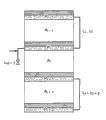
Fig. 1 shows 3 continuous beds, P
I-1, P
i, P
I+1, they constitute the part of simulation moving-bed tower (SMB).Effluent takes out the upstream that pipeline (raffinate or extract) is positioned at the isolating valve of bypass line.Supply line (being used for charging or strippant) is positioned at the isolating valve downstream.
Fig. 2 a is presented at the injection situation in the structure of tower of Fig. 1; Fig. 2 b is presented at the taking-up situation in the structure of tower of Fig. 1.
Fig. 3 be presented at fixing strippant flow velocity, charging flow velocity, production paraxylene purity and under switching time as each SMB changes of properties with PX yield (R) tolerance of the function of the synchronism (S) of all the untight bypass lines in the closed area not, other regional bypass line group keeps 100% synchronism.
The curve that contains rhombus is represented zone 1;
Contain foursquare curve and represent zone 2;
Contain leg-of-mutton curve and represent zone 3;
Contain circular curve and represent zone 4.
Fig. 4 shows 3 continuous beds, P
I-1, P
i, P
I+1, they constitute the part of simulation moving-bed tower (SMB).Effluent takes out the downstream that pipeline (raffinate or extract) is positioned at the isolating valve of bypass line.Supply line (being used for charging or strippant) is positioned at the isolating valve upstream.
Fig. 5 a is presented at the injection situation in the structure of tower of Fig. 4; Fig. 5 b is presented at the taking-up situation in the structure of tower of Fig. 4.
Fig. 6 be presented at fixing strippant flow velocity, charging flow velocity, production paraxylene purity and under switching time as the SMB changes of properties with PX yield (R) tolerance of the function of the synchronism (S) of all the untight bypass lines in each zone, the untight bypass line group in other zone keeps 100% synchronism.
The curve that contains rhombus is represented zone 1;
Contain foursquare curve and represent zone 2;
Contain leg-of-mutton curve and represent zone 3;
Contain circular curve and represent zone 4.
The invention summary
The objective of the invention is to compare the performance of improving simulated mobile bed separation process with the disclosure among the US-6 110 364 with patent US-5 972 224.
The invention still further relates to by having the flushing over a long time of little or zero-dose gradient, that uses supply and extract a plurality of controlled switch two-way valve that the SMB process fluid uses improvedly is used for the simulation moving-bed device that separates.
Find surprisingly, the operation of the ideal of bypass line does not correspond to the strict synchronous flow velocity in all operations district of SMB, but corresponding to different with the zone of SMB and represent in some cases may be basically or basically the flow velocity of supersynchronous property (super-synchronicity) not.
Term " supersynchronous property " expression surpasses the value of the value at least 10% corresponding with synchronism, and represents with the percentage that is higher than described synchronism.More properly, define described supersynchronous property by following formula:
Supersynchronous property (%)=100 * [(actual flow velocity in the bypass line of being considered/synchronism flow velocity)-1]
More properly, the present invention is directed to each zoning bypass flow rates of SMB device, it comprises the distinctive supersynchronous property to a certain degree of institute's consideration of regional.
This causes the optimization of the complexity of this group bypass flow velocity, its both with consideration SMB zone relevant (and for example seen in the as detailed below), relevant with the sealing bypass pipe way in the described zone again.In prior art is open, do not mention this technical problem fully, the knowledge in its formation SMB class methods field and the marked improvement of skill.
Therefore, the present invention relates to be used for simulation moving-bed (SMB) separation method of charging F in having the SMB device of at least one tower, described tower is by by the column plate P of each self-contained distribution/extraction system
iThe a plurality of adsorbent beds that separate constitute, in the method, supply charging F and strippant D, and take out at least one extract E and at least one raffinate R, supply and off-take point process ST switching time in time move the value that is equivalent to an adsorbent bed, and a plurality of operating spaces of definite SMB, particularly following 4 main region:
● the zone 1 of the compound that is used for the desorb extract between supply strippant D and taking-up extract E;
● in the zone 2 of taking out the compound that is used for the desorb raffinate between extract E and the supply charging F;
● the zone 3 of the compound that is used for adsorbing and extracting liquid between supply charging and taking-up raffinate R;
● in the zone 4 of taking out between raffinate R and the supply strippant D;
This device further comprises two of direct connections column plate P in succession
i, P
I+1Can wash the external bypass for fluid road L of described column plate
I/i+1, each bypass line L wherein
I/i+1Comprise the automation equipment that is used to regulate irrigation flow rate, the opening degree of described adjusting device is by following two rule predeterminings:
1) exist therein in the operating space of at least one sealing bypass line, set up the supersynchronous property of irrigation flow rate belonging in all bypass lines of consideration of regional, define described supersynchronous property by following formula:
S?=?a?+?b(nf/nt)
Wherein a is-5 to 5 constant, and b is 40 to 100 constant, and it multiply by at the sealing bypass pipe way (nf) of institute's consideration of regional and the ratio of bypass line sum (nt);
2) if there is not the bypass line (in other words) of sealing in institute's consideration of regional if all bypass lines that should the zone all open, then in all flushing lines in described zone foundation corresponding to the flow velocity of synchronism ± 8%;
The synchronism flow velocity is defined as (V
i+ V
I+1+ VL
I/i+1)/ST, wherein symbol
V
iRepresent to leave away column plate P
iThe volume of distribution/extraction system;
V
I+1Expression arrives column plate P
I+1The volume of distribution/extraction system;
VL
I/i+1Expression P
iWith P
I+1Between the volume of bypass line;
And ST represents switching time.
The invention still further relates to the method that is used to regulate each the regional irrigation flow rate that constitutes the SMB tower, it can followingly be stipulated:
1) the synchronism stuck-at-00% of the untight bypass line group by making other zone obtains the optimal synchronisation on the given area;
2) give the optimal synchronisation that obtains in the previous step to each zone.
At last, method of the present invention more is specially adapted to the paraxylene in the C8 aromatic hydrocarbons mixture or the separation of meta-xylene.Clearly, these two application examples never are restrictive, and other application is possible, particularly in the field of separation of normal paraffins and isoparaffin or positive alkene and isoalkene.
The specific embodiment
In order to improve the separating property that can produce by the SMB technology, the method that the present invention proposes to be used in having the SMB device of at least one tower to make charging F simulation moving-bed (SMB) to separate, described tower is by by the column plate P of each self-contained distribution/extraction system
iThe a plurality of adsorbent beds that separate constitute, in the method, supply charging F and strippant D, and take out at least one extract E and at least one raffinate R, supply and off-take point process ST switching time in time move the value that is equivalent to an adsorbent bed, and a plurality of operating spaces of definite SMB, particularly following 4 main region:
● the zone 1 of the compound that is used for the desorb extract between supply strippant D and taking-up extract E;
● in the zone 2 that is used for desorb raffinate compound of taking out between extract E and the supply charging F;
● the zone 3 of the compound that is used for adsorbing and extracting liquid between supply charging and taking-up raffinate R;
● in the zone 4 of taking out between raffinate R and the supply strippant D;
This device further comprises two of direct connections column plate P in succession
i, P
I+1Can wash the external bypass for fluid road L of described column plate
I/i+1,
Each bypass line L wherein
I/i+1Comprise the automation equipment that is used to regulate irrigation flow rate.
Directly connect two column plate P in succession
i, P
I+1External bypass for fluid road L
I/i+1At column plate P
iAnd P
I+1Between bed belong to described zone and the time be considered to belong to described zone.When the flow velocity in this bypass line was zero, bypass section was considered to seal.Can use any technique device of the flow velocity that can eliminate in bypass line, implement this sealing as switch valve, flow rate regulating valve or check-valves.
The opening degree of described adjusting device is by following two rule predeterminings:
1) exist therein in the operating space of at least one sealing bypass line, set up the supersynchronous property of irrigation flow rate belonging in all untight bypass lines of consideration of regional, described supersynchronous property is 10% to 100%;
2) if there is not the bypass line (in other words) of sealing in institute's consideration of regional, then in all bypass lines in described zone, set up corresponding to synchronism ± 8% flow velocity preferably ± 5% if all bypass lines that should the zone all open;
The synchronism flow velocity is defined as (V
i+ V
I+1+ VL
I/i+1)/ST, wherein symbol
V
iRepresent to leave away column plate P
iThe volume of distribution/extraction system;
V
I+1Expression arrives column plate P
I+1The volume of distribution/extraction system;
VL
I/i+1Expression P
iWith P
I+1Between the volume of bypass line;
And ST represents switching time.
According to above-mentioned rule, it being understood that whether the irrigation flow rate of bypass line in the given operating space exists at least one sealing bypass line relevant substantially with in the described zone.
More properly, the supersynchronous property S that wherein has a untight bypass line in zone of at least one sealing bypass line is defined by the ratio of the bypass line sum (nt) in the sealing bypass pipe way (nf) in institute's consideration of regional and this zone (being the bed number in the described zone).
Supersynchronous property S is defined as the percentage that uses following formula:
S?=?a?+?b(nf/nt)
Wherein:
A is-5 to 5 constant,
B is 40 to 100 constant, and it multiply by the sealing bypass pipe way (nf) of institute's consideration of regional and the ratio between the bypass line sum (nt).
Deep experimental study shows, coefficient b can be associated with bed sum (Nt) in this device by the following relationship formula:
B=(the bed sum in the 1320/SMB device).
Bypass line in the sealing given area has several reasons.Especially, fluid (charging or strippant) is being injected column plate P
iThe time, use filling line.This pipeline connects to the bypass line that links to each other with described column plate, i.e. bypass line L
I/i-1Or bypass line L
I/i+1The whichever bypass line connects to used filling line, and other technology that at this moment needs to use switch valve, flow velocity mediation valve or any check-valves maybe can eliminate flow velocity is sealed described pipeline and flowed to column plate P rightly with the fluid of guaranteeing to inject
i
In the same manner, from column plate P
iWhen taking out effluent (extract or raffinate), use and take out pipeline.This taking-up pipeline connects to the bypass line that links to each other with described column plate, i.e. bypass line L
I-1/iOr bypass line L
I/i+1
The whichever bypass line connects to used taking-up pipeline, at this moment needs to use switch valve, flow velocity mediation valve or check-valves or any other technique device of eliminating flow velocity to seal described pipeline to guarantee rightly from column plate P
iTake out fluid.
Depend on injection especially and take out the position of pipeline for injecting or taking out bypass line to be sealed with respect to the bypass line locking device.
Define the position of the element (column plate, bed, valve etc.) that is described as be in another element " downstream " at the direct of travel of switching sequence with respect to the point that is used for taking out and introducing.
For example, the pipeline that takes out effluent (raffinate or extract) therein is positioned at bypass line locking device upstream (or more simply, " bypass line valve upstream ") and supply line (charging or strippant) is positioned under the situation in isolating valve downstream:
● fluid (charging or strippant) is being injected column plate P
iWhen middle, the company of use is to bypass line L
I-1/iFilling line.Therefore must sealing bypass line L
I-1/iIsolating valve flow to column plate P rightly with the fluid of guaranteeing to inject
i
● from column plate P
iWhen taking out effluent (extract or raffinate), the company of use is to bypass line L
I/i+1The taking-up pipeline.At this moment need to seal bypass line L
I/i+1Isolating valve.
The bypass line that sealing is used for each injection and each taking-up relates to minimum 4 bypass lines of permanent closure.Also can seal other bypass line for other reasons.
Embodiment
Understand the present invention better by the following example.
The SMB device that consideration is made of 24 beds, has that charging injection, strippant (may also be referred to as eluant, eluent or solvent) are injected, extract takes out and raffinate takes out at bed 1.1 meters of length, 3.5 meters of internal diameters.Column plate has two mixing chambers, and one is flood chamber (charging and strippant), and another is to take out chamber (extract and raffinate).
Cumulative volume (V
i+ V
I+1+ VL
I/i+1) be column plate P
iWith column plate P
I+1Between bed volume 3%, VL wherein
I/i+1Be column plate P
iTo column plate P
I+1The volume and the V wherein of bypass line
iBe column plate P
iThe volume of distribution/extraction system.
Effluent (raffinate or extract) takes out the isolating valve upstream (or more simply, " bypass line valve upstream ") that pipeline is positioned at bypass line.
Supply line (being used for charging or strippant) is positioned at isolating valve downstream (Fig. 1).
Fluid (charging or strippant) is being injected column plate P
iWhen middle, the company of use is to bypass line L
I-1/iFilling line.At this moment need to seal bypass line L
I-1/iIsolating valve flow to column plate P rightly with the fluid of guaranteeing to inject
i
From column plate P
iWhen taking out effluent (extract or raffinate), the company of use is to bypass line L
I/i+1The taking-up pipeline.At this moment need to seal bypass line L
I/i+1Isolating valve (Fig. 2).
The result is to use such bypass line to cause:
● be enclosed in two bypass lines of zone in 2 (via connect that pipeline to first the bypass line in this zone takes out extract and via the pipeline injecting feeding of bypass line that connects to last of this zone);
● be enclosed in two bypass lines of zone in 4 (take out raffinate and inject strippant) via last the pipeline of bypass line that connects to this zone via connecting pipeline to first the bypass line in this zone.
Bed distributes according to structure 5/9/7/3, i.e. being allocated as follows of bed:
● 5 beds in the zone 1;
● 9 beds in the zone 2;
● 7 beds in the zone 3;
● 3 beds in the zone 4.
Sorbent used is BaX class zeolite, and used eluant, eluent is a p-Diethylbenzene.Temperature is that 175 ℃ and pressure are 15 crust.
Charging is made of 20% paraxylene, 24% ortho-xylene, 51% meta-xylene and 5% ethylbenzene.Be 70.8 seconds used switching time.
The flow rate of liquid of injecting feeding and strippant is as follows:
● charging 6.81 cubic meters per minute;
● strippant 7.48 cubic meters per minute;
Be that ratio of solvent S/F is 1.1.
When making the prior art synchronism be adjusted to 100% for all open bypass lines, the paraxylene purity of simulation generation 99.76% and 95.80% paraxylene yield.
For each zone, calculating the purity of the paraxylene of fixing strippant flow velocity, charging flow velocity, production and under switching time as the function of the synchronism of all untight bypass lines in a zone, with the SMB changes of properties of PX yield tolerance, keep 100% synchronism for the untight bypass line group in other zone.
In Fig. 3, shown this variation for the SMB performance of each zones of different.The PX yield is the ratio between the amount of PX of the amount of the PX that takes out from extract and injection.
The curve that contains rhombus is represented zone 1;
Contain foursquare curve and represent zone 2;
Contain leg-of-mutton curve and represent zone 3;
Contain circular curve and represent zone 4.
The same solvent ratio of yield under the optimal synchronisation that obtains under same purity, same feedstock flow velocity, identical switching time and to(for) each zone is listed in the following table
| ? | Optimal | Yield |
| Zone | ||
| 1 | 102% | 95.81 |
| Zone | ||
| 2 | 110% | 95.82% |
| Zone 3 | 105% | 95.81% |
| Zone 4 | 140% | 96.10% |
After the region-by-region obtains optimum value, adopt four optimal synchronisation values simultaneously, promptly in the zone 1 102%, in the zone 2 110%, in the zone 3 105% and zone 4 in 140%.
Under same purity, same feedstock flow velocity, identical switching time and same solvent ratio, obtain 96.12% yield, it is higher than by regulating the yield that the synchronism in a zone only obtains.
Clearly, use the fixed synchronism with the zone of differentiation to produce compared with prior art significantly improved yield.
Can define the best supersynchronous property in this group zone by following equation:
S=a+b (nf/nt), wherein a=2.1, and b=1320/24=55.
The SMB device that we will consider to be made of 15 beds now (1.1 meters of length of bed, 3.5 meters of internal diameters) has that charging injection, strippant (may also be referred to as eluant, eluent or solvent) are injected, extract takes out and raffinate takes out.
Column plate has two mixing chambers, and one is flood chamber (charging and strippant), and another is to take out chamber (extract and raffinate).
Cumulative volume (V
i+ V
I+1+ VL
I/i+1) be column plate P
iWith column plate P
I+1Between bed volume 3%, VL wherein
I/i+1Be column plate P
iTo column plate P
I+1The volume and the V wherein of bypass line
iBe column plate P
iThe volume of distribution/extraction system.
Effluent (raffinate or extract) takes out the isolating valve downstream that pipeline is positioned at the bypass line valve now, and decanting point (being used for charging or strippant) is positioned at isolating valve upstream (Fig. 4).
Fluid (charging or strippant) is being injected column plate P
iThe time, the company of use is to bypass line L
I/i+1Filling line.At this moment need to seal bypass line L
I/i+1Isolating valve flow to column plate P rightly with the fluid of guaranteeing to inject
i
From column plate P
iWhen taking out effluent (extract or raffinate), the company of use is to bypass line L
I-1/iThe taking-up pipeline.At this moment need to seal bypass line L
I-1/iIsolating valve (Fig. 5).
The result is, uses such bypass line to cause:
● be enclosed in two bypass lines of zone in 1 (inject strippant and take out extract) via last the pipeline of bypass line that connects to this zone via connecting pipeline to first the bypass line in this zone;
● be enclosed in two bypass lines of zone in 3 (taking out raffinate) via connecting to the pipeline injecting feeding of first the bypass line in this zone with via last the pipeline of bypass line that connects to this zone.
Bed distributes according to structure 3/6/4/2, i.e. being allocated as follows of bed:
● 3 beds in the zone 1;
● 6 beds in the zone 2;
● 4 beds in the zone 3;
● 2 beds in the zone 4.
Sorbent used is BaX class zeolite, and used eluant, eluent is a p-Diethylbenzene.Temperature is that 175 ℃ and pressure are 15 crust.
Charging is made of 20% paraxylene, 24% ortho-xylene, 51% meta-xylene and 5% ethylbenzene.Be 113.28 seconds used switching time.
The flow rate of liquid of injecting feeding and strippant is as follows:
● charging 4.25 cubic meters per minute;
● strippant 4.68 cubic meters per minute;
Be that ratio of solvent S/F is 1.1.
When the prior art synchronism being adjusted to 100% for all open bypass lines, the paraxylene purity of simulation generation 99.76% and 91.46% paraxylene yield.
For each zone, calculating is not sealed the function of the synchronism of bypass line in the purity of the paraxylene of fixing strippant flow velocity, charging flow velocity, production with under switching time as all of a zone, with the SMB changes of properties of PX yield tolerance, keep 100% synchronism for the untight bypass line group in other zone.
In Fig. 6, shown this variation of the SMB performance of each zones of different.
The curve that contains rhombus is represented zone 1;
Contain foursquare curve and represent zone 2;
Contain leg-of-mutton curve and represent zone 3;
Contain circular curve and represent zone 4.
The PX yield is the ratio between the amount of PX of the amount of the PX that takes out in extract and injection.
The same solvent ratio of yield under the optimal synchronisation that obtains under same purity, same feedstock flow velocity, identical switching time and to(for) each zone is listed in the following table
| ? | Optimal | Yield |
| Zone | ||
| 1 | 170% | 92.31 |
| Zone | ||
| 2 | 105% | 91.47% |
| Zone 3 | 133% | 91.53% |
| Zone 4 | 100% | 91.46% |
After the region-by-region obtains optimum value, adopt four optimal synchronisation values simultaneously, promptly in the zone 1 170%, in the zone 2 105%, in the zone 3 133%, in the zone 4 100%.
Under same purity, same feedstock flow velocity, identical switching time and same solvent ratio, obtain 92.34% yield, it is higher than by regulating the yield that the synchronism in a zone only obtains.
Clearly, use the fixed synchronism with the zone of differentiation to produce compared with prior art significantly improved yield.
Can define the best supersynchronous property in this group zone by following equation:
S=a+b (nf/nt), wherein a=0.9, and b=1320/15=88.
Claims (4)
1. simulation moving-bed (SMB) separation method of the charging F in having the SMB device of at least one tower, described tower is by by the column plate P of each self-contained distribution/extraction system
iThe a plurality of adsorbent beds that separate constitute, in the method, supply charging F and strippant D, and take out at least one extract E and at least one raffinate R, supply and off-take point process section ST switching time in time move the value that is equivalent to an adsorbent bed, and a plurality of operating spaces of definite SMB, particularly following 4 main region:
● between supply strippant D and taking-up extract E, be used for the zone 1 of desorb at the compound of the generation of extract;
● be used for the zone 2 of desorb between the charging F with supplying taking out extract E at the compound of the generation of raffinate;
● being used between supply charging and taking-up raffinate R is adsorbed on the zone 3 of compound of the generation of extract;
● in the zone 4 of taking out between raffinate R and the supply strippant D;
This device further comprises two of direct connections column plate P in succession
i, P
I+1The external bypass for fluid road L that can wash described column plate
I/i+1, each bypass line L wherein
I/i+1Comprise the automation equipment that is used to regulate irrigation flow rate, the opening degree of described adjusting device is by following two rule predeterminings:
1) exist therein in the operating space of bypass line of at least one sealing, set up the supersynchronous property of irrigation flow rate belonging in all untight bypass lines of consideration of regional, define described supersynchronous property by following formula:
S?=?a?+?b(nf/nt)
Wherein constant a is-5 to 5 constant, and b is 40 to 100 constant, and it multiply by the ratio of bypass pipe way (nf) and bypass line sum (nt) of the sealing of institute's consideration of regional;
2) if in institute's consideration of regional, there is not the bypass line (in other words) of sealing if all bypass lines that should the zone all open, then in all flushing lines in described zone foundation corresponding to the flow velocity of described synchronism ± 8%;
The synchronism flow velocity is defined as (V
i+ V
I+1+ VL
I/i+1)/ST, wherein symbol
V
iRepresent to leave away column plate P
iThe volume of distribution/extraction system;
V
I+1Expression arrives column plate P
I+1The volume of distribution/extraction system;
VL
I/i+1Expression P
iWith P
I+1Between the volume of bypass line;
And ST represents switching time; And
Described supersynchronous property is defined by following formula:
Supersynchronous property (%)=100 * [(consider in the bypass line the flow velocity of actual flow velocity/synchronously)-1].
2. regulate method, can determine that wherein coefficient a and the b of the supersynchronous property S in the irrigation flow rate on bypass line to be administered provides by following formula according to the irrigation flow rate of each operating space in the simulated moving bed process of claim 1:
A is-5 to 5;
B=(the bed sum in the 1320/SMB device).
3. be used for being separated in the purposes of the paraxylene of C8 aromatic hydrocarbons mixture according to the simulated mobile bed separation process of claim 1.
4. be used for being separated in the purposes of the meta-xylene of C8 aromatic hydrocarbons mixture according to the simulated mobile bed separation process of claim 1.
Applications Claiming Priority (3)
| Application Number | Priority Date | Filing Date | Title |
|---|---|---|---|
| FR08/04637 | 2008-08-19 | ||
| FR0804637A FR2935100B1 (en) | 2008-08-19 | 2008-08-19 | METHOD AND DEVICE FOR SEPARATING A MOBILE BED SIMULY AT A MODULE DERIVATION FLUID FLOW RATE |
| PCT/FR2009/000946 WO2010020715A1 (en) | 2008-08-19 | 2009-07-29 | Simulated-moving-bed separation method and device with modulated tapped-off fluid flow |
Publications (2)
| Publication Number | Publication Date |
|---|---|
| CN102123775A true CN102123775A (en) | 2011-07-13 |
| CN102123775B CN102123775B (en) | 2014-05-28 |
Family
ID=40394180
Family Applications (1)
| Application Number | Title | Priority Date | Filing Date |
|---|---|---|---|
| CN200980132189.7A Active CN102123775B (en) | 2008-08-19 | 2009-07-29 | Simulated-moving-bed separation method and device with modulated tapped-off fluid flow |
Country Status (6)
| Country | Link |
|---|---|
| US (1) | US8123952B2 (en) |
| KR (1) | KR101614974B1 (en) |
| CN (1) | CN102123775B (en) |
| FR (1) | FR2935100B1 (en) |
| TW (1) | TWI454302B (en) |
| WO (1) | WO2010020715A1 (en) |
Families Citing this family (9)
| Publication number | Priority date | Publication date | Assignee | Title |
|---|---|---|---|---|
| FR2935100B1 (en) * | 2008-08-19 | 2011-03-18 | Inst Francais Du Petrole | METHOD AND DEVICE FOR SEPARATING A MOBILE BED SIMULY AT A MODULE DERIVATION FLUID FLOW RATE |
| FR2944215B1 (en) * | 2009-04-10 | 2011-04-01 | Inst Francais Du Petrole | SIMPLE MOBILE BED SEPARATION METHOD AND DEVICE HAVING TWO BED DERIVATION LINES AND MODULE DERIVATION FLUID FLOW RATE |
| FR2956037B1 (en) * | 2010-02-11 | 2012-02-17 | Inst Francais Du Petrole | SIMPLE MOBILE BED SEPARATION METHOD AND DEVICE HAVING TWO BED DERIVATION LINES WITH CONTROLLED SWEEP FLOWS DURING INJECTION AND RETRIEVING |
| US9017558B2 (en) * | 2011-12-15 | 2015-04-28 | Uop Llc | System and process for recovering products using simulated-moving-bed adsorption |
| FR3066401B1 (en) * | 2017-05-17 | 2021-04-23 | Ifp Energies Now | PROCESS FOR SEPARATION OF XYLENES IN SIMULATED MOVABLE BEDS AND OPTIMIZED OPERATING CONDITIONS FOR UNITS TREATING LOADS RICH IN PARAXYLENE |
| FR3082754B1 (en) * | 2018-06-20 | 2022-12-30 | Ifp Energies Now | METHOD AND DEVICE FOR SEPARATION IN A SIMULATED MOVING BED WITH DERIVATIVE FLUID FLOW |
| FR3082755B1 (en) | 2018-06-20 | 2022-12-30 | Ifp Energies Now | METHOD AND DEVICE FOR SEPARATION IN A SIMULATED MOBILE BED WITH A REDUCED NUMBER OF BEDS WITH DERIVATIVE FLUID FLOW |
| US11027221B2 (en) | 2018-10-19 | 2021-06-08 | Uop Llc | Process for a dual extract flush |
| FR3116443B1 (en) | 2020-11-24 | 2023-07-28 | Ifp Energies Now | METHOD AND DEVICE FOR PRODUCTION OF PARAXYLENE IN A REACTIVE SIMULATED MOVING BED WITH REACTIVE SHORT-CIRCUIT LINES |
Citations (3)
| Publication number | Priority date | Publication date | Assignee | Title |
|---|---|---|---|---|
| US5912395A (en) * | 1997-03-12 | 1999-06-15 | Uop Llc | Raffinate line flush in simulated continuous moving bed adsorptive separation process |
| US5972224A (en) * | 1997-12-22 | 1999-10-26 | Hotier; Gerard | Process and device for improving the purity of a product in a simulated fluid bed |
| US20050269268A1 (en) * | 2004-05-25 | 2005-12-08 | Gerard Hotier | Simulated moving bed separation process and device |
Family Cites Families (5)
| Publication number | Priority date | Publication date | Assignee | Title |
|---|---|---|---|---|
| FR2794836B1 (en) * | 1999-06-09 | 2001-08-03 | Inst Francais Du Petrole | IMPROVED ROTARY VALVE |
| FR2833499B1 (en) | 2001-12-19 | 2004-08-20 | Inst Francais Du Petrole | DEVICE FOR INJECTING A DEVIED FLUID INTO A SIMULATED MOBILE BED SEPARATION PROCESS |
| FR2935101B1 (en) * | 2008-08-19 | 2011-04-08 | Inst Francais Du Petrole | METHOD AND DEVICE FOR MOBILE BED SEPARATION SIMULATED AT AUTOMATICALLY NOT AUTOMATICALLY ADJUSTED FLUID FLOW RATE |
| FR2935100B1 (en) * | 2008-08-19 | 2011-03-18 | Inst Francais Du Petrole | METHOD AND DEVICE FOR SEPARATING A MOBILE BED SIMULY AT A MODULE DERIVATION FLUID FLOW RATE |
| FR2944215B1 (en) * | 2009-04-10 | 2011-04-01 | Inst Francais Du Petrole | SIMPLE MOBILE BED SEPARATION METHOD AND DEVICE HAVING TWO BED DERIVATION LINES AND MODULE DERIVATION FLUID FLOW RATE |
-
2008
- 2008-08-19 FR FR0804637A patent/FR2935100B1/en active Active
-
2009
- 2009-07-29 WO PCT/FR2009/000946 patent/WO2010020715A1/en active Application Filing
- 2009-07-29 KR KR1020117006092A patent/KR101614974B1/en active IP Right Grant
- 2009-07-29 CN CN200980132189.7A patent/CN102123775B/en active Active
- 2009-07-29 US US13/059,773 patent/US8123952B2/en active Active
- 2009-08-17 TW TW098127631A patent/TWI454302B/en active
Patent Citations (4)
| Publication number | Priority date | Publication date | Assignee | Title |
|---|---|---|---|---|
| US5912395A (en) * | 1997-03-12 | 1999-06-15 | Uop Llc | Raffinate line flush in simulated continuous moving bed adsorptive separation process |
| US5972224A (en) * | 1997-12-22 | 1999-10-26 | Hotier; Gerard | Process and device for improving the purity of a product in a simulated fluid bed |
| US6110364A (en) * | 1997-12-22 | 2000-08-29 | Institut Francais Du Petrole | Device for improving the purity of a product in a simulated fluid bed |
| US20050269268A1 (en) * | 2004-05-25 | 2005-12-08 | Gerard Hotier | Simulated moving bed separation process and device |
Also Published As
| Publication number | Publication date |
|---|---|
| WO2010020715A1 (en) | 2010-02-25 |
| KR101614974B1 (en) | 2016-04-22 |
| FR2935100A1 (en) | 2010-02-26 |
| US20110201865A1 (en) | 2011-08-18 |
| KR20110043768A (en) | 2011-04-27 |
| US8123952B2 (en) | 2012-02-28 |
| FR2935100B1 (en) | 2011-03-18 |
| CN102123775B (en) | 2014-05-28 |
| TWI454302B (en) | 2014-10-01 |
| TW201016292A (en) | 2010-05-01 |
Similar Documents
| Publication | Publication Date | Title |
|---|---|---|
| CN102123775B (en) | Simulated-moving-bed separation method and device with modulated tapped-off fluid flow | |
| KR101444944B1 (en) | Process and device for simulated moving bed separation with a reduced number of valves | |
| KR101818769B1 (en) | Process and apparatus for simulated moving bed separation | |
| US7582207B2 (en) | Process and device for simulated moving bed separation with a reduced number of large diameter valves | |
| US7473368B2 (en) | Simulated moving bed separation process and device | |
| US7582208B2 (en) | Process and device for simulated moving bed separation with a reduced number of valves and lines | |
| CN101856568B (en) | method and apparatus for simulated moving bed separation comprising bypass lines in every other bed and with modulated bypass fluid flow rate | |
| US9731220B2 (en) | Process and apparatus for simulated counter-current chromatographic separation using two adsorbers in parallel for optimized para-xylene production | |
| US8049055B2 (en) | Process and device for separation in a simulated moving bed with a bypass fluid flow rate that is not regulated automatically | |
| JP5343010B2 (en) | Method and apparatus for simulated moving bed separation with reduced number of large diameter valves and reduced line volume | |
| CN104511184B (en) | A kind of adsorbing separation C8The pipeline flushing method of aromatic hydrocarbons simulation used moving bed | |
| TWI833767B (en) | Simulated moving bed separation method | |
| CN110613954B (en) | Simulated moving bed separation process and apparatus with bypass fluid flow | |
| CN110613953B (en) | Simulated moving bed separation process and apparatus with reduced number of beds and bypass fluid flow |
Legal Events
| Date | Code | Title | Description |
|---|---|---|---|
| C06 | Publication | ||
| PB01 | Publication | ||
| C10 | Entry into substantive examination | ||
| SE01 | Entry into force of request for substantive examination | ||
| C14 | Grant of patent or utility model | ||
| GR01 | Patent grant |