CN102104332A - Integrated high-power chopper and high-frequency switch power supply - Google Patents
Integrated high-power chopper and high-frequency switch power supply Download PDFInfo
- Publication number
- CN102104332A CN102104332A CN2009102606250A CN200910260625A CN102104332A CN 102104332 A CN102104332 A CN 102104332A CN 2009102606250 A CN2009102606250 A CN 2009102606250A CN 200910260625 A CN200910260625 A CN 200910260625A CN 102104332 A CN102104332 A CN 102104332A
- Authority
- CN
- China
- Prior art keywords
- power
- chopper
- box body
- integrated high
- cooling device
- Prior art date
- Legal status (The legal status is an assumption and is not a legal conclusion. Google has not performed a legal analysis and makes no representation as to the accuracy of the status listed.)
- Pending
Links
- 238000001816 cooling Methods 0.000 claims abstract description 42
- 239000003990 capacitor Substances 0.000 claims abstract description 38
- 239000004020 conductor Substances 0.000 claims abstract description 31
- 239000002826 coolant Substances 0.000 claims abstract description 7
- 238000000034 method Methods 0.000 claims description 10
- 229910000831 Steel Inorganic materials 0.000 claims description 9
- 239000010959 steel Substances 0.000 claims description 9
- 239000000956 alloy Substances 0.000 claims description 4
- 229910045601 alloy Inorganic materials 0.000 claims description 4
- WABPQHHGFIMREM-UHFFFAOYSA-N lead(0) Chemical compound [Pb] WABPQHHGFIMREM-UHFFFAOYSA-N 0.000 claims 1
- RYGMFSIKBFXOCR-UHFFFAOYSA-N Copper Chemical compound [Cu] RYGMFSIKBFXOCR-UHFFFAOYSA-N 0.000 description 15
- 229910052802 copper Inorganic materials 0.000 description 15
- 239000010949 copper Substances 0.000 description 15
- 238000010586 diagram Methods 0.000 description 14
- 230000002829 reductive effect Effects 0.000 description 12
- XUIMIQQOPSSXEZ-UHFFFAOYSA-N Silicon Chemical compound [Si] XUIMIQQOPSSXEZ-UHFFFAOYSA-N 0.000 description 6
- 238000009826 distribution Methods 0.000 description 6
- 238000004519 manufacturing process Methods 0.000 description 6
- 229910052710 silicon Inorganic materials 0.000 description 6
- 239000010703 silicon Substances 0.000 description 6
- 230000000694 effects Effects 0.000 description 5
- 238000013461 design Methods 0.000 description 4
- 238000010438 heat treatment Methods 0.000 description 4
- 238000009434 installation Methods 0.000 description 4
- 238000003466 welding Methods 0.000 description 4
- 230000033228 biological regulation Effects 0.000 description 3
- 230000000903 blocking effect Effects 0.000 description 3
- 239000000463 material Substances 0.000 description 3
- 238000011160 research Methods 0.000 description 3
- 230000017525 heat dissipation Effects 0.000 description 2
- 230000006698 induction Effects 0.000 description 2
- 230000002401 inhibitory effect Effects 0.000 description 2
- 239000002184 metal Substances 0.000 description 2
- 229910052751 metal Inorganic materials 0.000 description 2
- 230000005855 radiation Effects 0.000 description 2
- 230000001105 regulatory effect Effects 0.000 description 2
- 229910052709 silver Inorganic materials 0.000 description 2
- 239000004332 silver Substances 0.000 description 2
- 238000010521 absorption reaction Methods 0.000 description 1
- 230000002411 adverse Effects 0.000 description 1
- 230000009286 beneficial effect Effects 0.000 description 1
- 238000006243 chemical reaction Methods 0.000 description 1
- 238000004891 communication Methods 0.000 description 1
- 238000011161 development Methods 0.000 description 1
- 238000005516 engineering process Methods 0.000 description 1
- 230000010354 integration Effects 0.000 description 1
- 239000007788 liquid Substances 0.000 description 1
- 238000012423 maintenance Methods 0.000 description 1
- 238000005272 metallurgy Methods 0.000 description 1
- 238000005065 mining Methods 0.000 description 1
- 230000002441 reversible effect Effects 0.000 description 1
- 239000004065 semiconductor Substances 0.000 description 1
- 230000006641 stabilisation Effects 0.000 description 1
- 238000011105 stabilization Methods 0.000 description 1
- 230000001629 suppression Effects 0.000 description 1
- 238000012360 testing method Methods 0.000 description 1
Images


Landscapes
- Dc-Dc Converters (AREA)
Abstract
The invention relates to an integrated high-power chopper, comprising a plurality of high-power choppers mutually connected in parallel. The high-power choppers are of an easily dismounted whole box-type part structure comprising a plurality of high-power IGBT (Insulated Gate Bipolar Transistor) modules, filter capacitors and a cooling device, wherein the grids of the high-power IGBT modules are connected to a PWM (Pulse Width Modulation) control circuit board; the high-power IGBT modules, the cooling device and the filter capacitors are intensively and fixedly arranged in a first box; the PWM control circuit board is arranged in a second box; the first box is provided with a plurality of openings so that the electrode conductors of the collectors of the IGBT modules and the electrode conductors of the filter capacitors can be exposed out of the first box; and the pipeline interface of the cooling device is exposed out of the first box through the openings. The invention also provides a high-frequency switching power supply comprising an uncontrolled rectifier and a filter circuit connected with the uncontrolled rectifier, a plurality of integrated high-power choppers are mutually connected in parallel and/or in series; and the cooling device of the integrated high-power choppers is connected with a cooling medium conveying pipeline.
Description
Technical Field
The invention relates to a high-power chopper and a high-frequency switching power supply, in particular to an integrated high-power chopper capable of inhibiting switching burrs and electromagnetic interference and a high-frequency switching power supply using the high-power chopper.
Background
The high-power direct-current chopping stabilized power supply generally refers to: the output power is tens kilowatts-several megawatts, even higher power high frequency switch power supply. The high-power direct-current voltage-stabilized power supply can be widely applied to the fields of induction heating, metallurgy, mining and the like, and can meet the application requirements of the high-power direct-current motor speed regulation and the high-power communication and scientific research fields on the high-power supply, such as: megawatt-level long wave emission and other industrial occasions. Especially in the aspect of medium-high frequency induction heating, the application of a high-power direct-current stabilized power supply is very common. For example: in the occasion of medium-high frequency steel pipe welding, a high-power direct-current stabilized power supply is generally used for supplying high-power direct-current electric energy to an inverter and heating and power adjusting purposes, and the high-power direct-current stabilized power supply is output to welding or heat treatment equipment after being inverted by the inverter. In the past, high-frequency switching electric energy output by a high-power direct-current stabilized power supply is obtained by rectifying and regulating a three-phase power-frequency alternating-current power supply through a rectifier bridge formed by high-power silicon controlled rectifiers. Because the silicon controlled rectifier belongs to a phase-shifting voltage regulating device, the power factor is necessarily reduced by using high-power silicon controlled rectifier for rectification. In order to improve the power factor, reduce the harmonic pollution of the power grid and improve the efficiency of the power supply, a power consumption unit generally needs to additionally arrange reactive compensation equipment in a transformer substation, but the reactive compensation equipment increases extra capital investment.
In recent years, with the increasing demand of the whole society for saving electric energy, reducing power grid pollution, and the like, Pulse Width Modulation (short for: PWM) technique, using a high-power Insulated Gate Bipolar Transistor (abbreviated as: IGBT is used for manufacturing a high-power direct-current stabilized power supply; wherein, the IGBT is used in a Buck chopper (Buck chopper) of a high-power dc voltage-stabilized power supply, which is a core execution element, the dc voltage-stabilized power supply formed by the IGBT is essentially a switching power supply, compared with the direct current power supply manufactured by silicon controlled rectifier, the direct current voltage-stabilized power supply manufactured by the IGBT adopts a non-phase control rectification power supply mode, the IGBT switching power supply has very low influence on power supply power factors, small influence on waveform distortion of a power grid and better voltage stabilization performance, so that the IGBT switching power supply is a development trend of a high-power direct-current stabilized power supply.
Referring to fig. 1, a schematic diagram of a typical switching power supply constructed using high power IGBTs is shown. The IGBT module 2 and the capacitor 1 are connected to form a step-down single-module high-power chopper 9. The input power of the single-module high-power chopper 9 is provided by an external direct-current voltage source 8. In a specific industrial situation, the external direct-current voltage source 8 is usually obtained by rectifying a three-phase power-frequency alternating current through a high-power uncontrolled rectifier bridge. The uncontrolled rectifier bridge is usually formed by high-power rectifier diodes. A PWM control signal output from the PWM control circuit board (not shown) is connected to the control terminal of the IGBT module 2 through a gate resistor Rg to control the IGBT module 2 to perform a switching operation. The IGBT module 2 is formed by connecting an IGBT, a freewheeling diode D, and a blocking diode Dr. The freewheeling diode D and the IGBT are connected in series with the main loop; the freewheeling diode D bears the freewheeling task of the output current when the IGBT is switched off; the blocking diode Dr is connected in anti-parallel with the IGBT. In normal operation of the circuit shown in fig. 1, the dc voltage output between the output terminals 6, 7 is lower than the dc voltage input between the input terminals 4, 5, so that the blocking diode Dr of the IGBT is blocked by the reverse voltage.
Even if the IGBT with high power is used, the output power is limited due to the device process, heat dissipation, and the like, and the passing current of a single IGBT is usually only hundreds of amperes. In some industrial applications, a single IGBT module cannot meet the high power output requirements. Therefore, it is common practice to connect a plurality of single-module high-power choppers 9 in parallel to form a high-power chopper 10 as shown in fig. 2, so as to provide a larger output power. Referring to fig. 2, the high-power chopper 10 is mainly formed by connecting the single-module high-power choppers 9 shown in fig. 1 in parallel. The method mainly comprises the steps that copper pole plates are adopted, the input ends 4 and 5 of a plurality of single-module high-power choppers 9 are respectively connected in parallel, and the output ends 6 and 7 of the single-module high-power choppers 9 are respectively connected in parallel; thereby constituting the high-power chopper 10.
As can be seen from fig. 1 and 2: the single-module high-power chopper 9 or the high-power chopper 10 bears the entire power load in the high-power switching power supply, and in some industrial applications with high voltage, high current and steep (abrupt) gradient, for example: in the aspects of medium-high frequency welding, high-power direct current motor speed regulation and the like, it is very difficult to ensure that the IGBT can reliably run under the conditions of high voltage (more than hundreds of volts) and large current (more than hundreds of amperes).
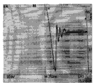
In the application of a high-power current conversion technology, transistors such as IGBT (insulated gate bipolar transistor) and the like have limited capacity of bearing overvoltage and overcurrent, the overcurrent amplitude is usually 2 times of a rated value, and the time of bearing overcurrent is short and is usually only about 1 millisecond; while the IGBT cannot withstand the surge higher than the nominal voltage in terms of withstanding the overvoltage. In order to prevent overvoltage damage of the IGBT device, the wiring inductance parameter of the main circuit connection line should be reduced as much as possible. However, since a single IGBT can provide a limited current capacity (only hundreds of amperes), to provide a larger current rating for the load capability, multiple single IGBTs must actually be used in parallel. Due to the parameter discreteness of the semiconductor device, when the IGBT devices are connected in parallel, unbalanced voltage and unbalanced current can be generated, and overlarge switching peak voltage can be generated due to unreasonable wiring of a main loop to threaten the safety of the IGBT. Referring to fig. 3, it is a waveform photograph of a peak surge voltage (also commonly referred to in the industry as a glitch) occurring when an IGBT device is turned off under a current load condition of about 60% of a rated voltage (about 150V) of a general chopper circuit outputting a rated voltage of 240V recorded by an oscilloscope. The abscissa in fig. 3 represents time, and the ordinate represents voltage amplitude; wherein, in the ordinate direction, each cell represents a voltage amplitude of 50V. As can be seen from fig. 3: the amplitude of the turn-off glitch is large, around 230V, only at about 60% load; as the load current increases, the glitch continues to grow, even beyond the voltage that the IGBT can withstand. Obviously, this threatens the operational safety of the IGBT device.
In order to solve the problem of the excessive amplitude of the glitch, it is a common practice in the industry to use a fast absorption buffer circuit in the load main loop for protection. However, in some applications where the load is often subject to large and frequent changes, for example: high frequency welding, direct current motor speed regulation, etc., which have extremely limited effects. For the above objective reasons, the existing high-power chopper manufactured by using the IGBT often can work when the load is low, and once the load is increased to be close to the rated load, the IGBT device is permanently damaged due to the fact that burrs are too large. Therefore, it is objectively difficult to manufacture a high-power chopper with high reliability using an IGBT. This is also the main reason why the industry has not mass-produced and used high power dc switching power supplies made of IGBT devices so far. For this reason, some research institutes have been specifically discussed in professional technical papers, considering that: in the application occasions of high voltage and large current, the stability of the IGBT module is far less than that of the running state of the silicon controlled rectifier; however, as described above: if the thyristor is used for manufacturing a high-power chopper, adverse effects such as reduction of a power factor and the like are caused. Therefore, it is a continuous object of the industry to solve the problems of operational reliability and safety of the IGBT module.
In the process of making the invention, the inventor finds out through intensive research that: although the circuits shown in fig. 1 and fig. 2 can be realized in principle, it is far from sufficient to satisfy the requirement that the electrical connection is correct, and the reason for many failed chopped wave power supplies is not a circuit design error, but the layout and connection process of the key power components of the main power circuit are not reasonable, which results in the existence of excessive switching glitches and Electromagnetic interference (EMI), and the Electromagnetic Compatibility (EMC) cannot satisfy the requirement.
Referring to fig. 4, in the prior art, when manufacturing the high-power chopper shown in fig. 1 and 2, a plurality of components such as the IGBT module 2, the PWM control circuit board 60, etc. are generally disposed in the switching power supply cabinet 80 in a separated mounting manner based on the general cooling and conducting bus line arrangement requirements; in order to ensure heat dissipation, the IGBT module 2 is usually disposed on a water-cooling plate (not shown); in such layout design, the problems of the glitch, EMI, EMC and the like are not properly considered, and the layout of the power components such as the IGBT module 2 in the switching power supply cabinet 80 is designed in a targeted manner, so that the distribution parameters of the chopper main circuit are deteriorated due to the large stray inductance, the generated glitch is increased along with the increase of the load current, and the safety of the IGBT is threatened.
Disclosure of Invention
One aspect of the invention is to provide an integrated high-power chopper, which has an integrated structure capable of inhibiting switch burrs and electromagnetic interference, and the integrated high-power chopper can integrate a plurality of IGBT modules connected in a series-parallel mode, further improve the output power of the whole chopper, form an integrated component structure convenient to install, inhibit the influence of the electromagnetic interference and the burrs on the IGBT modules by using smaller distributed inductance, and ensure the operation safety of the whole chopper.
In order to achieve the above object, the present invention provides an integrated high-power chopper, which is composed of a plurality of high-power choppers connected in parallel. The high-power chopper is formed by connecting a high-power IGBT module, a filter capacitor and a cooling device. In electrical aspect, the grid of the high-power IGBT module is connected with the PWM control signal of the PWM control circuit board. In the aspect of structure, the high-power IGBT module, the cooling device and the filter capacitor are fixedly and concentratedly arranged in the first box body capable of shielding electromagnetic interference, so that distributed inductance parameters connected with a main circuit are greatly reduced; the PWM control circuit board is arranged in a second box body capable of shielding electromagnetic interference. The first case is provided with a plurality of openings, so that the electrode conductors connected to the output end of the IGBT module can be exposed to the outside of the first case based on the openings, and the electrode conductors can be connected to the dc power input/output cables or terminals of the high-frequency switching power supply. In addition, a pipe joint provided in the cooling device for connecting and transporting the cooling medium is also exposed from the first casing through the aforementioned opening.
Compared with the prior art, the integrated high-power chopper has the advantages that the high-power IGBT module, the cooling device, the filter capacitor and other strong electric components are intensively and fixedly arranged in the first box body capable of shielding electromagnetic interference, and the PWM control circuit board is arranged in the second box body capable of shielding electromagnetic interference. Therefore, on one hand, external electromagnetic interference hardly causes any interference on components and circuits in the first box body and the second box body, so that the electromagnetic interference can be reliably inhibited, the amplitude of burrs is greatly reduced, and the operation safety of the whole chopper is ensured; on the other hand, based on the safe and reliable integrated high-power chopper, a plurality of integrated high-power choppers can be connected together in a parallel and/or series connection mode to form the integrated chopper with larger output power, so that the requirement of a direct-current switch power supply with more than tens of kilowatts can be met, on one hand, the active power of a power supply can not be reduced, and meanwhile, the investment of a power consumption unit due to power compensation can be reduced or even avoided.
Another aspect of the present invention is to provide a high-frequency switching power supply using the above integrated high-power chopper, which is manufactured by using a high-power chopper with an integrated structure, and can safely and effectively provide a high-power dc switching power supply suitable for industrial applications, and at the same time, can improve the active efficiency of the power supply, and save or reduce the capital investment due to reactive power compensation.
To achieve the object of the second aspect of the invention, the invention provides a high-frequency switching power supply of the type comprising the above-mentioned integrated high-power chopper; the power frequency alternating current power supply rectifier comprises an uncontrolled rectifier and a filter circuit, wherein the uncontrolled rectifier is used for rectifying a power frequency alternating current power supply, and the filter circuit is connected with the uncontrolled rectifier; the integrated high-power choppers are multiple and are connected in parallel and/or in series; and the cooling device of the integrated high-power chopper is connected with a cooling medium conveying pipeline.
In view of the advantages of the integrated high-power chopper relative to the prior art, the high-frequency switching power supply can ensure the safe operation; meanwhile, based on the safe and reliable integrated high-power chopper, a plurality of integrated high-power choppers are connected together in a parallel and/or series connection mode, so that a high-frequency switching power supply with larger output power can be obtained, the requirement of a direct-current switching power supply with more than tens of kilowatts can be met, on one hand, the active power of a power supply can not be reduced, and meanwhile, the investment of a power consumption unit due to power compensation can be reduced or even avoided.
In order to facilitate the understanding of the present invention, some embodiments of the present invention will be described in further detail below with reference to several embodiments and the accompanying drawings.
Drawings
FIG. 1 is a schematic diagram of a high power chopper constructed with high power IGBTs;
FIG. 2 is a schematic diagram of a high power chopper constructed by connecting the choppers shown in FIG. 1 in parallel with each other;
FIG. 3 is a waveform photograph of an impulse voltage when a general chopper circuit turns off an IGBT device, which is displayed by an oscilloscope;
FIG. 4 is a schematic diagram of a prior art chopper in a separate arrangement in a power supply cabinet;
FIG. 5 is a schematic diagram of a first housing of the integrated high-power chopper of the present invention;
FIG. 6 is a schematic diagram of a second housing of the integrated high-power chopper of the present invention;
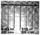
FIG. 7 is a photograph showing the waveform of the chopper output 150V DC voltage according to the first embodiment of the present invention on an oscilloscope;
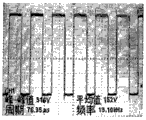
FIG. 8 is a photograph of a waveform of the chopper output 240V DC voltage of the first embodiment of the present invention shown on an oscilloscope;
FIG. 9 is an overall expanded schematic diagram of an integrated high power chopper in another embodiment of the present invention;
FIG. 10 is a schematic diagram reflecting the structural relationship of the main components in FIG. 9;
FIG. 11 is a schematic view of the assembled structure of the internal components of the first casing in FIG. 9;
FIG. 12 is a schematic diagram of the integrated high power chopper of FIG. 9 fully assembled;
FIG. 13 is a schematic diagram of an overall expanded structure of an integrated high power chopper in accordance with yet another embodiment of the present invention;
fig. 14 is a schematic diagram of the complete assembly of the integrated high-power chopper shown in fig. 13.
Detailed Description
Referring to fig. 5 and 6, one class of embodiments of the integrated high-power chopper of the present invention specifically includes: two cases capable of shielding electromagnetic interference, a first case 40 and a second case 41; a plurality of high-power choppers (not shown) connected in parallel with each other are compactly and fixedly arranged in the first box 40, and the high-power choppers are composed of high-power IGBT modules, filter capacitors and cooling devices. A PWM control circuit board 60 for generating a PWM control signal is provided in the second case 41 shown in fig. 6.
Since the electrode conductors 55, 57 connected to the output terminals of the high power IGBT modules mounted on the first case 40 and the electrode conductors 61, 62 connected to the filter capacitors are connected, the pipe connection 48a for connecting the cooling device needs to be exposed from the first case 40 so that these components can be connected to other circuits or cooling medium pipes, and a plurality of openings 40a, 40b are formed in the first case 40.
In addition, in order to reduce distributed inductance, a common terminal between the dc power supply input into the first case and the output of the integrated high-power chopper of the present invention may be connected to the same internal conductor inside the first case, for example: an electrode copper plate; but are connected at both ends of the electrode plate, respectively. Taking this embodiment as an example: assume that the electrode conductor 62 of the filter capacitor is connected to the negative terminal of the input dc power supply and the negative terminal of the output terminal of the high power IGBT module is connected to the electrode conductor 55. Electrode conductors 62, 55 are connected to both ends of the same electrode copper plate inside the first case 40; namely: the common terminals of the dc power supply input and the chopper output are separately connected. By doing so, the peak glitches of the integrated high-power chopper can be greatly reduced.
The electrical connection relationship between the high-power IGBT modules and the PWM control signal is the same as that in the prior art. When the first box 40 and the second box 41 are separately disposed, since the high-power IGBT module and the PWM control circuit board are separately disposed in the first box 40 and the second box 41, which are independent from each other, via holes 40b and 41b are further required to be respectively formed in the first box 40 and the second box 41, so that a wire connecting a gate of the IGBT module and a PWM control signal of the PWM control circuit board passes through the via holes 40b and 41b, and the PWM control signal can be connected to the high-power IGBT module.
In the first box 40 capable of shielding electromagnetic interference, the invention intensively and compactly arranges and constitutes the high-power IGBT module, the filter capacitor and the cooling device. The arrangement structure ensures that the high-power IGBT module can still be sufficiently cooled in the working state of rated power output. At the same time, the most important is that: the IGBT module is isolated from the electromagnetic interference environment generated in the high-frequency switch power supply cabinet body, electromagnetic interference is shielded outside the first box body 40, the structure of chopper distribution parameters is improved, and the amplitude of impulse voltage (burrs) is greatly reduced. In addition, since the PWM control circuit board generating the PWM control signal is disposed in the second case 41 capable of shielding electromagnetic interference, the aforementioned influence of electromagnetic interference on weak points such as the PWM control circuit board is minimized as much as possible.
Referring to fig. 7, it is a photograph of waveforms when the integrated high-power chopper manufactured by the above embodiment of the present invention outputs 150V dc voltage. The 150V dc output voltage is only about 60% of the rated output voltage in the above embodiment. The 150V output voltage was chosen for testing for direct comparison with the aforementioned glitches of the prior art chopper output. As can be seen in fig. 7: and similarly, a direct current voltage of 150V is output, the amplitude of the upper punch burr of the IGBT module of the integrated high-power chopper is only about 20V when the IGBT module is switched on, and the amplitude of the lower punch burr of the IGBT module of the integrated high-power chopper is only about 25V when the IGBT module is switched off. Under the condition of about 60% of rated voltage (about 150V) of a common chopper circuit in the prior art, undershoot burrs during turn-off of the common chopper circuit reach about 230, which is equivalent to about 11 times of the amplitude of the burrs of the integrated high-power chopper. Therefore, compared with the common chopper in the prior art, the high-power chopper manufactured by adopting the integrated structure has very obvious advantages in the aspect of burr suppression.
Please refer to fig. 8, which is a photograph of the waveform of the integrated high-power chopper manufactured by the above-mentioned embodiment of the present invention when outputting 240V dc voltage (full load, i.e. the worst operation condition). As can be seen from the waveforms shown in fig. 8: the upper punch burr of the integrated high-power chopper when the IGBT module is switched on and the lower punch burr of the integrated high-power chopper when the IGBT module is switched off are both about 25V. This indicates that: the main loop distribution parameter (stray inductance) of the integrated high-power chopper is very small, so that burrs are well inhibited.
Reference is made to fig. 9, 10, 11 and 12, which are detailed schematic diagrams of an assembly structure of another embodiment of the integrated high-power chopper of the present invention. The integrated high-power chopper mainly comprises a first box body, a high-power IGBT module 49, a cooling device 48, filter capacitors, electrode conductors 61, 62, 55 and 57, a second box body 45 and the like which are arranged inside the first box body in a tightly assembled mode.
Referring to fig. 9, the first casing 40 is integrally formed of a first casing cover 40x and a bottom plate 46; slide rails 46a and slide rails 40d are provided on the first casing cover 40x and the bottom plate 46, respectively, so that the first casing cover 40x and the bottom plate 46 can be slidably connected to each other by means of the slide rails 46a and the slide rails 40 d.
Referring to fig. 10 and 11, the IGBT module 49, the cooling device 48, the filter capacitor, and the electrode conductors 61, 62, 55, 57 are fixed to the bottom plate 46; the plurality of IGBT modules 49 are fixed in parallel to the cooling device 48, and the heat radiation surfaces of the IGBT modules 49 are bonded to the heat exchange surface of the cooling device 48 to constitute a power unit. Emitters of the plurality of IGBT modules 49 are connected in parallel to each other by copper plates 50, and the copper plates 50 are further connected to electrode conductors 57 via copper plates 58; the electrode conductor 57 is the positive electrode output terminal 6 in the chopper circuit shown in fig. 1. The filter capacitors are connected in parallel by a plurality of capacitors 54; wherein a first electrode of the capacitor 54 is connected to a first conductive plate, i.e. the positive plate 53, and a second electrode of the capacitor 54 is connected to a second conductive plate, i.e. the negative plate 51; an insulating plate 52 is interposed between the positive electrode plate 53 and the negative electrode plate 51 to prevent the positive electrode plate 53 and the negative electrode plate 51 from being short-circuited. The positive and negative electrodes of the dc input power from the uncontrolled rectifier are connected to the positive and negative electrode plates 53 and 51, respectively, by electrode conductors 61 and 62. The negative electrode plate 51 is also connected to an electrode conductor 55, and constitutes a negative electrode of the output of the integrated high-power chopper in the present embodiment. The electrode conductors 61 and 62 are insulated from each other, and a conductive plate 62a is connected to the electrode conductor 62 to connect the negative electrode plate 51 and the electrode conductor 62. The components disposed in the first casing 40 are directly or indirectly fixed to the bottom plate 46, and openings 46b and 46c are further formed in the bottom plate 46 so that the electrode conductors 61, 62, 55, 57 and the pipe connection port 48a for connecting the cooling device can be exposed from the first casing 40. In addition, an insulating plate 63 may be fixed to the bottom plate 46 in order to reinforce a mechanical supporting force for each component provided on the bottom plate 46. To further strengthen the mechanical support for the cooling device 48, a support plate 59 may be added as shown in fig. 10 and 11. Each of the conductive electrodes described above may be formed using a copper plate or a metal or alloy having good conductive properties like copper, silver, or the like.
Referring to fig. 9 and 10, the second casing 41 is integrally formed of a groove-shaped mask 45, a PWM control circuit board 60 is fixedly installed in the groove-shaped mask 45, and a connecting portion 41a for fixing the groove-shaped mask 45 to the first casing cover 40x is further provided on the groove-shaped mask 45.
In the specific installation, the first box housing 40x is usually fixed at a designated position in the power cabinet by the fixing portion 40c on the first box housing 40 x; then, the bottom plate 46, to which the IGBT module 49, the cooling device 48, and the like are fixedly attached, is slidably mounted and fixed in the first casing housing fixed to a predetermined position in the power cabinet via the slide rail 46a and the slide rail 40 d. It should be noted that: the first box housing 40x and the bottom plate 46 can be connected in a snap-fit manner, in addition to the sliding connection manner, i.e., the first box housing 40x and the bottom plate 46 are respectively provided with mutually matched buckles; of course, any other means such as screwing may be selected so as to firmly and integrally connect the first casing cover 40x and the bottom plate 46. Finally, after the PWM control signals of the PWM control circuit board 60 are connected to the respective IGBT modules 49, the second case 41 is fixed to the first case cover via the connecting portion 41a of the second case 41, thereby forming an integrated high-power chopper as shown in fig. 12. Similarly, the groove-shaped cover plate 45 of the first casing cover and the second casing 41 may be fixedly connected by the connection between the first casing cover 40x and the bottom plate 46.
Referring to fig. 10 and 11, a plurality of through holes 51a are provided in a region of the negative electrode plate 51 near the edge of the conductive electrode 55, and cut-off notches 51b are provided outside the through holes 51 a. The provision of these through holes 51a and the opening notches 51b makes the distribution of the current output from the negative electrode plate 51 uniform among the IGBT modules 49, and achieves a good effect of suppressing burrs.
The first casing 40 and the second casing 41, which are capable of shielding electromagnetic interference, should be made of a material with good magnetic conductivity; because steel plate, steel screen, the panel that is equipped with the steel mesh in, alloy plate etc. have good magnetic conduction effect, can be used for making aforementioned first box and second box. In particular, the steel plate and the steel plate mesh belong to materials which are low in price, easy to obtain, process and manufacture and have enough strength, and are particularly suitable for the integrated high-power chopper.
In the above embodiment, the second casing 41 is merely fastened to the first casing cover 40x by using the groove-shaped cover plate 45. This is a relatively simple way of integrally connecting the second casing to the first casing. According to the specific design requirements of the power cabinet and the actual requirements of separating strong current from weak current and the like, the second box body and the first box body can be arranged in a separated mode. Thus, the two cases need to be separately manufactured by using the materials with good magnetic conductivity. They can be formed by a sliding connection or a snap connection, respectively.
Reference is made to fig. 13 and 14, which are an expanded schematic diagram and an assembled schematic diagram of the overall structure of the integrated high-power chopper in another embodiment of the invention. The differences from the integrated high-power chopper shown in fig. 9-12 are: the integrated high-power chopper shown in FIGS. 9-12 is composed of two groups of power units and two groups of filter capacitors, and the integration level is high. In fig. 13 and 14, only one group of power units and one group of filter capacitors are provided, and the structure is relatively simple.
In fig. 13, the filter capacitor and the power unit have substantially the same structures as those of the filter capacitor and the power unit in the embodiments described in fig. 9 to 12. A plurality of IGBT modules 49 are fixed in parallel to the cooling device 48, and the cooling device 48 is provided with a pipe connection 48a through which the first casing is exposed; the heat radiation surface of the IGBT module 49 is bonded to the heat exchange surface of the cooling device 48, thereby constituting a power unit. The emitters of the plurality of IGBT modules 49 are connected in parallel to each other by copper plates 24, and the copper plates 24 are further connected to copper plates 25, forming positive electrode output terminals 6 in the chopper circuit shown in fig. 1. The filter capacitors are connected in parallel by a plurality of capacitors 54; wherein a first electrode of the capacitor 54 is connected to a first conductive plate, i.e. the positive plate 53, and a second electrode of the capacitor 54 is connected to a second conductive plate, i.e. the negative plate 51; an insulating plate 52 is interposed between the positive electrode plate 53 and the negative electrode plate 51 to prevent the positive electrode plate 53 and the negative electrode plate 51 from being short-circuited. Positive and negative electrodes from the non-rectifier dc input power supply are connected to the positive electrode plate 53 and the negative electrode plate 51, respectively. The negative plate 51 is connected to the copper plate 26 to constitute a negative electrode of the output of the integrated high-power chopper in the present embodiment, and the copper plate 25 constitutes a positive electrode of the output of the integrated high-power chopper. Each of the conductive electrodes described above may be formed using a copper plate or a metal or alloy having good conductive properties like copper, silver, or the like.
In the present embodiment, the first casing is formed by connecting the casing end plates 20 and 21 and the holder plates 18 and 19. Insulating plates 22, 23 are installed inside the case end plates 20, 21 to reinforce the mechanical strength between the case end plates 20, 21. The cooling device 48 is provided on the holder plate 18, and a pipe connection 48a for connecting the cooling device is provided on the cooling device 48 and is exposed through the opening 46b in the case end plate 20. The entire first box can be attached and fixed to the power cabinet by means of the bracket plates 18, 19.
The second box 41 of this embodiment is also formed by connecting a trough plate and a cover plate (not shown). The PWM control circuit board 60 is fixedly disposed in the trough plate, and the trough plate has a via hole 41b facing the bottom of the second case, which is used to pass through a wire connecting the gate of the IGBT module 49 and the PWM control signal of the PWM control circuit board 60, thereby ensuring that the PWM control signal can be connected to the high power IGBT module 49. The trough plates can be fixed together by their bottom portions being connected to the end plates 20, 21 of the housing.
The cooling device 48 may be a water-cooled heat sink, or may be a heat sink configured by air cooling or other liquid cooling methods, as long as the corresponding cooling device 48 is suitable for the IGBT module 49 to be attached and configured to radiate heat well.
Each integrated high-power chopper disclosed in each embodiment can intensively arrange the high-power IGBT in the first box 40 capable of shielding electromagnetic interference, and the centralized and compact arrangement constitutes the arrangement structure of the high-power IGBT module, the filter capacitor and the cooling device, so that on one hand, the high-power IGBT module can still be sufficiently cooled in the working state of rated power output, and meanwhile, the IGBT module is isolated from the unavoidable electromagnetic interference environment in the high-frequency switch power supply cabinet body, the electromagnetic interference is shielded outside the first box 40, the structure of chopper distribution parameters is improved, and the amplitude of impulse voltage (glitch) is greatly reduced. In addition, since the PWM control circuit board generating the PWM control signal is disposed in the second case 41 capable of shielding electromagnetic interference, the aforementioned influence of electromagnetic interference on weak points such as the PWM control circuit board is minimized as much as possible. Particularly, as shown in fig. 9-12, the multiple parallel and symmetrical process layouts can ensure the load current balance of each IGBT module, and with such a structure, the distribution parameters can be reduced very low, which is beneficial to the chopper manufactured by the I GBT module to obtain output power of tens of kilowatts to several megawatts, or even higher.
The direct current chopper with load current of hundreds of amperes or even thousands of amperes adopts the independent box type installation structure similar to a frequency converter, and particularly adopts a high-power chopping direct current power supply with multiple IGBT modules connected in parallel, so that the mass and standardized production can be realized, the structure of main elements can be reasonably arranged, the electromagnetic compatibility index can be improved, and the chopper can stably work. In addition, the step-down chopper is manufactured into an integral application component by adopting an integrated design, and the integral application component is taken as an independent unit or a standard component in the electrical cabinet and can conveniently realize the required function by matching with an external connecting wire; the installation and maintenance of the high-power chopper are facilitated, and the overall electromagnetic compatibility and mechanical strength of the switching power supply equipment can be ensured. And the high-power chopper can obtain a full-protection box body and is compact in structure and easy to realize the parallel installation of two ways of single boxes or multiple ways of components at the same time by adopting components similar to a sliding rail, a sliding way and the like and similar to a drawer type component.
Based on the integrated high-power chopper, the invention also can provide a high-power high-frequency switching power supply which is formed by mutually connecting a rectifier and the integrated high-power chopper.
The rectifier is generally mainly composed of a high-power uncontrolled rectifier bridge, the input of which is connected with three-phase power-frequency alternating current, and the output of which is transmitted to the integrated high-power chopper after passing through a filter circuit mainly composed of an inductor. The rectifier and the filter circuit can be implemented by using the prior art, and the present invention will not be described in detail herein.
The integrated high-power chopper is mainly formed by connecting a plurality of IGBT modules in series and/or in parallel, and the whole high-frequency switching power supply can be formed by connecting a plurality of integrated high-power choppers in series and/or in parallel, so that the high-frequency switching power supply with higher output power is formed. Wherein, a plurality of IGBT modules or integrated high-power choppers are connected in series mainly for obtaining higher output voltage; and a plurality of IGBT modules or integrated high-power choppers are connected in parallel, mainly in order to obtain larger output current. Since the cooling devices are provided in the integrated high-power choppers of the present invention, it is also necessary to connect the pipes for supplying the cooling medium to the cooling devices provided in the integrated high-power choppers in the high-frequency switching power supply in order to provide a sufficient cooling effect.
In view of the fact that the integrated high-power chopper can effectively and stably work at rated voltage, the technical scheme provided by the invention can be utilized in the industry to greatly improve the output power of the direct-current high-frequency switching power supply, and meanwhile, the high-frequency switching power supply can stably and reliably run, and the requirements of various corresponding industrial occasions can be met. Meanwhile, the industry can thoroughly get rid of the direct current power supply made of silicon controlled rectifier, avoid the troubles of power factor reduction, power supply pollution and the like, improve the power utilization efficiency and reduce or avoid the investment cost caused by the reduction of the power factor of the compensation power supply.
Claims (10)
1. An integrated high-power chopper comprises a high-power chopper connected with the input end of a direct-current power supply, wherein the high-power chopper consists of a high-power IGBT module, a filter capacitor and a cooling device, and the grid electrode of the high-power IGBT module is connected with a PWM control signal of a PWM control circuit board; the method is characterized in that:
the high-power IGBT module, the cooling device and the filter capacitor are fixedly and intensively arranged in a first box body capable of shielding electromagnetic interference; the PWM control circuit board is arranged in a second box body capable of shielding electromagnetic interference;
the first box body is provided with a plurality of openings, so that the electrode conductor connected with the output end of the IGBT module and the electrode conductor connected with the filter capacitor can be exposed out of the first box body, and a pipeline interface connected with the cooling device and used for conveying a cooling medium is exposed out of the first box body through the openings.
2. The integrated high-power chopper according to claim 1, wherein: the high-power IGBT module is fixedly arranged on the cooling device and forms a power unit with the cooling device.
3. The integrated high-power chopper according to claim 1, wherein: the common end of the direct current power supply input end and the IGBT module output end is arranged in the first box body to be a same inner conductor, and one electrode conductor connected with the IGBT module and one electrode conductor connected with the direct current power supply input end are respectively connected to two ends of the inner conductor.
4. The integrated high-power chopper according to claim 1, wherein: the filter capacitor is formed by connecting a plurality of capacitors in parallel, a first electrode and a second electrode of each capacitor are respectively connected with a first conductive polar plate and a second conductive polar plate, and the first conductive polar plate and the second conductive polar plate are mutually insulated; the electrode conductor of the filter capacitor comprises a first capacitor electrode conductor and a second capacitor electrode conductor, the first capacitor electrode conductor is connected with the first conductive pole plate, and the second capacitor electrode conductor is connected with the second conductive pole plate.
5. The integrated high-power chopper according to claim 4, wherein: the first conductive pole plate or the second conductive pole plate is provided with a plurality of through holes in the area close to the edge, and notches are arranged on the outer sides of the through holes.
6. The integrated high-power chopper according to claim 1, wherein: the first box body capable of shielding electromagnetic interference and/or the second box body capable of shielding electromagnetic interference are/is composed of steel plates with good magnetic conductivity, steel plate meshes, plates with steel meshes arranged inside and/or alloy plates.
7. The integrated high-power chopper according to claim 1 or 6, wherein: the first box body is composed of a first cover body and a first bottom plate, and the first cover body and the first bottom plate are connected in a sliding mode through a sliding rail structure or in a buckling mode through a buckling structure; the high-power IGBT module, the cooling device and the filter capacitor are fixedly arranged on the first bottom plate in a centralized manner; and the first cover body or the first bottom plate is provided with a connecting structure for connecting the first cover body or the first bottom plate to the inside of the power cabinet.
8. The integrated high-power chopper according to claim 1 or 6, wherein: the second box body is composed of a second cover body and a second bottom plate, and the second cover body and the second bottom plate are connected in a sliding mode through a sliding rail structure or in a buckling mode through a buckling structure; the PWM control circuit board is arranged on the second bottom plate; and the second cover body or the second bottom plate is provided with a connecting structure for connecting the second cover body or the second bottom plate to the power cabinet body or the first box body.
9. The integrated high-power chopper according to claim 1, wherein: the second box body is covered on the first box body; or the first box body and the second box body are separately arranged, and a via hole is formed in the first box body and/or the second box body and is used for enabling a lead wire for connecting the grid of the IGBT module and a PWM control signal of the PWM control circuit board to penetrate through.
10. A high frequency switching power supply comprising an integrated high power chopper as claimed in any one of claims 1 to 9; the method comprises the following steps: the uncontrolled rectifier is used for rectifying the power frequency alternating current power supply, and the filter circuit is connected with the uncontrolled rectifier; the method is characterized in that: the integrated high-power choppers are multiple and are connected in parallel and/or in series; and the cooling device of the integrated high-power chopper is connected with a cooling medium conveying pipeline.
Priority Applications (1)
| Application Number | Priority Date | Filing Date | Title |
|---|---|---|---|
| CN2009102606250A CN102104332A (en) | 2009-12-18 | 2009-12-18 | Integrated high-power chopper and high-frequency switch power supply |
Applications Claiming Priority (1)
| Application Number | Priority Date | Filing Date | Title |
|---|---|---|---|
| CN2009102606250A CN102104332A (en) | 2009-12-18 | 2009-12-18 | Integrated high-power chopper and high-frequency switch power supply |
Publications (1)
| Publication Number | Publication Date |
|---|---|
| CN102104332A true CN102104332A (en) | 2011-06-22 |
Family
ID=44156912
Family Applications (1)
| Application Number | Title | Priority Date | Filing Date |
|---|---|---|---|
| CN2009102606250A Pending CN102104332A (en) | 2009-12-18 | 2009-12-18 | Integrated high-power chopper and high-frequency switch power supply |
Country Status (1)
| Country | Link |
|---|---|
| CN (1) | CN102104332A (en) |
Cited By (10)
| Publication number | Priority date | Publication date | Assignee | Title |
|---|---|---|---|---|
| CN102931866A (en) * | 2012-10-24 | 2013-02-13 | 保定红星高频设备有限公司 | Inverter assembly and inverter power supply |
| WO2013060128A1 (en) * | 2011-10-27 | 2013-05-02 | 荣信电力电子股份有限公司 | Multi-unit integrated drawer type power module based on fully-controlled device |
| CN103762883A (en) * | 2014-02-13 | 2014-04-30 | 郭度厚 | Modular high-voltage large-current-pulse power source device |
| CN106685241A (en) * | 2017-01-19 | 2017-05-17 | 河北博宏感应技术股份有限公司 | Novel H-bridge inverter |
| CN106941770A (en) * | 2016-12-07 | 2017-07-11 | 广东文轩热能科技股份有限公司 | A kind of IGBT casings and its assembly method |
| CN109039098A (en) * | 2018-06-07 | 2018-12-18 | 德威(苏州)新能源有限公司 | A kind of efficient energy saving converter device |
| CN109713915A (en) * | 2019-03-07 | 2019-05-03 | 阳光电源股份有限公司 | A kind of electric machine controller |
| CN109842125A (en) * | 2019-03-16 | 2019-06-04 | 盐城工业职业技术学院 | A kind of distribution system optimizing cell power consumption efficiency |
| CN109874259A (en) * | 2017-12-05 | 2019-06-11 | 北京自动化控制设备研究所 | A kind of modularization comprehensive control device assembly method |
| CN112448597A (en) * | 2019-09-03 | 2021-03-05 | 株洲中车时代电气股份有限公司 | Power cell arrangement |
-
2009
- 2009-12-18 CN CN2009102606250A patent/CN102104332A/en active Pending
Cited By (16)
| Publication number | Priority date | Publication date | Assignee | Title |
|---|---|---|---|---|
| WO2013060128A1 (en) * | 2011-10-27 | 2013-05-02 | 荣信电力电子股份有限公司 | Multi-unit integrated drawer type power module based on fully-controlled device |
| CN102931866B (en) * | 2012-10-24 | 2015-06-17 | 保定红星高频设备有限公司 | Inverter assembly and inverter power supply |
| CN102931866A (en) * | 2012-10-24 | 2013-02-13 | 保定红星高频设备有限公司 | Inverter assembly and inverter power supply |
| CN103762883A (en) * | 2014-02-13 | 2014-04-30 | 郭度厚 | Modular high-voltage large-current-pulse power source device |
| CN103762883B (en) * | 2014-02-13 | 2016-06-29 | 郭度厚 | A kind of Modular high-voltage large-current-pulse power source device |
| CN106941770A (en) * | 2016-12-07 | 2017-07-11 | 广东文轩热能科技股份有限公司 | A kind of IGBT casings and its assembly method |
| CN106685241A (en) * | 2017-01-19 | 2017-05-17 | 河北博宏感应技术股份有限公司 | Novel H-bridge inverter |
| CN106685241B (en) * | 2017-01-19 | 2023-04-07 | 河北博宏感应技术股份有限公司 | Novel H-bridge inverter |
| CN109874259B (en) * | 2017-12-05 | 2020-07-21 | 北京自动化控制设备研究所 | Assembly method of modular integrated control device |
| CN109874259A (en) * | 2017-12-05 | 2019-06-11 | 北京自动化控制设备研究所 | A kind of modularization comprehensive control device assembly method |
| CN109039098A (en) * | 2018-06-07 | 2018-12-18 | 德威(苏州)新能源有限公司 | A kind of efficient energy saving converter device |
| CN109713915A (en) * | 2019-03-07 | 2019-05-03 | 阳光电源股份有限公司 | A kind of electric machine controller |
| CN109842125A (en) * | 2019-03-16 | 2019-06-04 | 盐城工业职业技术学院 | A kind of distribution system optimizing cell power consumption efficiency |
| CN109842125B (en) * | 2019-03-16 | 2024-05-10 | 盐城工业职业技术学院 | Power distribution system for optimizing power utilization efficiency of community |
| CN112448597A (en) * | 2019-09-03 | 2021-03-05 | 株洲中车时代电气股份有限公司 | Power cell arrangement |
| CN112448597B (en) * | 2019-09-03 | 2022-03-08 | 株洲中车时代电气股份有限公司 | Power cell arrangement |
Similar Documents
| Publication | Publication Date | Title |
|---|---|---|
| CN102104332A (en) | Integrated high-power chopper and high-frequency switch power supply | |
| Yuan et al. | Opportunities, challenges, and potential solutions in the application of fast-switching SiC power devices and converters | |
| Wang et al. | Overview of silicon carbide technology: Device, converter, system, and application | |
| Teichmann et al. | A comparison of three-level converters versus two-level converters for low-voltage drives, traction, and utility applications | |
| DE112012003135B4 (en) | power converter | |
| US10811958B2 (en) | Water-cooling power supply module | |
| CN104052079A (en) | Electric energy feedback type electronic load | |
| CN110401365B (en) | GaN bridgeless PFC power module for high-power charger | |
| CN101051071A (en) | Multiple input path modular high frequency isolation single phase power feedback type electronic load | |
| CN103036452B (en) | Submodule unit of voltage source transverter based on full control components | |
| US9998028B2 (en) | Low inductivity circuit arrangement of an inverter | |
| Burkard et al. | Paralleling GaN switches for low voltage high current half-bridges | |
| US11990830B2 (en) | Power conversion system and virtual DC voltage generator circuit | |
| CN112787485A (en) | High-frequency DC-DC converter module and auxiliary converter system | |
| Kranzer et al. | Applications of SiC devices | |
| CN103354231B (en) | A kind of IGBT power cell and the submodule for flexible DC power transmission | |
| US10554123B2 (en) | Power converter with a parallel flat plate conductor electrically connected with a capacitor and a power module | |
| EP2858230B1 (en) | Power conversion apparatus | |
| CN201708694U (en) | Integrated high-power choppers and high-frequency switch power supply | |
| KR20160146380A (en) | Power converting apparatus | |
| JP2010161877A (en) | Power conversion device | |
| CN110429850B (en) | High-efficiency GaN three-phase inverter module for new energy power generation system | |
| CN210898534U (en) | Active power filter cabinet body | |
| CN110266179B (en) | Layout method of SiC MOSFET converter and SiC MOSFET converter | |
| CN210007609U (en) | Modular assembly structure of high-power dc-dc converter |
Legal Events
| Date | Code | Title | Description |
|---|---|---|---|
| C06 | Publication | ||
| PB01 | Publication | ||
| C10 | Entry into substantive examination | ||
| SE01 | Entry into force of request for substantive examination | ||
| C12 | Rejection of a patent application after its publication | ||
| RJ01 | Rejection of invention patent application after publication |
Application publication date: 20110622 |