CN102095234A - Solar heat pump and power heat pipe compound system - Google Patents
Solar heat pump and power heat pipe compound system Download PDFInfo
- Publication number
- CN102095234A CN102095234A CN 201110051308 CN201110051308A CN102095234A CN 102095234 A CN102095234 A CN 102095234A CN 201110051308 CN201110051308 CN 201110051308 CN 201110051308 A CN201110051308 A CN 201110051308A CN 102095234 A CN102095234 A CN 102095234A
- Authority
- CN
- China
- Prior art keywords
- heat pipe
- heat
- pipe
- water
- communicated
- Prior art date
- Legal status (The legal status is an assumption and is not a legal conclusion. Google has not performed a legal analysis and makes no representation as to the accuracy of the status listed.)
- Pending
Links
Images
Landscapes
- Heat-Pump Type And Storage Water Heaters (AREA)
Abstract
The invention relates to a solar heat pump and power heat pipe compound system. The system comprises a heat pump system consisting of a compressor, a water-cooling condenser, an evaporator, a throttle mechanism, an indoor air-cooling heat exchanger, an outdoor air-cooling heat exchanger, an electromagnetic valve and a pipeline which are connected with one another; a heat pipe evaporation pipe and a heat pipe return pipe are arranged; one end of the heat pipe evaporation pipe is communicated with an inlet of the water-cooling condenser, and the other end of the heat pipe evaporation pipe is communicated with an outlet of the evaporator; the heat pipe evaporation pipe is provided with the electromagnetic valve; one end of the heat pipe return pipe is communicated with an outlet of the water-cooling condenser, and the other end of the heat pipe return pipe is communicated with an inlet of the evaporator; the heat pipe return pipe is provided with a return medium pump and the electromagnetic valve; and the heat pipe evaporation pipe, the water-cooling condenser, the heat pipe return pipe and the evaporator form an annular power loop. In the system, the solar heat pump is combined with the power heat pipe according to the operation mechanisms of the two, so that various functions are realized through switching between the heat pump and the heat pipe; and the practicability of the system is improved, the conventional energy consumption is reduced, and the comprehensive efficiency of the system is also improved.
Description
Technical field
The invention belongs to the Application of Solar Energy field, relate to the solar heat pump and heat pipe system.
Technical background
Energy problem is the matter of utmost importance that current socio-economic development faces.Energy shortage and efficiency of energy utilization have lowly seriously limited economic development.Solar energy becomes important traditional energy substitute because of the characteristics as regenerative resource and environmental protection.
The solar heat pump technology is a kind of mode of utilizing that solar energy-the Re conversion combines with heat pump circulating system.According to correlative study as can be known, comparing with traditional air-cooled heat pump, is thermal source with solar energy irradiation, and the heat pump performance of heat pump is better.But in the running of solar heat pump, the compression process of compressor need consume more electric energy, and does not need to heat under summer and other hot weathers, only need provide the domestic hot-water.So when solar irradiation preferably the time, passive heat control heat-obtaining water can satisfy the hot water needs, if still adopt solar energy heat pump system to produce the waste that hot water will cause the energy.
Hot pipe technique utilizes the Rapid Thermal hereditary property of heat-conduction principle and refrigeration filling, and working medium is in two-phase section during evaporation, and temperature approaches constant temperature, and heat pipe is a kind of good heat tool for transmitting.Heat pipe and heat pump are combined, not only can provide hot water the whole year, and save energy resource consumption.If the simple gravity assisted heat pipe that uses, efficient obviously can reduce greatly because on-way resistance increases on large-scale loop, and the relative position of the condensation water tank of gravity assisted heat pipe must be to be higher than the evaporimeter position, and is cumbersome in the water tank location arrangement.
Summary of the invention
For solve above-mentioned in heat pipe circuit inefficiency and the condensation water tank relative position problem that is difficult to change, the present invention adopts annular power heat pipe, and combines with solar energy heat pump system and to have proposed a kind of solar heat pump and power heat pipe composite system.
The technical solution that realizes above-mentioned purpose is as follows:
Solar heat pump and power heat pipe composite system comprise the heat pump that compressor, water-cooled condenser, evaporimeter, throttle mechanism, indoor air cooling heat exchanger, outdoor air cooling heat exchanger, magnetic valve and pipeline connect to form; Compressor is communicated with condenser, evaporimeter and throttle mechanism by cross valve; Indoor air cooling heat exchanger in the water-cooled condenser parallel connection, and outdoor air cooling heat exchanger in the evaporimeter parallel connection.
Also comprise heat pipe evaporation tube and heat pipe return duct; One end of heat pipe evaporation tube is being communicated with the water-cooled condenser inlet, and the other end is being communicated with evaporator outlet, and the heat pipe evaporation tube is provided with magnetic valve V8; One end of heat pipe return duct is being communicated with the water-cooled condenser outlet, and the other end is being communicated with evaporator inlet, and the heat pipe return duct is provided with backflow working medium pump 5 and magnetic valve V9; Described heat pipe evaporation tube, water-cooled condenser, heat pipe return duct and evaporimeter looping power loop.
Described evaporimeter is provided with liquid level sensor.
It is last with combining of working medium pump that useful technique effect of the present invention is embodied in heat pipe, by the working medium flow and the heat conduction power of working medium pump adjusting heat pipe, and the efficient of control heat pipe; Owing to there has been working medium pump that power is provided, the position of condensation water tank is just relatively more flexible, and can be placed on needs the local of hot water or other local easily; The power heat pipe can use identical refrigeration working medium with solar heat pump inside.Operation mechanism according to solar heat pump and power heat pipe combines the composition hybrid system with the two, and according to the needs of external condition and heating and refrigeration, switchover operation is realized the application of multiple function between heat pump and heat pipe.Solar heat pump of the present invention and power heat pipe composite system have not only improved the practicality of system, reduce the consumption of conventional energy resource, have also improved the overall efficiency of system.
The method of operation of power heat pipe: liquid working substance absorbs the evaporation of solar energy irradiation in evaporimeter, gas is because the pressure effect enters into water-cooled condenser, in condenser, condense into liquid, drawn back realization circulation in the evaporimeter by working medium pump, liquid level sensor is arranged in the evaporimeter, by the power of liquid level control working medium pump, thus the working medium flow in the control circulation.
The cooling operation mode of solar heat pump: liquid working substance flashes to gas in indoor heat absorption, gas becomes gases at high pressure through compressor compresses, equipressure is condensed into liquid in the gases at high pressure inlet chamber external condenser, and highly pressurised liquid becomes low pressure liquid through choke valve and enters indoor evaporator heat absorption and finish a circulation.
Winter, system switched to the heat pump heating state, was building heating.When solar irradiation was good, the power heat pipe can provide the domestic hot-water separately.Be controlled under the stable duty by working medium pump simultaneously.
Summer, system switched to the heat pump refrigerating state, freezed.When solar irradiation was good, the work of power heat pipe provided the domestic hot-water, was controlled under the stable duty by working medium pump simultaneously.
By the switching between power heat pipe and the solar heat pump, satisfy the demand of people's different times.
The useful technique effect of structure of the present invention embodies in the following areas:
1, on the heat pipe return line, is provided with working medium pump,, can regulates the working medium flow on the heat pipe circuit for the heat pipe circulation provides power.
2, be provided with liquid level sensor in evaporimeter, the power of the control system control working medium pump that sensor connects makes stability of flow.
3, compare with gravity assisted heat pipe, provide power by working medium pump, condensation water tank need not to be placed on relative eminence, can place on demand.
4, be equipped with magnetic valve on the different pipelines of system, control the various functions that different magnetic valves come switched system.
Description of drawings
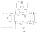
Fig. 1 is the structural representation of system of the present invention.
The specific embodiment
Below in conjunction with accompanying drawing, the present invention is done to describe further by embodiment.
Embodiment:
Referring to Fig. 1, solar heat pump and power heat pipe composite system comprise the heat pump that compressor 1, cross valve 2, water-cooled condenser 3, evaporimeter 4, throttle mechanism, indoor air cooling heat exchanger 6, outdoor air cooling heat exchanger 7, magnetic valve and pipeline connect to form; Compressor 1 is communicated with water-cooled condenser 3, evaporimeter 4 and throttle mechanism by cross valve 2; Water-cooled condenser 3 indoor air cooling heat exchangers 6 in parallel, evaporimeter 4 outdoor air cooling heat exchangers 7 in parallel; The import of water-cooled condenser 3 and outlet are separately installed with condensation import magnetic valve V1 and condensation outlet magnetic valve V5; The import of evaporimeter 4 and outlet are separately installed with evaporation import magnetic valve V3 and evaporation outlet magnetic valve V2; Be separately installed with indoor electric magnet valve V6 and outdoor magnetic valve V7 on indoor air cooling heat exchanger 6 and the outdoor air cooling heat exchanger 7; Be provided with magnetic valve V4 between the outlet of condensation outlet magnetic valve V5 and the evaporation import magnetic valve V3 import.On the evaporimeter 4 liquid level sensor is installed.
Also comprise heat pipe evaporation tube 9 and heat pipe return duct 10; One end of heat pipe evaporation tube 9 is being communicated with water-cooled condenser 3 inlets, and the other end is being communicated with evaporimeter 4 outlets, and magnetic valve V8 is installed on the heat pipe evaporation tube 9; One end of heat pipe return duct 10 is being communicated with water-cooled condenser 3 outlets, and the other end is being communicated with evaporimeter 4 inlets, and backflow working medium pump 5 and magnetic valve V9 are installed on the heat pipe return duct 10.Heat pipe evaporation tube 9, water-cooled condenser 3, heat pipe return duct 10 and evaporimeter 4 looping power loops.
Operation principle of the present invention is as follows:
(1), winter building and heating
The operation of heat pump mode, it is as follows to circulate: compressor 1 → indoor air cooling heat exchanger 6 → choke valve → evaporimeter 4(or outdoor air cooling heat exchanger 7) → and compressor 1, see Fig. 1 hollow core direction of arrow.
(2), produce the domestic hot-water whole year
When solar irradiation was better, with the power heat pipe method of operation, it was as follows to circulate: evaporimeter 4 → heat pipe evaporation tube 9 → water-cooled condenser 3 → heat pipe return duct 10 → evaporimeter 4, see dotted arrow among Fig. 1;
When solar irradiation is bad, use the operation of heat pump mode, it is as follows to circulate: compressor 1 → water-cooled condenser 3 → choke valve → evaporimeter 4(or outdoor air cooling heat exchanger 7) → compressor 1.
(3), the double water that heats of refrigeration in summer
Heat pipe and heat pump move simultaneously, kind of refrigeration cycle: compressor 1 → outdoor air cooling heat exchanger 7 → choke valve → indoor air cooling heat exchanger 6 → compressor 1, see black arrow direction among Fig. 1; The heat control hot water circuit: evaporimeter 4 → heat pipe evaporation tube 9 → water-cooled condenser 3 → heat pipe return duct 10 → evaporimeter 4, see dotted arrow among Fig. 1.
Claims (1)
1. solar heat pump and power heat pipe composite system comprise the heat pump that compressor, water-cooled condenser, evaporimeter, throttle mechanism, indoor air cooling heat exchanger, outdoor air cooling heat exchanger, magnetic valve and pipeline connect to form; Compressor is communicated with condenser, evaporimeter and throttle mechanism by cross valve; Indoor air cooling heat exchanger in the water-cooled condenser parallel connection, and outdoor air cooling heat exchanger in the evaporimeter parallel connection, it is characterized in that:
Also comprise heat pipe evaporation tube and heat pipe return duct; One end of heat pipe evaporation tube is being communicated with the water-cooled condenser inlet, and the other end is being communicated with evaporator outlet, and the heat pipe evaporation tube is provided with magnetic valve (V8); One end of heat pipe return duct is being communicated with the water-cooled condenser outlet, and the other end is being communicated with evaporator inlet, and the heat pipe return duct is provided with backflow working medium pump (5) and magnetic valve (V9); Described heat pipe evaporation tube, water-cooled condenser, heat pipe return duct and evaporimeter looping power loop;
Described evaporimeter is provided with liquid level sensor.
Priority Applications (1)
| Application Number | Priority Date | Filing Date | Title |
|---|---|---|---|
| CN 201110051308 CN102095234A (en) | 2011-03-04 | 2011-03-04 | Solar heat pump and power heat pipe compound system |
Applications Claiming Priority (1)
| Application Number | Priority Date | Filing Date | Title |
|---|---|---|---|
| CN 201110051308 CN102095234A (en) | 2011-03-04 | 2011-03-04 | Solar heat pump and power heat pipe compound system |
Publications (1)
| Publication Number | Publication Date |
|---|---|
| CN102095234A true CN102095234A (en) | 2011-06-15 |
Family
ID=44128430
Family Applications (1)
| Application Number | Title | Priority Date | Filing Date |
|---|---|---|---|
| CN 201110051308 Pending CN102095234A (en) | 2011-03-04 | 2011-03-04 | Solar heat pump and power heat pipe compound system |
Country Status (1)
| Country | Link |
|---|---|
| CN (1) | CN102095234A (en) |
Cited By (5)
| Publication number | Priority date | Publication date | Assignee | Title |
|---|---|---|---|---|
| CN102261711A (en) * | 2011-07-04 | 2011-11-30 | 上海电力学院 | 'Green air-conditioning' operation system |
| CN105042815A (en) * | 2015-07-10 | 2015-11-11 | 安徽建筑大学 | Secondary heat recovery heat-tube type air conditioning system |
| CN107436054A (en) * | 2017-08-25 | 2017-12-05 | 广东美的暖通设备有限公司 | Air source heat pump and its control method |
| CN112066595A (en) * | 2020-09-03 | 2020-12-11 | 万江新能源集团有限公司 | Heat pump host coupling heat pipe system |
| CN114383188A (en) * | 2022-03-24 | 2022-04-22 | 煤炭工业太原设计研究院集团有限公司 | Solar photo-thermal loop heat pipe air-conditioning heating system and control method thereof |
Citations (2)
| Publication number | Priority date | Publication date | Assignee | Title |
|---|---|---|---|---|
| CN101738005A (en) * | 2009-11-13 | 2010-06-16 | 中国科学技术大学 | Solar heat pump and heat pipe composite system |
| CN201983518U (en) * | 2011-03-04 | 2011-09-21 | 中国科学技术大学 | Solar heat pump and dynamic heat pipe compound system |
-
2011
- 2011-03-04 CN CN 201110051308 patent/CN102095234A/en active Pending
Patent Citations (2)
| Publication number | Priority date | Publication date | Assignee | Title |
|---|---|---|---|---|
| CN101738005A (en) * | 2009-11-13 | 2010-06-16 | 中国科学技术大学 | Solar heat pump and heat pipe composite system |
| CN201983518U (en) * | 2011-03-04 | 2011-09-21 | 中国科学技术大学 | Solar heat pump and dynamic heat pipe compound system |
Cited By (5)
| Publication number | Priority date | Publication date | Assignee | Title |
|---|---|---|---|---|
| CN102261711A (en) * | 2011-07-04 | 2011-11-30 | 上海电力学院 | 'Green air-conditioning' operation system |
| CN105042815A (en) * | 2015-07-10 | 2015-11-11 | 安徽建筑大学 | Secondary heat recovery heat-tube type air conditioning system |
| CN107436054A (en) * | 2017-08-25 | 2017-12-05 | 广东美的暖通设备有限公司 | Air source heat pump and its control method |
| CN112066595A (en) * | 2020-09-03 | 2020-12-11 | 万江新能源集团有限公司 | Heat pump host coupling heat pipe system |
| CN114383188A (en) * | 2022-03-24 | 2022-04-22 | 煤炭工业太原设计研究院集团有限公司 | Solar photo-thermal loop heat pipe air-conditioning heating system and control method thereof |
Similar Documents
| Publication | Publication Date | Title |
|---|---|---|
| CN100547319C (en) | List/single/double stage mixed composite stacking heat pump air-conditioning unit | |
| CN101387456B (en) | Cold-warmer bath integrated air source heat pump at cold region | |
| CN100498128C (en) | Low grade energy driven and mechanical power driven composite heat pump, refrigeration system | |
| CN101738005B (en) | Solar heat pump and heat pipe composite system | |
| CN103129348A (en) | Electric vehicle heat pump system | |
| CN105222404A (en) | One utilizes solar energy-air energy heat pump | |
| CN103175324A (en) | Concurrent flow evaporative type condensation refrigerating unit with heat recovery | |
| CN201363859Y (en) | Air conditioning unit | |
| CN201680650U (en) | Multifunctional solar heat pump unit | |
| CN105627623A (en) | Novel solar energy-air energy combined heat pump cold-heat combined supply unit | |
| CN203586629U (en) | Air source heat pump air conditioning unit with multiple switchable heat exchangers | |
| CN102937315A (en) | Refrigeration and cold accumulation system | |
| CN102095234A (en) | Solar heat pump and power heat pipe compound system | |
| CN202885144U (en) | Cooling and heating domestic hot water integrated machine unit combining solar energy and water cooling/air cooling air conditioning unit | |
| CN204240636U (en) | A kind of new type solar energy-air energy combined heat-pump cold and heat combined supply unit | |
| CN201322468Y (en) | Novel multi-functional heat pump air conditioner | |
| CN102980323A (en) | Power heat pipe type central air-conditioner | |
| CN101806515B (en) | High-efficiency hot water tri-generation system for solar air conditioner | |
| CN203785282U (en) | Hot water system of solar combined multiplex heat pump | |
| CN202018156U (en) | Energy-saving heat-pump hot water air conditioner | |
| CN201983518U (en) | Solar heat pump and dynamic heat pipe compound system | |
| WO2021135297A1 (en) | Geothermal-thermoelectrical cooperative air-conditioning system | |
| CN201062893Y (en) | Air-earth energy double heat sources synchronous combined heat pump unit | |
| CN1737452A (en) | Fuel gas wind-cooled heat pump cold/hot water air-conditioner | |
| CN100383475C (en) | Air-conditioning water heater by using composite energy source |
Legal Events
| Date | Code | Title | Description |
|---|---|---|---|
| C06 | Publication | ||
| PB01 | Publication | ||
| C10 | Entry into substantive examination | ||
| SE01 | Entry into force of request for substantive examination | ||
| C12 | Rejection of a patent application after its publication | ||
| RJ01 | Rejection of invention patent application after publication |
Application publication date: 20110615 |