CN102084562B - Control element comprising an installation unit - Google Patents
Control element comprising an installation unit Download PDFInfo
- Publication number
- CN102084562B CN102084562B CN200880130206.9A CN200880130206A CN102084562B CN 102084562 B CN102084562 B CN 102084562B CN 200880130206 A CN200880130206 A CN 200880130206A CN 102084562 B CN102084562 B CN 102084562B
- Authority
- CN
- China
- Prior art keywords
- control element
- snap
- fit
- socket
- control
- Prior art date
- Legal status (The legal status is an assumption and is not a legal conclusion. Google has not performed a legal analysis and makes no representation as to the accuracy of the status listed.)
- Expired - Fee Related
Links
Images


Classifications
-
- H—ELECTRICITY
- H02—GENERATION; CONVERSION OR DISTRIBUTION OF ELECTRIC POWER
- H02B—BOARDS, SUBSTATIONS OR SWITCHING ARRANGEMENTS FOR THE SUPPLY OR DISTRIBUTION OF ELECTRIC POWER
- H02B1/00—Frameworks, boards, panels, desks, casings; Details of substations or switching arrangements
- H02B1/015—Boards, panels, desks; Parts thereof or accessories therefor
- H02B1/04—Mounting thereon of switches or of other devices in general, the switch or device having, or being without, casing
- H02B1/044—Mounting through openings
Abstract
The present invention relates to control element (1) comprising an installation unit (2) which has a front plate (3) and a holding element (4). The control element (1) is characterized by at least one locking element (9) which can be introduced into the holding element (4) through an opening (15) in the front plate (3) so as to lock.
Description
Technical field
The present invention relates to a kind of control element that comprises installation unit, described installation unit has panel and holding element.
Background technology
This class installation unit is applied in by instruction and controls on the machine or electric equipment of control appliance (the instruction control appliance such as button, selector switch etc. to control device generation effect) control.These control appliances are arranged on distribution board, guidance panel, cabinet door or casing cover.Control appliance generally all adopts modular construction; That is control appliance for example, consists of actuator, fixed part (collar nut or sectional fixture) and one or more switch element that is embodied as normally closed switch element or normal open switch element.During installation, be all generally from actuator being penetrated in distribution board Shang aperture above, then with fixed part, fixed from behind.Switch element is to use the element mechanical connections such as screw, grab or lock pin on actuator or fixed part.Between switch element and control device, by binding post, set up electrical connection.
In Secure Application field, for example emergent stopping control appliance, requires to force break contact to produce signal by disconnection.That is to say, when emergent stopping control appliance handled Shi, contact and with it corresponding circuit in closure state.In fault or in emergency circumstances, by hitting, clap the emergent stopping actuator being arranged in before distribution board and disconnect break contact, thereby make equipment or machine proceed to safe condition.But this point is only in the situation that can guarantee that the space configuration between actuator and switch element could realize.When installation exists defect or under strong External Force Acting, may occur the situation that switch element is separated with actuator machinery.Now, emergent stopping commander equipment will no longer work, and that is to say, in emergency circumstances it being handled to Shi, contact will no longer disconnect, thereby also just cannot remove the dangerous condition.This can cause great personnel and equipment damage.Therefore, guarantee that reliable between actuator and switch element is connected most important.
For this reason, DE 37 09 970 C2 have disclosed a kind of shell that can insert distribution board Shang aperture.For this shell is fixed in retention wall, in fringe region, in the sidewall of two positioned opposite, be provided with a plurality of grooves, these grooves are connected with adjacent shells face with its end respectively.The perpendicular retaining element of plugging in a spring clip form in these grooves.The degree of depth of groove equates with the width of this spring clip substantially, and recess width is only slightly larger than the material thickness of spring clip.Groove is positioned at ribs region substantially, thereby has enough materials to be used for accommodating these grooves.The middle lengthwise section of spring clip is vertically positioned at groove, and two outside lengthwise sections protrude from outside adjacent wall, and these lengthwise sections form flexible member and the curved extension of next-door neighbour's retention wall, makes its end once again more or less near side wall of outer shell.
DE 100 34 253 C1 describe a kind of commander equipment being fixed in control panel, an intermediary element of this commander equipment is close to control panel in front by lateral branch fixed bearing element and arranges, its medial branch fixed bearing element stretches into or pass a groove gap on this control panel.Signal transducer is close to medial branch fixed bearing element layout in front by supporting area and runs through in district through intermediary element and control panel at one.For the retainer Ke Cong back side of signal transducer, be attached to control panel, and described in available, run through district and clamped.
DE 43 42 512 A1 disclose a kind of concealed electric mounting box for the electric components such as switch, plug or distributor are carried out to electric installation.This case provides a kind of universal flush mounting box of tightening and/or clamping element just can insert installing hole and be fixed of not needing.On the clear area that this flush mounting box is radially arranged at its oversheath, there are a plurality of supporting members, the free end of these supporting members is convexly curved with one and is connected with the depression bar of tooth portion, wherein, the end face of this depression bar extend to always support edge near.In the sheath segment of an employing inclined design, be provided with a plurality of bases of radially arranging, it is connected with each other that the design that these bases adopt makes the flush mounting box of the adjacent installation of a plurality of needs to pass through an elasticity middleware.Only need by this flush mounting box be pressed into simply installing hole just can to its be fixed and position accurate, in this process, between depression bar and with it adjacent installation hole wall, set up a stable clamped-in style form fit connection.
Summary of the invention
The object of this invention is to provide a kind of installation unit through improving and can realize the singlehanded control element of installing.
Having the control element of feature described in claim 1 is the solution of reaching this object.What dependent claims provided is favourable design and the improvement project that can apply alone or in combination.
The present invention is as follows in order to reach the solution of above-mentioned purpose: a kind of control element that comprises installation unit, described installation unit has panel and holding element, wherein, described control element is preferably designed for electric switch and has at least one snap-fit element, described control element can insert described holding element through the opening on described panel or perforation, and engages with described holding element by described at least one snap-fit element.
Described control element preferably has two snap-fit element made of plastic.When control element is pressed into the preferred cylindrical perforation of described panel vertically, preferably there is flexible edge member and be inserted into described holding element.The snap-fit element that is designed to the plastics wing preferably has a plurality of insertions inclined-plane and inserts sphere.When control element is inserted to panel perforation, these plastics wings are resisted against on the wall of panel perforation.Thereby in the plastics wing, produce thus directed towards panel perforation and control element is fixed on to the stress in panel.
The present invention includes the maximum assembly force that the control element of installation unit requires is 8 to 10 newton.A feature of the present invention is exactly just, and control element is pressed into after panel perforation, applies a clamping force that is enough to whole holding element to be reliably arranged on any one installation site.The feature of this solution is just, according to the concrete tolerance of panel perforation, the plastics wing or ambient temperature, applies maximum 45 newton, minimum 12 newton's clamping force.Even if in the disadvantageous situation of mounting condition, also can realize high functionality like this.
The insertion inclined-plane of snap-fit element of the present invention and insert sphere and have centering function, larger form tolerance fluctuation that can counter plate perforation in conjunction with the flexible lateral of the plastics wing compensates.The described plastics wing also has the effect that accessory is positioned.For this reason, described accessory has a plurality of profile of tooth grooves and can be located with respect to described control element.The realization of this function is without using any accessory.
The material of the plastics wing of the present invention preferably adopts Ultramid A3WG7/PA66 GF35.This is that a kind of glass fibre for industrial products (as gear, solenoid valve casing, cable-pulling chain, motor vehicle fuel distributor and automobile variable speed parts) strengthens heat-proof aging injection molding material.Even if can also applying the plastics wing after repeatedly installing, its ageing-resistant performance is enough to overcome the clamping force of the assembly force of described holding element.The high functionality of the plastics wing of the present invention and process stability contribute to realize automation installation process.
If the shell of described control element is made of plastic, just by the direct injection moulding of the plastics wing on control element.If employing extrusion process, is just pressed on the plastics wing in metal consent.When control element is pressed into accessory, the side of the plastics wing is resisted against on the flank of tooth of accessory.Spacing that so just can 90 ° is carried out the location with respect to commander equipment to accessory, and does not need to use other assemblies.Position choosing is staggered the time, and only need to be rotated further simply accessory just can finally realize engaging on the next position.
Also can in the situation that not adopting retainer, realize within the scope of the present invention the durable installation of blind plug.This class nonfunctional closing cock (funktionsloser Verschlussstopfen) inside can accommodatingly be injected into pattern flexible member.The two ends of this flexible member are formed with jaw.
Below will to other advantages of the present invention and embodiment, describe by embodiment and accompanying drawing.
Accompanying drawing explanation
Fig. 1 is the exploded view that the present invention includes the control element of installation unit;
Fig. 2 is the perspective view of this control element;
Fig. 3 is the profile that described control element includes the front view of snap-fit element of the present invention;
Fig. 4 is the profile that described control element includes the end view of snap-fit element shown in Fig. 3;
Fig. 5 includes the amplification profile of the part of snap-fit element of the present invention in Fig. 3;
Fig. 6 is with the inverted perspective view that is injected into the control element of the pattern plastics wing;
Fig. 7 is the local enlarged perspective of Fig. 6;
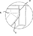
Fig. 8 is the inverted perspective view with the control element of the plug-connected type wing;
Fig. 9 is the local enlarged perspective of Fig. 8;
Figure 10 is the perspective view with accessory control element;
Figure 11 is the bottom view with accessory control element shown in Figure 10;
Figure 12 is the perspective view that is embodied as the control element of nonfunctional closing cock; And
Figure 13 is the bottom view of the nonfunctional closing cock shown in Figure 12.
Embodiment
Fig. 1 is the exploded view that the present invention includes the control element 1 of installation unit 2, and this installation unit has panel 3 and holding element 4.Control element 1 can be embodied as button 5, particularly double-button.Control element 1 preferably has a bipartite shell, and this shell comprises socket 6 and is inserted in the front ring 7 on this socket.Socket 6 has cylinder-shaped body, is embodied as outer casing underpart.Front ring 7 as the shell upper of control element 1 is preferably designed for hyperelliptic shape, because of but the mixture of ellipse and rectangle.Front ring 7 has a bearing-surface 8 that is arranged in its bottom side, and this bearing-surface encircles beyond the socket 6 below 7 in left and right sides projection respectively before being arranged between two parties.In front ring 7, be provided with at least one button 5.Socket 6 is provided with at least one snap-fit element 9.Snap-fit element 9 is preferably designed to wing, have two parallel distributions and respectively with a side 10 that inserts inclined-plane 11 adjacency.These insert fringe region 12 adjacency of inclined-plane 11 and snap-fit element 9.
Fig. 2 is the perspective view of the cylinder-shaped body of control element 1.This main body that is designed to socket 6 preferably has a plurality of wing snap-fit element 9, and these snap-fit element are positioned at 1/3rd of the tops of socket 6, and before next-door neighbour, ring 7 is arranged.The outline of socket 6 adopts Structured Design, that is, in the outer rim of socket 6, both there is even surface 17, be provided with again groove gap 18.Snap-fit element 9 is arranged in of socket 6 and is designed to equally in wing groove 19, and this groove is communicated with guide groove 20.
Fig. 3 is the profile of the cylinder-shaped body of control element 1, wherein includes the front view of snap-fit element 9 of the present invention.Snap-fit element 9 is arranged in the groove 19 of similar shape, and this groove is communicated with guide groove 20.Guide groove 20 consists of two marginal textures 21,22 that are formed on guide groove 20 left and right sides.These marginal textures 21,22 have guide ramp 23 and groove 24, socket 6 orientations can be inserted and are fixed in holding element 4 whereby.
Fig. 4 is the profile of the cylinder-shaped body of control element 1, wherein includes the end view of snap-fit element 9.Except inserting inclined-plane 11, snap-fit element 9 also has can simplify the orientation insertion of socket 6 and the insertion sphere 25 being fixed.
Fig. 5 includes the amplification profile of the part of snap-fit element 9 of the present invention in Fig. 3.In figure, mainly shown the side 10 of this wing snap-fit element and inserted inclined-plane 11.
Fig. 6 is the inverted perspective view (that is, control element 1 is upper, front ring 7 under) with being injected into the control element 1 of the pattern plastics wing, and Fig. 7 is the enlarged drawing of this plastics wing.If socket 6 is made of plastic, just adopt this directly embodiment of the injected-formative plastic wing on socket.
Fig. 8 is that Fig. 9 is the enlarged drawing of this plastics wing with the inverted perspective view of the control element 1 of the compression type plastics wing (that is, control element 1 is upper, front ring 7 under).If socket 6 is to make with metal, just adopt this plastics wing to be pressed on to the embodiment on socket.For snap-fit element 9 being pressed on socket 6, on socket 6, be preferably provided with a dome-shaped protuberance 26.While pressing the compression molding material wing, this protuberance 26 snaps in one and is preferably arranged between two parties in the perforate element 27 on the plastics wing.
Figure 10 is the perspective view with the control element 1 of accessory 28.Figure 11 is the bottom view with the control element 1 of accessory 28.When described control element is pressed into accessory 28, the side 10 of snap-fit element 9 is resisted against on the flank of tooth 29 of accessory 28.These flank of tooth 29 preferably for example, are arranged with prescribed distance (interval is 90 °), in the case, are not needed to use other assemblies location that just spacing is carried out with respect to accessory 28 control element 1 according to the rules.Position choosing is staggered the time, and only need to be rotated further simply accessory 28 just can finally realize engaging on the next position.
Figure 12 is the perspective view that is designed to the control element 1 of nonfunctional closing cock 30.Nonfunctional closing cock 30 (claiming again " blind plug ") inside can accommodatingly be injected into pattern flexible member 31.The outside of the cylinder-shaped body of control element 1 is provided with a plurality of jaws 32 that insert sphere 31 (Figure 13) that have.
Figure 13 is the bottom view of the nonfunctional closing cock 30 shown in Figure 12.
Control element of the present invention has through improved installation unit, by described snap-fit element one hand, can complete installation, very convenient.
Claims (9)
1. a control element that comprises an installation unit, described installation unit has a panel (3) and a holding element (4), it is characterized in that,
Described control element (1) has at least one snap-fit element (9), and can insert described holding element (4) through the perforation of one on described panel (3) (15), and engages with described holding element by described at least one snap-fit element (9),
Wherein, described at least one snap-fit element (9) is arranged in and is designed in wing groove (19), described groove (19) is communicated with guide groove (20), described guide groove (20) consists of two marginal textures (21,22) that are formed on described guide groove (20) left and right sides, and described marginal texture (21,22) has guide ramp (23) and groove (24).
2. control element according to claim 1, is characterized in that,
Described panel (3) by described at least one snap-fit element (9) anti-loose be fixed on described control element (1).
3. control element according to claim 1 and 2, is characterized in that,
Described snap-fit element (9) is made of plastic.
4. control element according to claim 1 and 2, is characterized in that,
Described at least one snap-fit element (9) adopts Flexible Design.
5. control element according to claim 1 and 2, is characterized in that,
Described snap-fit element (9) is designed to include the wing on a plurality of insertions inclined-plane (11).
6. control element according to claim 1 and 2, is characterized in that,
Described snap-fit element (9) has a plurality of insertion spheres (25).
7. control element according to claim 1 and 2, is characterized in that,
Described control element (1) has a front ring (7) and a socket (6), and described at least one snap-fit element (9) injection moulding is on described socket.
8. control element according to claim 1 and 2, is characterized in that,
Described control element (1) has metal consent, and described at least one snap-fit element (9) is pressed in described metal consent.
9. control element according to claim 1, is characterized in that,
Described control element is designed to include the blind plug (30) of socket (6).
Applications Claiming Priority (1)
| Application Number | Priority Date | Filing Date | Title |
|---|---|---|---|
| PCT/EP2008/005780 WO2010006625A1 (en) | 2008-07-15 | 2008-07-15 | Control element comprising an installation unit |
Publications (2)
| Publication Number | Publication Date |
|---|---|
| CN102084562A CN102084562A (en) | 2011-06-01 |
| CN102084562B true CN102084562B (en) | 2014-01-15 |
Family
ID=40473603
Family Applications (1)
| Application Number | Title | Priority Date | Filing Date |
|---|---|---|---|
| CN200880130206.9A Expired - Fee Related CN102084562B (en) | 2008-07-15 | 2008-07-15 | Control element comprising an installation unit |
Country Status (4)
| Country | Link |
|---|---|
| EP (1) | EP2301123B1 (en) |
| CN (1) | CN102084562B (en) |
| BR (1) | BRPI0822941B1 (en) |
| WO (1) | WO2010006625A1 (en) |
Families Citing this family (1)
| Publication number | Priority date | Publication date | Assignee | Title |
|---|---|---|---|---|
| DE102010041041A1 (en) * | 2010-09-20 | 2012-03-22 | Siemens Aktiengesellschaft | Installation unit for fixing emergency stop command-and signaling apparatus i.e. push-button actuator, at front plate in e.g. machine, has connector and terminal device arranged in holder, where terminal device is coordinated with connector |
Citations (5)
| Publication number | Priority date | Publication date | Assignee | Title |
|---|---|---|---|---|
| DE2609473A1 (en) * | 1976-03-08 | 1977-09-15 | Pistor & Kroenert | Signalling light installation mounted on plate - fits into hole in supporting plate with nut on threaded portion |
| EP0037896B1 (en) * | 1980-04-15 | 1985-02-06 | R. Stahl Schaltgeräte GmbH | Switchboard built-in apparatus for mounting through a switchboard aperture |
| US4745534A (en) * | 1986-04-24 | 1988-05-17 | Universo S.A. | Miniature lamp holder |
| US5542859A (en) * | 1994-11-16 | 1996-08-06 | Woods Industries, Inc. | Quick mount electrical wall socket |
| DE10330853A1 (en) * | 2003-07-09 | 2005-02-03 | WEG Indústrias S.A., Jaraguá do Sul | Snap-fit mechanism for securing flange to shaft of control or signal unit using linearly displaced slider for securing shaft inserted in opening of slider |
-
2008
- 2008-07-15 CN CN200880130206.9A patent/CN102084562B/en not_active Expired - Fee Related
- 2008-07-15 BR BRPI0822941A patent/BRPI0822941B1/en not_active IP Right Cessation
- 2008-07-15 WO PCT/EP2008/005780 patent/WO2010006625A1/en active Application Filing
- 2008-07-15 EP EP08784788.5A patent/EP2301123B1/en not_active Not-in-force
Patent Citations (5)
| Publication number | Priority date | Publication date | Assignee | Title |
|---|---|---|---|---|
| DE2609473A1 (en) * | 1976-03-08 | 1977-09-15 | Pistor & Kroenert | Signalling light installation mounted on plate - fits into hole in supporting plate with nut on threaded portion |
| EP0037896B1 (en) * | 1980-04-15 | 1985-02-06 | R. Stahl Schaltgeräte GmbH | Switchboard built-in apparatus for mounting through a switchboard aperture |
| US4745534A (en) * | 1986-04-24 | 1988-05-17 | Universo S.A. | Miniature lamp holder |
| US5542859A (en) * | 1994-11-16 | 1996-08-06 | Woods Industries, Inc. | Quick mount electrical wall socket |
| DE10330853A1 (en) * | 2003-07-09 | 2005-02-03 | WEG Indústrias S.A., Jaraguá do Sul | Snap-fit mechanism for securing flange to shaft of control or signal unit using linearly displaced slider for securing shaft inserted in opening of slider |
Also Published As
| Publication number | Publication date |
|---|---|
| BRPI0822941B1 (en) | 2019-01-22 |
| BRPI0822941A2 (en) | 2018-03-13 |
| EP2301123B1 (en) | 2013-10-02 |
| EP2301123A1 (en) | 2011-03-30 |
| WO2010006625A1 (en) | 2010-01-21 |
| CN102084562A (en) | 2011-06-01 |
Similar Documents
| Publication | Publication Date | Title |
|---|---|---|
| EP2532055B1 (en) | Socket housing | |
| EP1944835B1 (en) | Electrical connection box | |
| US5823807A (en) | Connector assembly with mechanism for confirmation of fitting of connector housing and method of attaching connector housing | |
| US20070141886A1 (en) | Attachment part | |
| KR20060108643A (en) | Housing | |
| US9647371B2 (en) | Multipole electric plug connector part | |
| EP3593417A1 (en) | Electrical plug with specific earthing of outer parts | |
| US9337556B2 (en) | Pump unit with electrical connection plug | |
| CN102084562B (en) | Control element comprising an installation unit | |
| US11611174B2 (en) | Round plug having locking system | |
| JP5346530B2 (en) | Holding frame for connector module | |
| US6765159B1 (en) | Switch to be mounted on a design element in the passenger compartment of a motor vehicle | |
| EP1950844B1 (en) | Divided spring arm | |
| KR20160088863A (en) | Hinge | |
| EP2615697B1 (en) | Lever-fitted connector, and connector unit provided with lever-fitted connector | |
| US20030224638A1 (en) | Terminal protecting cap | |
| EP2409098B1 (en) | Control box arrangement with a mounting element | |
| KR101351519B1 (en) | Cable-clamping device | |
| KR101830415B1 (en) | Connector | |
| CN109314354B (en) | Threading terminal | |
| RU2417476C2 (en) | Switching unit | |
| CN109982534B (en) | Electrical equipment support member for receiving sliding plate | |
| CN210101511U (en) | Mounting assembly, mounting structure and vehicle-mounted electronic device | |
| US9935397B2 (en) | Electrical device and connection arrangement including an electrical device | |
| CN216563581U (en) | Compact screw locking junction box |
Legal Events
| Date | Code | Title | Description |
|---|---|---|---|
| C06 | Publication | ||
| PB01 | Publication | ||
| C10 | Entry into substantive examination | ||
| SE01 | Entry into force of request for substantive examination | ||
| C14 | Grant of patent or utility model | ||
| GR01 | Patent grant | ||
| CF01 | Termination of patent right due to non-payment of annual fee | ||
| CF01 | Termination of patent right due to non-payment of annual fee |
Granted publication date: 20140115 Termination date: 20200715 |