CN102053522B - Electrophotographic image forming apparatus - Google Patents
Electrophotographic image forming apparatus Download PDFInfo
- Publication number
- CN102053522B CN102053522B CN201010529821.6A CN201010529821A CN102053522B CN 102053522 B CN102053522 B CN 102053522B CN 201010529821 A CN201010529821 A CN 201010529821A CN 102053522 B CN102053522 B CN 102053522B
- Authority
- CN
- China
- Prior art keywords
- developing
- image bearing
- bearing member
- drum
- rotary body
- Prior art date
- Legal status (The legal status is an assumption and is not a legal conclusion. Google has not performed a legal analysis and makes no representation as to the accuracy of the status listed.)
- Expired - Fee Related
Links
Images


Classifications
-
- G—PHYSICS
- G03—PHOTOGRAPHY; CINEMATOGRAPHY; ANALOGOUS TECHNIQUES USING WAVES OTHER THAN OPTICAL WAVES; ELECTROGRAPHY; HOLOGRAPHY
- G03G—ELECTROGRAPHY; ELECTROPHOTOGRAPHY; MAGNETOGRAPHY
- G03G21/00—Arrangements not provided for by groups G03G13/00 - G03G19/00, e.g. cleaning, elimination of residual charge
- G03G21/16—Mechanical means for facilitating the maintenance of the apparatus, e.g. modular arrangements
- G03G21/1661—Mechanical means for facilitating the maintenance of the apparatus, e.g. modular arrangements means for handling parts of the apparatus in the apparatus
- G03G21/1676—Mechanical means for facilitating the maintenance of the apparatus, e.g. modular arrangements means for handling parts of the apparatus in the apparatus for the developer unit
-
- G—PHYSICS
- G03—PHOTOGRAPHY; CINEMATOGRAPHY; ANALOGOUS TECHNIQUES USING WAVES OTHER THAN OPTICAL WAVES; ELECTROGRAPHY; HOLOGRAPHY
- G03G—ELECTROGRAPHY; ELECTROPHOTOGRAPHY; MAGNETOGRAPHY
- G03G2221/00—Processes not provided for by group G03G2215/00, e.g. cleaning or residual charge elimination
- G03G2221/16—Mechanical means for facilitating the maintenance of the apparatus, e.g. modular arrangements and complete machine concepts
- G03G2221/1606—Mechanical means for facilitating the maintenance of the apparatus, e.g. modular arrangements and complete machine concepts for the photosensitive element
-
- G—PHYSICS
- G03—PHOTOGRAPHY; CINEMATOGRAPHY; ANALOGOUS TECHNIQUES USING WAVES OTHER THAN OPTICAL WAVES; ELECTROGRAPHY; HOLOGRAPHY
- G03G—ELECTROGRAPHY; ELECTROPHOTOGRAPHY; MAGNETOGRAPHY
- G03G2221/00—Processes not provided for by group G03G2215/00, e.g. cleaning or residual charge elimination
- G03G2221/16—Mechanical means for facilitating the maintenance of the apparatus, e.g. modular arrangements and complete machine concepts
- G03G2221/163—Mechanical means for facilitating the maintenance of the apparatus, e.g. modular arrangements and complete machine concepts for the developer unit
Abstract
An electrophotographic image forming apparatus for forming an image on a recording material, includes (i) a drum cartridge including an image bearing member and charging device for charging a surface of the image bearing member, the drum cartridge being demountably mounted to a main assembly of the electrophotographic image forming apparatus; (ii) a rotary supporting a plurality of developing device each having a developer carrying member for developing an electrostatic latent image formed on the image bearing member, the rotary being swingably mounted to the main assembly of the apparatus through a supporting member and being rotatable, relative to the supporting member, to bring the developing device to a developing position for developing the electrostatic latent image; (iii) a spacer member for spacing between the charging device and the surface of the image bearing member, the spacer member being mounted between the image bearing member and the charging device; and (iv) a locking member for spacing between the developing device positioned in the developing position and the image bearing member, the locking member being demountably mounted between the drum cartridge and the rotary, and the locking member being is provided with a guide portion for guiding the spacer member between the image bearing member and the charging device.
Description
Technical field
The present invention relates to the electrophotographic imaging forming apparatus of the rotary body (rotatable motion) that comprises bulging box, a plurality of developing apparatus and comprise a plurality of mounting portions that to carry developing apparatus.The present invention is particularly suitable for for form the color electrophotographic image forming apparatus of coloured image on recording materials.Here, electrophotographic imaging forming apparatus utilizes electrophotographic image forming method to form image on recording materials.For example, it comprises electrophotographic copier, electrophotographic printer (LED printer, laser beam printer etc.), electrophotographic printer type facsimile recorder and electrophotographic printer type word processor etc.Delevoping cartridge is to comprise box be used to the developer-accommodating of the developer bearing part that makes the latent electrostatic image developing that forms on image bearing member and receiving photographic developer part as the unit.Known developer bearing part is developer roll.In addition, the drum box is to comprise at least the box of charging device and image bearing member as the unit, and this box can removably be installed with respect to the device master component of electrophotographic imaging forming apparatus.
Background technology
In the electrophotographic imaging forming apparatus (imaging device or device) such as duplicating machine, Printers and Faxes machine, the electrostatic latent image that forms on image bearing member develops to visual toner image by developing apparatus.As everyone knows, in color electrophotographic image forming apparatus, rotary body is set as rotatable developing apparatus travel mechanism in master component at device.Four Delevoping cartridges as the developing apparatus that comprises different color developers are releasably attached on rotary body.Rotary body can be arranged on swinging in the contacted direction of the developer roll developing location relative with electrophotographic photosensitive member with electrophotographic photosensitive member (drum) as image bearing member as the developer roll of developer bearing part in Delevoping cartridge along making.The drum box comprises the bulging box framework of support drum and is used for making the charging device of bulging surface charging.In the example of the charging device that is used for imaging device, there is the contact electrification type charging device that is used for making bulging surface charging under charging device and the bulging state that contacts.For example, as the Surface Contact of the charging roller of charging device and drum so that the surface charging of drum.In order to keep in touch with drum, charging roller is pressed towards under bulging state at it and is supported by the drum box framework.But, when the contact between long-term maintenance charging roller and drum, have the tendency of charging roller distortion.In order to address this is that, Japanese laid-open patent application 2000-181328 proposes, and when described bulging box is not used, particularly in the bulging box transportation before the drum box arrives the user, makes charging roller and drum keep being separated from each other.In Japanese laid-open patent application 2000-181328, the distance member that passes bulging coating member and lock this drum coating member with respect to the drum box is set, this distance member is inserted between charging roller and drum.Like this, charging roller and drum keep being separated from each other in the shipment of rousing box and transportation.
Recently, in order to improve availability, imaging device is shipped and transports under drum box and Delevoping cartridge (developing apparatus) are installed to state on the device master component.Then, the user can be in the situation that bring into use imaging device in not taking out bulging box and Delevoping cartridge and installing them into imaging device.In this case, rotary body can be swingingly supported by the master component of device, and therefore, the impact in transportation can cause the collision of other parts in master component with device.
Summary of the invention
Therefore, the purpose of this invention is to provide the imaging device that encapsulates together with drum box and developing apparatus, wherein, prevent that the rotary body that supports developing apparatus from swinging in the processes such as transportation.
Another object of the present invention is, the imaging device that encapsulates together with the bulging box that comprises charging device is provided, and wherein, the distortion of charging device is attributable to it for the press contacts of image bearing member.Another object of the present invention is, provides at an easy rate from the locking that is used for preventing oscillating motion to discharge rotary body and at an easy rate from the imaging device of the locking released development agent load bearing component that is used for preventing contacting with image bearing member.
According to an aspect of the present invention, provide a kind of for form the electrophotographic imaging forming apparatus of image on recording materials, described device comprises: (i) comprise image bearing member and be used for bulging box to the charging device of the surface charging of described image bearing member, described bulging box quilt can be installed on the master component of described electrophotographic imaging forming apparatus with dismantling; Support the rotary body of a plurality of developing apparatuss, each described developing apparatus has be used to the developer bearing part that makes the latent electrostatic image developing that forms on described image bearing member, described rotary body can swingingly be installed on the described master component of described device by support component, and can rotate that with respect to described support component described developing apparatus is taken to be used to the developing location that makes latent electrostatic image developing; (iii) for the isolated distance member on the surface that makes described charging device and described image bearing member, described distance member is installed between described image bearing member and described charging device; (iv) be used for making described image bearing member and the isolated Lock Part that is positioned at the described developing apparatus of described developing location, described Lock Part can be arranged between described bulging box and described rotary body with dismantling, and, described Lock Part is provided with leader, and described leader is used for described distance member is directed between described image bearing member and described charging device.
Description of drawings
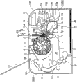
Figure 1A is the schematic cross sectional views of the imaging device according to an embodiment of the invention in holding state, and Figure 1B is the schematic cross sectional views of imaging device, and wherein, Y color development box is moved to developing location.
Fig. 2 A is the schematic cross sectional views of the imaging device of B color development box when being moved to developing location, but Fig. 2 B is the skeleton view of the outward appearance of rotary body, separating component and attachment.
Fig. 3 illustrates Delevoping cartridge.
Fig. 4 illustrates bulging box.
Fig. 5 A illustrates the installation and removal mode of operation of bulging box, and Fig. 5 B is the part enlarged drawing of Fig. 5 A.
Fig. 6 A is the schematic cross sectional views that the imaging device under the state of separating component and Lock Part is installed, and Fig. 6 B is the part enlarged drawing of Fig. 6 A.
Fig. 7 A illustrates the mounting means of Lock Part, and Fig. 7 B is the part enlarged drawing of Fig. 7 A.
Fig. 8 A illustrates the mounting means of distance member, and Fig. 8 B is the part enlarged drawing of Fig. 8 A.
Fig. 9 A is the diagram that the dismounting mode of Lock Part and distance member is shown, and Fig. 9 B is the part enlarged drawing of Fig. 9 A.
Embodiment
(embodiment)
(the general layout of electrophotographic imaging forming apparatus)
With reference to Figure 1A, Figure 1B, Fig. 2 A and Fig. 2 B, structure and the imaging operation of electrophotographic imaging forming apparatus 100 are according to an embodiment of the invention described.Device 100 is the laser beam printers that use electrophotographic method and can form full-colour image (four kinds of colors).Its response is input to the electrical picture signal of control circuit part (not shown) and carries out the colour imaging operation at the recording materials 40 of sheet-form from the host apparatus (not shown) such as personal computer, cis or another facsimile recorder etc.Recording materials 40 are recording materials, sheet material, OHT sheet material or label etc.Control circuit part (control device: CPU) supply with and receive various telecommunications breaths between host apparatus and operation part (not shown), and, in addition, according to comprehensive control of the imaging operation of the implement devices 100 such as predetermined control program and master meter.Therefore, this imaging operation of device 100 described below is partly controlled by control circuit.The device 100 drum type electrophotographic photosensitive members (drum) 71 that comprise as image bearing member.Around drum 71, be provided for making the surface uniform charging of drum 71 charging device 73, be used for utilizing laser beam lithography to form exposure device 15, the developing device 50 of electrostatic latent image by the surface with drum 71.Developing device 50 comprises for make the visual a plurality of developing apparatuss 5 of electrostatic latent image (5a, 5b, 5c, 5d), the conduct that form on drum 71 have the rotary body 1 for the rotatable motion of a plurality of mounting portions of carrying developing apparatus 5 with developer (toner).Be provided for removing from drum 71 cleaning device 72 of remaining toner.Developing device 50 in the present embodiment comprises four developing apparatuss, that is, and and yellow developer 5a, magenta developer 5b, cyan developer 5c and black toner developer 5d.Below, yellow, magenta, cyan and black are expressed as respectively Y color, M color, C color and B color.In the present embodiment, the bulging box 70 on the integrated predetermined mounting portion 100B that forms the master component 100A that can be releasably attached to device 100 of drum 71, charging device 73 and cleaning device 72.Here, the master component 100A of device is the structure of the imaging device 100 except drum box 70.Developer 5 is rotated body 1 and supports, described rotary body 1 can pass through support component 102L, 102R (Fig. 2 B) with respect to device frame 101 swings of the master component 100A of device, and can rotate with respect to support component 102L, 102R, and, around the circumferencial direction configuration developer 5 of rotary body.Developer 5 can be fixed on rotary body 1, perhaps, can be can be from the Delevoping cartridge type of rotary body 1 dismounting.In the situation that static type, the developer-accommodating from developer replenishing part (not shown) to developer is partly supplied with toner.In the present embodiment, use the Delevoping cartridge type.In this case, when display part (not shown) indication toner is empty, change this Delevoping cartridge with new Delevoping cartridge.Below, developer 5a, 5b, 5c, 5d are called as respectively Y color development box 5a, M color development box 5b, C color development box 5c and B color development box 5d.In the installation and removal process of developer 5 with respect to rotary body 1, in the present embodiment, as shown in Fig. 7 A, the upper lid of the upper surface of the master component 100A of device (installation and removal lid) 13 is opened around hinge fraction 13a, with the opening 104 of the master component 100A that opens wide device.By means of installation and removal guide member 14, by opening 104, via predetermined operating process, with respect to rotary body 1 each Delevoping cartridge 5 of installation and removal.Below rotary body 1, intermediate transfer belt unit 30 is set.In the master component 100A of device, intermediate transfer belt unit 30 comprises rear side secondary transfer printing opposed roller 31, protecgulum 25 side drive rollers 32, jockey pulley 33, primary transfer roller 4 and the annular intermediate transfer belt 3 with flexibility that stretches around these rollers.Primary transfer roller 4 is pushed to the lower surface of drum 71, and intermediate transfer belt (band) 3 is therebetween simultaneously.Below intermediate transfer belt unit 30, the box 7 that holds recording materials 40 (sheet material) is set.From installed in front and the dismounting box 7 that protecgulum 25 is set.
Colour imaging operation on recording materials 40 is as follows.The holding state of Figure 1A indication device 100.Control circuit part (not shown) make drum 71 with 3 along the rotary synchronous ground of arrow A direction along the arrow B direction rotation.With 3 and the tip (circumferential) velocity (speed) of drum 71 substantially the same.The surface of drum 71 is predetermined polarity by charging device 73 uniform charging, and by the light exposure corresponding with the Y color component images of color image information.Like this, form the electrostatic latent image corresponding with the Y color component images on drum 71.Synchronize with the formation of electrostatic latent image, rotary body 1 rotates in the direction of arrow C around turning axle or rotation 1a under swing pinion 17 effects.The rotation of rotary body 1 stops at the position that makes Y color development box 5a arrive the developing location X relative with drum 71 of the Y color development box 5a shown in Figure 1B.In this state, as the developer roll 51 of the developer bearing part of Y color development box 5a and toner supplying roller 52 rotations of presenting parts as the developer of developer roll 51, and, supply with predetermined development bias voltages to developer roll 51.By doing like this, provide electric potential difference between drum 71 and developer roll 51, make Y color toner be deposited on the electrostatic latent image that forms on drum 71.Therefore, Y color toner is deposited on electrostatic latent image molded on drum 71, that is, electrostatic latent image is developed.In other words, form Y color toner image on drum 71.Primary transfer roller 4 is supplied to the predetermined primary transfer bias voltage of the opposite polarity of polarity and toner.By doing like this, Y color toner image by primary transfer successively to being with on 3.When completing by this way the primary transfer of Y color toner image on being transferred to 3 from drum 71, control circuit part is rotated rotary body 1 in the direction of arrow C, and successively M color, C color and B color development box 5b, 5c, 5d is taken to their developing location Xs relative with drum 71.Similar with the situation of Y color component images, carry out successively the formation, development of electrostatic latent image and to the primary transfer on 3.Like this, utilize that overlapping Y, M, C, B four colour toners images form the color toner images on 3.During the synthetic formation cycle of the color toner image on 3, as the solid line in Fig. 1 represents, by remain on 3 secondary transfer roller 6 of pushing transfer printing opposed roller 31 to it with 3 off positions that separate.As the solid line in Fig. 1 represents, cleaning unit 10 also be in it with 3 off positions that separate.
On the other hand, control circuit part regularly drives feed roller 8 in predetermined control, 9 to separate and to present recording materials 40 from box 7 to alignment roller.As shown in Fig. 2 A, secondary transfer roller 6 enter that secondary transfer roller 6 is pushed to secondary transfer printing opposed roller 31 so that with 3 with the operating position of secondary transfer printing opposed roller 31 press contacts.Alignment roller 9 is fed to recording materials 40 by secondary transfer roller 6 with the 3 secondary transfer printing pressing sections that form, and secondary transfer roller 6 is supplied to the secondary transfer printing bias voltage of the opposite polarity with predetermined voltage and polarity and toner.Like this, the synthetic color toner image that forms by transfer printing together (secondary transfer printing) to being with on 3.From secondary transfer printing pressing section recording materials 40 out be with 3 to separate, and be fed to fuser 11.In fuser 11, to recording materials 40 apply heat and pressure with fusing toner image on recording materials.By this way, form full-colour image on recording materials.Recording materials 40 are discharged to sheet material discharge section 12.When the tail end of recording materials 40 passed secondary transfer printing pressing section, secondary transfer roller 6 returned to off position and remains there.Arrive secondary transfer printing pressing section with the fore-end of recording materials 40 and synchronize, cleaning unit 10 moves to it and acts on operating position with 3.Like this, utilize cleaning unit 10 to remove not to be transferred to residuing in the transfer printing toner not of the secondary on 3 on recording materials 40.And when the tail end of recording materials 40 passed secondary transfer printing pressing section, cleaning unit 10 returned to off position and remains there.The formation order of the color toner image on drum 71 is not limited to above-mentioned order.Can implement monochrome image forms.
(rotary body)
With reference to Fig. 2 B, the structure of rotary body 1 is according to an embodiment of the invention described.Rotary body 1 comprises the turning axle 1a that stretches along left and right directions and is set to one heart and integrally a pair of dish (left plate and right plate) 34L, 34R on axle on left side and right side.Here, the left side and the right are based on the direction of (protecgulum 25 sides) finder 100 from the front side.Each in the inside surface of left dish and right dish 34L, 34R is provided with mounting portion (four mounting portions altogether) along the dish circumference, and the longitudinal end of Delevoping cartridge 5a, 5b, 5c and 5d is realized removably supporting in the mounting portion.Between the left plate and right plate of device frame 101 of the master component 100A of device, driving shaft 18 is rotatably supported by the parts of bearings (not shown).The left part of driving shaft 18 and right part are provided with respectively support component 102L, 102R.Turning axle 1a is rotatably supported between support component 102L, 102R, and like this, rotary body 1 is supported.Delevoping cartridge 5a, 5b, 5c, 5d can be installed to the precalculated position between dish 34L, 34R with dismantling, make them be set up with the form that roughly is cylinder in concentric mode.The periphery of dish 34L, 34R forms respectively rotary body gear G2L, G2R.The left part of driving shaft 18 and right part are provided with each driven wheel G1L, the G1R that is fixed to the upper.The gear G2L engagement of turning of left side driven wheel G1L and left side spin, and right side driven wheel G1R and right side rotary body gear G2R mesh.The driver M rotation of driving shaft 18 by partly being controlled by control circuit.Utilize this structure, when driving shaft 18 was driven by driver M along predetermined direction, the revolving force of driving shaft 18 was passed to rotary body gear G2L, G2R by driven wheel G1L, G1R.Like this, rotary body 1 rotates around turning axle 1a along being rotated in the forward direction C.Control circuit is partly controlled driver M, thereby with predetermined angle rotation rotary body 1.Because rotary body 1 is suspended in midair by left and right support component 102L, 102R, so rotary body 1 can rotate around driving shaft 18 along the counter clockwise direction that is represented by arrow H and by the clockwise direction that arrow F represents.The swing of H is towards drum 71 in the counterclockwise direction for rotary body 1, and the swing of F is away from drum 71 along clockwise direction.Usually push rotary body 1 around driving shaft 18 along the counter clockwise direction that is represented by arrow H.By this pushing, the developer roll of the calibration rotation by rotary body 1 and the Delevoping cartridge that moves to developing location X can with drum 71 uniform contact.That is, developer roll contacts with drum 71 with predetermined pressure.With rotary body gear G2L, G2R the engagement driven wheel G1L, G1R with concentric as the driving shaft 18 of rotary body 1 oscillating motion axle.Therefore, the pivoting action of rotary body 1 does not cause being disengaged from rotary body gear G2L, G2R.Be used for box mounting portion installation and removal Delevoping cartridge 5a, 5b, the 5c with respect to rotary body 1, the structure of 5d can be used known structure, therefore, its detailed description is omitted.
(Delevoping cartridge)
The structure of Delevoping cartridge 5a, 5b, 5c, 5d is identical.Therefore, the structure of Delevoping cartridge is described with reference to the Y color development box 5a of the present embodiment.The part of Fig. 3 (a) and part (b) are the cut-open views of Delevoping cartridge 5a.Developer container 55 vertically is divided into toner accommodating chamber 56 by toner supply opening 58 and comprises the developer chamber 57 of developer roll 51 and toner supplying roller 52.In unused state before Delevoping cartridge 5a arrives the user, as shown in Fig. 3 (a), the toner seal 59 of form membrane is fixed on developer container 55 with sealing toner supply opening 58 by methods such as welding, makes thus between toner accommodating chamber 56 and developer chamber 57 and separates.By removing toner seal 59 before bringing into use, toner 60 56 falls into developer chamber 57 at the Delevoping cartridge 5a developing location X relative with drum 71 from the toner accommodating chamber.Toner 60 is fed into toner supplying roller 52 from developer chamber 57.Roller 52 rotates that along the clockwise direction that is represented by arrow P toner 60 is supplied to developer roll 51, and from roller 51 scraping toners.Roller 51 comprises the elastic caoutchouc roller, and along the clockwise direction rotation that is represented by arrow Q, and the toner 60 on roller 51 is regulated by developing blade 53, and then is fed into drum 71 at developing location X, so that latent electrostatic image developing.Utilize roller 52 to remove the toner 60 that residues on roller 51 after developing in contact slide part between roller 51 and roller 52.Then, supply with toner by roller 52 to roller 51.For developer roll 51 is stably contacted with drum 71 at developing location X, keep the whole rotary body 1 of Delevoping cartridge 5a to be urged to drum 71 (direction H, Fig. 4).By doing like this, the developer roll 51 of Delevoping cartridge 5a contacts with drum 71 under predetermined pressure.
(drum box)
With reference to Fig. 4, drum box 70 will be described.The part of Fig. 4 (a) is the skeleton view according to the outward appearance of the bulging box 70 of embodiment, (b) is its cut-open view, is (c) skeleton view of charging device 73.Drum box 70 comprises drum 71, charging device 73 and cleaning device 72 as the unit, and can be disassembled (can removably be installed) with respect to the predetermined mounting portion 100B (Fig. 1) of the master component 100A that installs.Drum box 70 is located in and remains on the precalculated position of master component 100A of device.As the preparation that forms electrostatic latent image, charging device 73 makes drum 71 uniform charging to predetermined polarity and electromotive force.Cleaning device 72 is removed the toner of not transfer printing from drum 71, and the toner container of removing is contained in bulging box framework (cleaner container) 76.With reference to (b) of Fig. 4 and (c), the structure of charging device 73 will be described.In the present embodiment, charging device 73 is charging roller type (contact chargings).The below will describe the charging roller as charging device 73.Charging roller 73 comprises rubber rollers part 73a and stiff shaft 73b, and wherein, stiff shaft 73b axially runs through rubber rollers part 73a along drum 71, and its opposite end section forms outstanding outshot 73b1 and 73b2 from rubber rollers part 73a.Charging roller bearing 74 is installed on framework 76, makes the center of charging roller 73 to move on the line Ga-Gb through the center O 71 of the center O 73 of charging roller 73 and drum 71.The outshot 73b1 of charging roller 73 is rotatably by the direction along arrow G, and the bearing 74 that namely extends towards drum 71 supports.Outshot 73b2 also utilizes similar structure to press to drum 71.
The left end of the turning axle 71a of drum 71 and right-hand member rotatably support by left and right bearing 77L, 77R between the left side plate of framework 76. Bearing 77L, 77R outwards give prominence to and are used as from side plate the part that will be positioned.The outside surface of each in the side plate of framework 76 is provided with on symmetric position as outstanding 78L, the 78R that will be directed part.Outstanding 78L, 78R are installed to the downstream that installation direction on the master component 100A of device is arranged on will be positioned part 77L, 77R with respect to drum box 70.In bulging box mounting portion 100B in the master component 100A of device, in order to mount and dismount bulging box, each of the inside surface of the side plate of device frame 101 is provided with for the guide member 19 that supports and guide drum box 70.Each in left and right guide member 19 is provided with the first guiding groove part 19a that can engage with will be positioned part 77L, the 77R of drum box 70 and the second guiding groove part 19b that can engage with outstanding 78L, 78R.The first guiding groove part 19a and the second guiding groove part 19b extend to rotary body 1 from the front openings 105 of the master component 100A of device.The rotary body side end of the first guiding groove part 19a of each in guide member 19 is provided with the depression 19c as localization part.Drum box 70 is pressed by be urged parts 23 under will be positioned part 77L, 77R and state that depression 19c engages, keeps locating with respect to the master component 100A that installs.In the bulging box 70 shown in Figure 1A, Figure 1B, Fig. 2 A and Fig. 2 B was installed to state on the mounting portion 100B of master component 100A of device, drum box 70 was by being positioned part 77L, 77R and will to be directed part 78L, 78R supported between left and right guide member 19.Will be positioned part 77L, the 77R of drum box 70 engage with depression 19c as the localization part of the first guiding groove part 19a.Therefore, utilize push part 23 pushing drum boxes 70 to keep being positioned with respect to the master component 100A of device.Push part 23 is symmetricly set on respectively on left and right leader 19.By be arranged on turning axle 23c as the spring (not shown) of the push part described push part 23 of direction pushing along arrow S.By doing like this, the pushes against surface 23a of push part 23 contacts with the surperficial 76a that will be touched of the left and right sides of the upper surface portion of the framework 76 that is arranged on bulging box 70, with the direction pushing drum box 70 along arrow R.The direction of arrow R is so that the direction of will be positioned part 77L, 77R and depression 19c press contacts around outstanding 78L, 78R going barrel box 70.Under this state, drum box 70 keeps being located in preposition with respect to the master component 100A of device, and in this position, primary transfer roller 4 is by being with 3 to drum 71 press contacts.
In the time will taking out the bulging box 70 of installing from the master component 100A of device, protecgulum 25 rotates so that the front openings 105 of the master component 100A of device is opened around hinge fraction 25a.When protecgulum 25 is opened, keep its open state by ratchet shut-down mechanism (not shown).Then, can see bulging box mounting portion 100B in the master component 100A of auto levelizer by opening 105.The user passes through in the master component 100A of opening 105 with his or her hand insertion apparatus, and distinguishes manual rotation lever 24 around turning axle 24b along arrow K direction, and described lever 24 is symmetricly set on left side and the right side of mounting portion 100B.Fig. 5 B is the part enlarged drawing of Fig. 5 A.Rotation by lever 24, the surface in contact 24aa of lever arm part 24a contacts with the second surface 23bb that will be touched of outstanding 23b on being arranged on push part 23, and push part 23 opposings are rotated around axle 23b along the direction of arrow U as the pushing force of the spring of above-mentioned push part.Like this, pushes against surface 23a moves along the direction of arrow T, makes the pushing of 23 pairs of bulging boxes 70 of left and right push part be released.In other words, will be positioned part 77L, the 77R that rouse box 70 are released crowded the pushing away of localization part 19c of the master component 100A of device.During along the direction rotation of arrow K to predetermined latched position, the locking mechanism (not shown) is operating as and is fixed to latched position, therefore, even lever 24 gains freedom, does not also return when lever 24.Therefore, push part 23 remains on the non-pushing state that does not push bulging box 70.Then, drum box 70 namely is pulled towards front openings 105 by promptly and along the direction of arrow N.Like this, the part that be positioned 77L, 77R and will be directed part 78L, 78R and 105 slide along the first guiding groove part 19a and the second guiding groove part 19b to opening like this, take out drum box 70 by opening 105 from the master component 100A of device.When drum box 70 is installed, drum box 70 is passed through in the master component 100A of opening 105 insertion apparatus along the direction of arrow O.The part that is positioned 77L, 77R and will be directed part 78L, 78R and engage with the first guiding groove part 19a and the second guiding groove part 19b of guide member 19, and drum box 70 is pushed in the master component 100A of device.When drum box 70 was pushed fully, the part that be positioned 77L, 77R engaged at the localization part 19c of front end with the first guiding groove part 19a.Under this state, the user is by returning to the releasing parts (not shown) with 24 releases of left and right lever along the direction of arrow L.Like this, push part 23 around axle 23c under as the pushing force effect of the spring (not shown) of push part along arrow S direction rotation, make the surperficial 76a that will be touched of pushes against surface 23a and drum box 70 contact with along drum pressure box 70 under the direction of arrow R.Particularly, be positioned part 77L, the 77R of drum box 70 are pushed to the localization part 19c of the master component 100A of device, make bulging box 70 keep being positioned with respect to the master component 100A of device.Then, protecgulum 25 rotates to close opening 105.By this way, complete the installation of bulging box 70 on the master component 100A of device.
(Lock Part)
In the present embodiment, when the user brings into use device 100, needn't installation or removal Delevoping cartridge 5a, 5b or drum box 70, make availability be improved.In order to realize this point, when from factory's shipment and conveying arrangement 100, Delevoping cartridge 5a, 5b, 5c, 5d be not in the situation that have toner seal 59 to be installed on rotary body 1.Rotary body 1 swingingly supported parts 102L, 102R supports, and makes and guarantees that developer roll 51 contacts with drum 71.Therefore, if impacted in transit, rotary body 1 can swing around driving shaft 18 along the direction of the arrow F in Figure 1A so.That is, exist rotary body 1 to swing to the tendency of the degree that impacts other parts, result is to make rotary body 1 etc. impaired.In this case, as shown in Fig. 6 A and Fig. 6 B, Lock Part 21 swing in shipment and transportation with restriction or control rotary body 1 is set.
With reference to Fig. 7 A, Fig. 7 B and Fig. 8 A, Fig. 8 B, for being installed in device 100, Lock Part 21 is described.Fig. 7 A illustrates the cut-open view that in the present embodiment Lock Part 21 is installed in device 100.Fig. 7 B is the part enlarged drawing of Fig. 7 A.Fig. 8 A illustrates the cut-open view that Lock Part 21 is installed to the state on device 100.Fig. 8 B is the part enlarged drawing of Fig. 8 A.As shown in Fig. 7 A and Fig. 7 B, Lock Part 21 is inserted between rotary body 1 and guiding piece 19 in the direction of arrow D by opening 104, and described opening 104 is by opening around the upper lid 13 of the described device 100 of hinge fraction 13a rotation.Fig. 8 A and Fig. 8 B represent that Lock Part 21 is inserted into the state (installment state) between rotary body 1 and guide member 19.The first control surface 21b of the control part 21a of Lock Part 21 contacts with the outside surface 1b of rotary body 1, and the second control surface 21c will be contacted by control surface 19d with guide member 19.Here, the distance between the first control surface 21b of the control part 21a of Lock Part 21 and the second control surface 21c is m, and, guide member 19 to be n by the distance between the outside surface 1b of control surface 19d and rotary body 1.Because distance m ratio is large apart from n, therefore, as shown in Fig. 8 A and Fig. 8 B, rotary body 1 swings in the direction of arrow F, the control surface 16a butt of the fixed part 16 on the precalculated position of the outside surface 1b that makes rotary body 1 and the master component 100A that is fixed to device is with the oscillating motion of restricting rotation body 1.At this moment, the 3rd control surface 21d of Lock Part 21 will be contacted by control surface 23d with first of push part 23.Therefore, push part 23 can not be around the direction rotation of turning axle 23b along arrow U, and therefore, the push part 23 of pushing drum box 70 can not be released.Therefore, by Lock Part 21 is installed, can not take out drum box 70 from device.In addition, though when around turning axle 23c when applying acting force on the direction of the described push part 23 of arrow U direction rotation in Fig. 5, the direction by the power that will be applied to the 3rd control surface 21d by control surface 23d also is the direction of the arrow V in Fig. 8.For this reason, this direction is different from direction as the arrow E of the disassembly direction of Lock Part 21, and therefore, Lock Part 21 is not disengaged.
(distance member)
When shipment with during conveying arrangement 100, as shown in Figure 6, bulging box 70 also is installed on bulging box mounting portion 70.In this case, to drum 71 pushing charging rollers 73, therefore, there is the tendency of rubber rollers part 73a distortion before device 100 arrives the user by charging roller pressing component 75.Therefore, wish that charging roller 73 and drum 71 separate, to prevent the distortion of charging roller 73.In the present embodiment, as shown in Fig. 6 A and Fig. 6 B, distance member 20 is arranged on the surface of drum 71 and consists of between outshot 73b1, the 73b2 of stiff shaft 73b of charging roller 73, and thus, the distance between the surface of the surface of drum 71 and rubber rollers part 73a is retained as M.With reference to Fig. 6, Fig. 8, describe that distance member 20 is installed in device 100.As shown in Fig. 8 A and Fig. 8 B, after Lock Part 21 is mounted, in the direction of arrow D by being arranged on through hole (leader) the 21f installation interval parts 20 in Lock Part 21.Distance member 20 comprises compartment 20a and arms (support section) 20b, and when distance member 20 was mounted, compartment 20a was guided by through hole 21f.With angle W, compartment 20a is set with respect to arms 20b, still, when it passes through hole 21f, compartment 20a along the direction bending that increases angle W to allow it to pass.In other words, compartment 20a can move with respect to arms 20b.As shown in Fig. 6 A and Fig. 6 B, the surperficial butt of compartment 20a and drum 71 is with the direction reception along arrow I.Like this, compartment 20a moves and is installed between stiff shaft 73b and drum 71 along the direction of arrow I.In Fig. 2 A and Fig. 2 B, Lock Part 21 and distance member 20 are illustrated as and are mounted.In the present embodiment, Lock Part 21 ( Lock Part 21g, 21h) is arranged on each in the left and right end portions of rotary body 1, with the oscillating motion of left dish and right dish 34L, the 34R of restricting rotation body 1.With each in left and right Lock Part 21g, 21h, distance member 20 ( distance member 20g, 20h) is set accordingly.
(removal of Lock Part and distance member)
With reference to Fig. 9 A and Fig. 9 B, user's operation during erecting device 100 is first described.Fig. 9 A is from installing the cut-open view of 100 dismounting Lock Parts 21 and distance member 20.Fig. 9 B is the part enlarged drawing of Fig. 9 A.The user need to be from installing 100 dismounting Lock Parts 21 when initial the installation.In the present embodiment, Lock Part 21 be provided with distance member 20 to be touched surface in contact (bonding part) 21e that surperficial 20c contacts.When removing Lock Part 21 in the direction of arrow E, because surface in contact 21e contacts with being touched surperficial 20c, so distance member 20 also moves in the direction of arrow E.Therefore, in the present embodiment, Lock Part 21 and distance member 20 can be by integrated dismountings.By doing like this, compartment 20a moves between stiff shaft 73b and drum 71 along the direction of arrow J, and like this, charging roller 73 contacts with drum 71 by the effect of charging roller pressing component 75.The removal direction E of distance member 20 and the moving direction J of compartment 20a are mutually different, and still, this arms 20b deformable is to adapt to this point.And, be fixed on the outside surface 1b of rotary body 1 and will also being disassembled by the control part 21a between control surface 19d of guide member 19.Therefore, rotary body 1 moves to its developing location relative with drum 71 along the direction of arrow H.Finally, upper lid 13 is closed, and like this, device 100 can operate.
The device 100 of the present embodiment is summarized as follows.
It is for form the electrophotographic imaging forming apparatus 100 of image on recording materials 40.Described device comprises:
(i) comprise that image bearing member 71 and be used for makes the bulging box 70 of charging device 73 of the surface charging of described image bearing member, described bulging box quilt can be installed on the master component 100A of electrophotographic imaging forming apparatus with dismantling;
(ii) support the rotary body 1 of a plurality of developing apparatuss 5, described developing apparatus all has be used to the developer bearing part 71 that makes the latent electrostatic image developing that forms on described image bearing member, described rotary body is installed on the described master component of device swingably by support component 102L, 102R, and can be with respect to described support component rotation described developing apparatus is taken to be used to the developing location X that makes latent electrostatic image developing;
(iii) for the isolated distance member 20 on the surface that makes described charging device and described image bearing member, described distance member is installed between described image bearing member and described charging device; With
(iv) be used for making the described developing apparatus that is positioned at developing location and the isolated Lock Part 21 of described image bearing member, described Lock Part can be arranged between described bulging box and described rotary body with dismantling, and, described Lock Part is provided with leader 21f, and described leader is used for described distance member is directed between described image bearing member and described charging device.
(v) described Lock Part 21 comprises bonding part 21e, this bonding part can engage with described distance member, with when when pulling down described Lock Part between described bulging box and described rotary body, pull down described distance member between described image bearing member and described charging device.
(vi) described distance member comprises the compartment that is placed between described image bearing member and described charging device and the support section that is used for supporting described compartment.
According to this embodiment,
(i) therefore the oscillating motion of Lock Part 21 restricting rotation bodies 1, thereby can avoid rotary body 1 because the parts that the impact in transportation presses in device 100 cause the impaired of rotary body 1 and described parts.
(ii) distance member 20 of using at the interval is set between image bearing member 71 and charging device 73, like this, prevents charging device 73 distortion, high picture quality is provided thus.
(iii) can integrally dismantle distance member 20 with the Lock Part 21 of the oscillating motion that is used for restricting rotation body 1, and therefore improve availability performance.
Therefore, according to the present invention, prevent that oscillating motion from appearring in the rotary body that supports developing apparatus, the master component of this rotary body and electrophotographic imaging forming apparatus is packaged together.In addition, the charging device that prevents from being encapsulated in electrophotographic imaging forming apparatus charging device occurs being attributable to for the distortion of the press contacts of image bearing member.In addition, can make by the release of user's swing restriction of enforcement when initially installing and the release that developer bearing part separates to become easily, like this, can improve availability performance.
Although the present invention has been described with reference to structure disclosed herein, the details that it is not limited to set forth, and the application's intention is to cover the scope of the modification that proposes for improvement purpose or variation or following claim.
Claims (5)
1. electrophotographic imaging forming apparatus that is used for forming image on recording materials, described electrophotographic imaging forming apparatus comprises:
(i) comprise image bearing member and be used for bulging box to the charging device of the surface charging of described image bearing member, described bulging box quilt can be installed on the master component of described electrophotographic imaging forming apparatus with dismantling;
(ii) support the rotary body of a plurality of developing apparatuss, each described developing apparatus has be used to the developer bearing part that makes the latent electrostatic image developing that forms on described image bearing member, described rotary body can swingingly be installed on the described master component of described electrophotographic imaging forming apparatus by support component, and can rotate that with respect to described support component described developing apparatus is taken to be used to the developing location that makes latent electrostatic image developing;
(iii) for the isolated distance member on the surface that makes described charging device and described image bearing member, described distance member is installed between described image bearing member and described charging device; With
(iv) be used for making described image bearing member and the isolated Lock Part that is positioned at the described developing apparatus of described developing location, described Lock Part can be arranged between described bulging box and described rotary body with dismantling, and, described Lock Part is provided with leader, and described leader is used for described distance member is directed between described image bearing member and described charging device.
2. electrophotographic imaging forming apparatus according to claim 1, wherein, described Lock Part also comprises the bonding part, described bonding part can engage with described distance member, thereby when when pulling down described Lock Part between described bulging box and described rotary body, pull down described distance member between described image bearing member and described charging device.
3. electrophotographic imaging forming apparatus according to claim 1, wherein, described distance member comprises the compartment that is placed between described image bearing member and described charging device and the support section that is used for supporting described compartment.
4. electrophotographic imaging forming apparatus according to claim 1, wherein, described leader takes to be arranged on the form of the through hole in described distance member.
5. electrophotographic imaging forming apparatus according to claim 3, wherein, described compartment is set up with angle W with respect to described support section, and, described compartment can be out of shape, and makes when described distance member passes described leader described compartment larger than W with respect to the angle of described support section.
Applications Claiming Priority (2)
| Application Number | Priority Date | Filing Date | Title |
|---|---|---|---|
| JP2009-250060 | 2009-10-30 | ||
| JP2009250060A JP4954261B2 (en) | 2009-10-30 | 2009-10-30 | Electrophotographic image forming apparatus |
Publications (2)
| Publication Number | Publication Date |
|---|---|
| CN102053522A CN102053522A (en) | 2011-05-11 |
| CN102053522B true CN102053522B (en) | 2013-11-06 |
Family
ID=43925575
Family Applications (1)
| Application Number | Title | Priority Date | Filing Date |
|---|---|---|---|
| CN201010529821.6A Expired - Fee Related CN102053522B (en) | 2009-10-30 | 2010-10-29 | Electrophotographic image forming apparatus |
Country Status (3)
| Country | Link |
|---|---|
| US (1) | US8472838B2 (en) |
| JP (1) | JP4954261B2 (en) |
| CN (1) | CN102053522B (en) |
Families Citing this family (4)
| Publication number | Priority date | Publication date | Assignee | Title |
|---|---|---|---|---|
| EP2333620A1 (en) | 2008-09-01 | 2011-06-15 | Canon Kabushiki Kaisha | Developing cartridge, process cartridge, and electrophotographic image forming apparatus |
| JP6373065B2 (en) | 2014-05-29 | 2018-08-15 | キヤノン株式会社 | Image forming apparatus |
| US10067461B2 (en) * | 2016-02-29 | 2018-09-04 | Canon Kabushiki Kaisha | Developing cartridge with a restricted portion that contacts a restricting portion of an image forming apparatus |
| JP7187305B2 (en) | 2018-12-28 | 2022-12-12 | キヤノン株式会社 | Process cartridge and developer cartridge |
Citations (3)
| Publication number | Priority date | Publication date | Assignee | Title |
|---|---|---|---|---|
| US6665507B1 (en) * | 2002-08-14 | 2003-12-16 | Hewlett-Packard Development Company, Lp. | Methods and devices for spacing components of an electrophotographic printer |
| CN1854933A (en) * | 2005-04-27 | 2006-11-01 | 佳能株式会社 | Processing box and imaging device |
| CN101667004A (en) * | 2008-09-01 | 2010-03-10 | 佳能株式会社 | Covering member and cartridge |
Family Cites Families (19)
| Publication number | Priority date | Publication date | Assignee | Title |
|---|---|---|---|---|
| JPS63273878A (en) * | 1987-05-01 | 1988-11-10 | Canon Inc | Process cartridge and image forming device |
| JPH09197939A (en) * | 1996-01-22 | 1997-07-31 | Ricoh Co Ltd | Image forming device |
| JPH10254237A (en) * | 1997-03-10 | 1998-09-25 | Ricoh Co Ltd | Image forming device |
| JP3736098B2 (en) * | 1998-02-05 | 2006-01-18 | 富士ゼロックス株式会社 | Developing device fixing structure of image forming apparatus, transport method of image forming apparatus, and developing device fixing member |
| JP2000181328A (en) | 1998-12-17 | 2000-06-30 | Canon Inc | Locking member, process cartridge and electrophotographic image forming device |
| JP3984900B2 (en) * | 2002-09-30 | 2007-10-03 | キヤノン株式会社 | Spacing member and process cartridge |
| US7072603B2 (en) * | 2003-08-01 | 2006-07-04 | Canon Kabushiki Kaisha | Process cartridge and holding member |
| JP2005091708A (en) * | 2003-09-17 | 2005-04-07 | Canon Inc | Process cartridge and image forming apparatus |
| JP4798992B2 (en) | 2004-12-16 | 2011-10-19 | キヤノン株式会社 | Electrophotographic image forming apparatus |
| JP4280753B2 (en) * | 2005-04-27 | 2009-06-17 | キヤノン株式会社 | Electrophotographic image forming apparatus and process cartridge |
| JP2007065102A (en) * | 2005-08-30 | 2007-03-15 | Konica Minolta Business Technologies Inc | Image forming apparatus |
| JP5311854B2 (en) * | 2007-03-23 | 2013-10-09 | キヤノン株式会社 | Electrophotographic image forming apparatus, developing device, and coupling member |
| JP2008275752A (en) * | 2007-04-26 | 2008-11-13 | Canon Inc | Color image forming apparatus |
| JP4262294B2 (en) * | 2007-05-15 | 2009-05-13 | キヤノン株式会社 | Color electrophotographic image forming apparatus |
| JP5335329B2 (en) * | 2008-09-01 | 2013-11-06 | キヤノン株式会社 | Image forming apparatus |
| JP4663801B2 (en) * | 2008-09-01 | 2011-04-06 | キヤノン株式会社 | Process cartridge and image forming apparatus |
| JP5751779B2 (en) * | 2009-10-30 | 2015-07-22 | キヤノン株式会社 | Developing device, developing cartridge, process cartridge, and image forming apparatus |
| JP4954262B2 (en) * | 2009-10-30 | 2012-06-13 | キヤノン株式会社 | Electrophotographic image forming apparatus |
| JP5554963B2 (en) * | 2009-10-30 | 2014-07-23 | キヤノン株式会社 | Developing cartridge and process cartridge |
-
2009
- 2009-10-30 JP JP2009250060A patent/JP4954261B2/en not_active Expired - Fee Related
-
2010
- 2010-10-14 US US12/904,453 patent/US8472838B2/en not_active Expired - Fee Related
- 2010-10-29 CN CN201010529821.6A patent/CN102053522B/en not_active Expired - Fee Related
Patent Citations (3)
| Publication number | Priority date | Publication date | Assignee | Title |
|---|---|---|---|---|
| US6665507B1 (en) * | 2002-08-14 | 2003-12-16 | Hewlett-Packard Development Company, Lp. | Methods and devices for spacing components of an electrophotographic printer |
| CN1854933A (en) * | 2005-04-27 | 2006-11-01 | 佳能株式会社 | Processing box and imaging device |
| CN101667004A (en) * | 2008-09-01 | 2010-03-10 | 佳能株式会社 | Covering member and cartridge |
Non-Patent Citations (2)
| Title |
|---|
| JP特開2000-181328A 2000.06.30 |
| JP特開2006-171407A 2006.06.29 |
Also Published As
| Publication number | Publication date |
|---|---|
| JP4954261B2 (en) | 2012-06-13 |
| JP2011095537A (en) | 2011-05-12 |
| US20110103826A1 (en) | 2011-05-05 |
| CN102053522A (en) | 2011-05-11 |
| US8472838B2 (en) | 2013-06-25 |
Similar Documents
| Publication | Publication Date | Title |
|---|---|---|
| CN102063045B (en) | Handle box and imaging device | |
| CN103186089B (en) | Process cartridge and image forming apparatus | |
| US7773911B2 (en) | Electrophotographic image forming apparatus having a drawing member positionable at mount and drawn positions for mounting plural process cartridges | |
| CN103092022B (en) | Imaging device and box | |
| CN103324072B (en) | Handle box, developing apparatus and imaging device | |
| CN101592898B (en) | Developing device, process cartridge, and electrophotographic image forming apparatus | |
| CN101308357B (en) | Image forming apparatus | |
| CN102053521B (en) | Electrophotographic image forming apparatus | |
| KR20070029584A (en) | Image forming apparatus | |
| US20130223853A1 (en) | Cartridge | |
| CN102053522B (en) | Electrophotographic image forming apparatus | |
| JP5208296B2 (en) | Image forming apparatus | |
| JP5857541B2 (en) | Process cartridge | |
| US20120070186A1 (en) | Electrophotographic image forming apparatus | |
| US11914322B2 (en) | Drive coupler actuation via replaceable unit insertion in an image forming device | |
| JPH04147272A (en) | Image forming device | |
| JPH0484183A (en) | Image forming device | |
| JPH0484177A (en) | Image forming device | |
| JPH04147273A (en) | Image forming device | |
| JPH04157475A (en) | Image formation device | |
| JPH04149454A (en) | Image forming device | |
| JPH0484157A (en) | Image forming device |
Legal Events
| Date | Code | Title | Description |
|---|---|---|---|
| C06 | Publication | ||
| PB01 | Publication | ||
| C10 | Entry into substantive examination | ||
| SE01 | Entry into force of request for substantive examination | ||
| C14 | Grant of patent or utility model | ||
| GR01 | Patent grant | ||
| CF01 | Termination of patent right due to non-payment of annual fee |
Granted publication date: 20131106 Termination date: 20191029 |
|
| CF01 | Termination of patent right due to non-payment of annual fee |