CN102046544B - Gravity bending glass sheets - Google Patents
Gravity bending glass sheets Download PDFInfo
- Publication number
- CN102046544B CN102046544B CN2009801201664A CN200980120166A CN102046544B CN 102046544 B CN102046544 B CN 102046544B CN 2009801201664 A CN2009801201664 A CN 2009801201664A CN 200980120166 A CN200980120166 A CN 200980120166A CN 102046544 B CN102046544 B CN 102046544B
- Authority
- CN
- China
- Prior art keywords
- mould
- final
- bending
- gravity
- section
- Prior art date
- Legal status (The legal status is an assumption and is not a legal conclusion. Google has not performed a legal analysis and makes no representation as to the accuracy of the status listed.)
- Active
Links
Images


Classifications
-
- C—CHEMISTRY; METALLURGY
- C03—GLASS; MINERAL OR SLAG WOOL
- C03B—MANUFACTURE, SHAPING, OR SUPPLEMENTARY PROCESSES
- C03B23/00—Re-forming shaped glass
- C03B23/02—Re-forming glass sheets
- C03B23/023—Re-forming glass sheets by bending
- C03B23/025—Re-forming glass sheets by bending by gravity
- C03B23/027—Re-forming glass sheets by bending by gravity with moulds having at least two upward pivotable mould sections
-
- C—CHEMISTRY; METALLURGY
- C03—GLASS; MINERAL OR SLAG WOOL
- C03B—MANUFACTURE, SHAPING, OR SUPPLEMENTARY PROCESSES
- C03B23/00—Re-forming shaped glass
- C03B23/02—Re-forming glass sheets
- C03B23/023—Re-forming glass sheets by bending
- C03B23/025—Re-forming glass sheets by bending by gravity
-
- C—CHEMISTRY; METALLURGY
- C03—GLASS; MINERAL OR SLAG WOOL
- C03B—MANUFACTURE, SHAPING, OR SUPPLEMENTARY PROCESSES
- C03B23/00—Re-forming shaped glass
- C03B23/02—Re-forming glass sheets
- C03B23/023—Re-forming glass sheets by bending
- C03B23/025—Re-forming glass sheets by bending by gravity
- C03B23/0252—Re-forming glass sheets by bending by gravity by gravity only, e.g. sagging
Abstract
A gravity bending mould comprising an intermediate mould and a final mould is disclosed. The final mould comprises a final movable mould section mounted at an end of the mould and the intermediate mould comprises an intermediate movable mould section mounted at the end of the mould adjacent to the final movable section. The final movable mould section is connected via a mechanical linkage to the intermediate mould such that upon moving one of the intermediate mould and the final mould vertically with respect to the other, and at the same time at least one of the intermediate mould and the final mould moves with respect to the mechanical linkage, the gravity bending mould is caused to move between a first arrangement and a second arrangement. There is also provided a method of bending glass sheets using such a mould.
Description
Technical field
The present invention relates to a kind of gravity-bending mould, and relate to a kind of Apparatus and method for that is used for gravity bending glass sheets.Particularly, the present invention relates to the gravity-bending of sheet glass, perhaps be called sag bent, wherein, sheet glass is bearing on the bending mould, carries the heating anneal stove that passes the glass bending smelting furnace simultaneously.
Background technology
Be well known that, make sheet glass be subjected to gravity-bending, form vehicle window so that sheet glass is formalized, for example, motor vehicle windows.Single sheet glass can rely on the bending of gravity-bending mould, and perhaps two sheet glass can rely on the bending of gravity-bending mould as lamination when the sheet glass subsequent layer stacks the stacked windshield glass of formation.The vehicle window of some modern automotive vehicles needs the bending curvature of higher degree in one or more edges or nook.When these introduced one or more sheet glass than deep camber, this just can cause visible defects is introduced in the sheet glass, thereby reduced the optical quality of sheet glass.In addition, may be difficult to as one man control crooked work.In addition, for some application, need have the surface control of higher degree, so that make crooked glass surface matching Design surface preferably.This also can guarantee the compatibility of windshield glass and existing windscreen wiper system.
In addition, realize the curvature of higher degree although might use additional force except that gravity, as the press-bending mould that is suitable for by use on the sheet glass upper surface, suppressing downwards, but desired is, pass the annealing furnace of smelting furnace and soften at plate, and when causing hanging down to the desired shape that limits by mould, realize desired curvature by only using the gravity that acts on the sheet glass.This be because, if use additional press-bending mould, then crooked on period can contact glass plate upper surface, this can cause upper surface being stayed the marking accidentally and the glass pane surface downgrade that causes by mould, and has increased the cost of equipment in addition.In addition, than using additional press-bending step, only use gravity-bending to boost productivity.
Be used for the conventional gravity-bending mould that crooked one or more sheet glass forms vehicle windscreen, the centre portions of bending mould is an immobilized, and two hinged flaps are installed in the place, opposite end of centre portions.Centre portions and two hinged flaps limit periphery, and this periphery is along the one or more sheet glass of the rim bearing of lower glass surface.Fin is connected on the counterweight, and this counterweight is applied to revolving force on the fin, is tending towards making fin to rotate up around the corresponding pivot axis respectively, forms the bending position of closing of the desired curved shape of sheet glass to the edge from the starting position of approximate horizontal unlatching.
At first, flaps down is pushed to the starting position that approximate horizontal is opened, and one or more sheet glass is placed on the bending mould, one or more thus sheet glass are just supported along part of horizontal ground by the neighboring of fin.The assembly of the one or more sheet glass on the gravity-bending mould passes the heating anneal stove then.When glass heats, it is softening and sagging downwards gradually under gravity, allows that hinged flaps little by little rotates up around its corresponding pivot axis under the effect of counterweight, thus closing molding.On final off-position fully, both center on its whole periphery supporting to one or more sheet glass along part along the neighboring in part and the centre portions by the neighboring in the fin.
Sometimes, the curvature of expectation higher degree is introduced in the edge or corner of sheet glass.Be known that to use and be provided near auxiliary edge, hinged flaps edge.Auxiliary edge is installed on the hinged flaps, or for being mounted to the part of the minor flaps that supports centre portions.
US-A-5660609 discloses a kind of gravity-bending mould, it is included in during the first crooked stage the thick bending apparatus around the first outer peripheral lines supporting glass plate, and during the second crooked stage around the limited bending apparatus of the second outer peripheral lines supporting glass plate.By the power that produces on the thick bending apparatus that contacts with sheet glass and in the limited bending apparatus at least one is reacted, initiatively and continuously regulate at least one the position in thick bending apparatus and the limited bending apparatus, realize sheet glass is passed to second outer peripheral lines from first outer peripheral lines.
The known gravity bending mould of the above-mentioned type is unsuitable for producing the curved glass of some type of the current design requirement of satisfying vehicular manufacturer's setting.Particularly, for being roughly the orthogonal windshield glass, the known gravity bending mould of the above-mentioned type is unsuitable for curved glass and produces the have higher degree curvature in the vertical windshield glass of (being commonly referred to " curved surface " in this area).
Summary of the invention
The present invention is at least in part at the problem that overcomes these known gravity bending moulds.
Therefore, first aspect the invention provides a kind of gravity-bending mould that is used for bending glass sheet, and it comprises: final mould and the intermediate mold with middle periphery setting edge with final periphery setting edge; This final mould comprises the final flexible mould section that is installed in gravity-bending mould ends place, and final flexible mould section has the setting of going up surface; Intermediate mold comprises the intermediate active die segments that is installed near the gravity-bending mould ends place of final movable section, and the intermediate active die segments has the setting of going up surface; Wherein, the gravity-bending mould can intermediate mold close and the intermediate active die segments on setting surface be higher than final flexible mould section on the setting surface first arrange close with final mould and the intermediate active die segments on the setting surface be lower than final flexible mould section on setting surface second mobile between arranging; And wherein, final flexible mould section is connected on the intermediate mold by mechanical linkage, when making in making intermediate mold and final mould one mobile vertically with respect to another, and in intermediate mold and final mould at least one be when moving with respect to mechanical linkage, and the gravity-bending mould just causes first and arranges mobile between arranging with second.
Make mould be in " open site ", its meaning is that the last periphery setting edge that is used for this mould is not very complete, makes that this mould can not be with the sheet glass setting to desired curvature.Corresponding, when mould was in " off-position ", the last periphery setting edge that is used for this particular mold was complete, or roughly complete, made this mould sheet glass can be shaped to the desired curvature or the curvature of expectation roughly.
In a preferred embodiment, the gravity-bending mould comprises the fixed mould section, and it is that final mould and intermediate mold are shared, and this fixed mould section has the setting of going up surface, last setting surface forms the part at middle periphery setting edge, and also has the part at final periphery setting edge.This provides the advantage of simple gravity-bending mold structure, still allows simultaneously to produce complicated curved glass shape, especially has the bending glass sheet of higher degree curved surface.
As preferably, the fixed mould section is installed on first bearer frame, and first bearer frame is installed on the mould bearer frame, makes in intermediate mold and the final mould one vertically come to move vertically with respect to another with respect to the motion of mould bearer frame by first bearer frame.
As preferably, the first bearer frame pivotally is installed on the mould bearer frame.
As preferably, final flexible mould section mechanically is attached on the fixed mould section.
In another preferred embodiment, the gravity-bending mould comprises having going up the surperficial center fixed die segments of setting and having the surperficial final fixed mould section that formalizes of going up that forms a final periphery setting edge part of the middle periphery setting of a formation edge part; The center fixed die segments can move with respect to final fixed mould section, and wherein, when the gravity-bending mould is in first layout, the upward setting surface of center fixed die segments just is higher than going up of final fixed mould section and formalizes surperficial, and when the gravity-bending mould was in second layout, the upward setting surface of center fixed die segments just was lower than going up of final fixed mould section and formalizes surperficial.
As preferably, the center fixed die segments is installed near the final fixed mould section.
As preferably, the center fixed die segments is installed on first bearer frame, and final fixed mould section is installed on second bearer frame, and wherein, releasable descending mechanism down makes first bearer frame and the interconnection of second bearer frame, and when being caused the relative vertical motion between intermediate mold and the final mould when discharging, just have to select and temporarily change over intermediate mold is arranged on the initial raised position with respect to final mould.
In most preferred embodiment, final mould comprises the second final flexible mould section that is installed in gravity-bending mould the other end place, and the second final flexible mould section has the setting of going up surface; Intermediate mold comprises being installed near the second final flexible mould section and having goes up the second surperficial flexible mould section that formalizes, wherein, arrange first, the upward setting surface of the second intermediate active die segments is higher than going up of the second final flexible mould section and formalizes surperficial, and wherein, the second final flexible mould section is connected on the intermediate mold by second mechanical linkage, makes to move to second when arranging arranging from first, causes the second final flexible mould section to move to off-position.
As preferably, the second final flexible mould section moves to off-position when final flexible mould section moves to off-position.
Embodiment according to first aspect present invention can have some other preferred feature.
As preferably, mechanical linkage comprises can be around the STATEMENT OF FEDERALLY SPONSORED of two pivotal axis rotations, for example, and the gimbal type fabricated section.Gimbal type fabricated section, its meaning are that connection element or connecting parts allow all that with any connection the between the fabricated section connection element or connecting parts are with respect to the pivotal axis rotation of fabricated section around one or more.For example, the gimbal type fabricated section can be the ball-and-socket type fabricated section, or the gimbal type fabricated section can comprise the pivot pin of two approximate vertical above another.
As preferably, intermediate mold arranges that from first being transformed into second still keeps closing during arranging at the gravity-bending mould.
As preferably, the gravity-bending mould from first arrange be converted to second arrange during, one motion in intermediate mold and the final mould and final flexible mould section enter the synchronized movement of off-position.
As preferably, final movable end section is hinged.
As preferably, the intermediate active end section is hinged.
As preferably, intermediate mold has the curvature less than final mould.
As preferably, intermediate mold is positioned at final mould inboard.
According to the gravity-bending mold structure of first aspect present invention become in case intermediate active die segments and final flexible mould section always in the working position.This meaning is that final flexible mould section can move through the intermediate active die segments and enter off-position, and does not need the intermediate active die segments is moved on idle position.The position that the working position can be moved between open site and off-position for the flexible mould section.The inoperative position can be positioned at the open site for the flexible mould section, but can not move to the position of off-position from the open site.
Second aspect, the present invention also provides a kind of bending glass sheet equipment, the mould mechanism that it comprises according to the gravity-bending mould of first aspect present invention and is arranged to move vertically with respect to the gravity-bending mould, this mould mechanism comprises formpiston, and formpiston is used to formalize and is bearing in the upper surface of final periphery setting edge upper glass plates.
The third aspect, the present invention also provides a kind of bending glass sheet equipment, it comprises a plurality of gravity-bending moulds, smelting furnace according to first aspect present invention, is used for a plurality of gravity-bending moulds are conveyed through continuously the conveyor system of smelting furnace, this smelting furnace comprises the actuation mechanism that is provided at the inboard or the outside of smelting furnace along the pre-position of furnace length, actuation mechanism is suitable for when each corresponding gravity-bending mould is conveyed through actuation mechanism, impels the gravity-bending mould to arrange that from first moving to second arranges.
As preferably, bending glass sheet equipment comprises and is arranged to the mould mechanism that moves vertically with respect to one in the gravity-bending mould, and this mould mechanism comprises formpiston, and formpiston is used to formalize and is bearing in the upper surface of the sheet glass on the final periphery setting edge.
Fourth aspect, the present invention also provides a kind of method of gravity bending glass sheets, this method may further comprise the steps: the gravity-bending mould (a) is provided, and it comprises final mould with final periphery setting edge and the intermediate mold with middle periphery setting edge; This final mould comprises the final flexible mould section that is installed in the mould ends place, and this final flexible mould section has the setting of going up surface; Intermediate mold comprises the intermediate active die segments that is installed near the mould ends place of final flexible mould section; The intermediate active die segments has the setting of going up surface; Final flexible mould section is connected on the intermediate mold by mechanical linkage; (b) intermediate mold is arranged on the raised position with respect to final mould; (c) glass plate is placed on the intermediate mold, and the intermediate active die segments is in the open site of approximate horizontal, this glass plate is supported by at least a portion of intermediate active die segments when intermediate mold is on the starting position; (d) come gravity-bending glass plate in smelting furnace by heating glass plate, heating can cause the softening of sheet glass, thereby gravity bending glass sheets, this gravity-bending step comprises two stages: (i) fs, wherein, glass plate is bent to the bent intermediate shape by intermediate mold, make bending glass sheet be bearing on the middle periphery setting edge, and the (ii) subordinate phase after the fs, wherein, final flexible mould section is arranged on the raised position with respect to the intermediate active die segments, and by closing final mould, make sheet glass be bent to final curved shape from middle curved shape, so that bending glass sheet is bearing on the final periphery setting edge, wherein, proceed to the subordinate phase from the fs, one in intermediate mold and the final mould is moved with respect to another, and simultaneously, in intermediate mold and the final mould at least one moves with respect to mechanical linkage, so that impel final flexible mould section to move up, so that replace the intermediate active die segments with respect to the intermediate active die segments.
As preferably, intermediate mold is installed on first bearer frame, and first bearer frame is installed on the mould bearer frame, and proceeds to the subordinate phase from the fs, by first bearer frame is moved with respect to the mould bearer frame intermediate mold is moved.
As preferably, first bearer frame is installed on the mould bearer frame by the hinge arrangement pivotally with pivotal axis, and is proceeding to the subordinate phase from the fs, and first bearer frame is around the pivotal axis rotation.
As preferably, one the motion in intermediate mold and the final mould and the synchronized movement of final flexible mould section make that sheet glass is subjected to continuous supporting when moving to subordinate phase from the fs.
As preferably, this method comprises that mould assists crooked step, so that formalize sheet glass under the effect of the power that is applying when sheet glass is bearing in final periphery setting edge.
Description of drawings
Now, will only embodiments of the invention be described in conjunction with the accompanying drawings by way of example, in the accompanying drawings:
Fig. 1 is the perspective schematic view according to the mould part of first aspect present invention;
Fig. 2 is the schematic side elevational view according to another gravity-bending mould of first aspect present invention;
Fig. 3 is the schematic side elevational view of the gravity-bending mould among Fig. 2, and wherein, the gravity-bending mould is shown and is in first layout;
Fig. 4 is the schematic side elevational view of the gravity-bending mould among Fig. 2, and wherein, the gravity-bending mould is shown during being converted to second layout from first layout;
Fig. 5 is the schematic side elevational view of the gravity-bending mould among Fig. 2, and wherein, the gravity-bending mould is shown and is in second layout;
Fig. 6 is the schematic side elevational view of the gravity-bending mould among Fig. 2, and wherein, the gravity-bending mould is shown and is in second layout, and mould mechanism is positioned at gravity-bending mould top;
Fig. 7 is the schematic side elevational view that is in first another gravity-bending mould of arranging, shows to be used to the mechanism that allows that intermediate mold moves vertically with respect to final mould.
Fig. 8 is the schematic side elevational view of the gravity-bending mould shown in Fig. 7, and wherein, intermediate mold moves vertically with respect to final mould, makes the gravity-bending mould be in second and arranges.
Fig. 9 is according to of the present invention, passes the schematic side elevational view that smelting furnace is used for a plurality of gravity-bending moulds of bending glass sheet.
Embodiment
In the following explanation of above accompanying drawing everywhere, same or analogous reference number should be used to represent the same section of appropriate location.
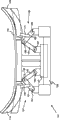
Referring to Fig. 1, show sketch according to the gravity-bending mould 1 of first aspect present invention.Gravity-bending mould 1 comprises intermediate mold and final mould.Intermediate mold has centre portions 4 and two tab portion 6,8.Centre portions 4 comprises two the isolated fixed mould sections 3 and 5 that can be almost parallel.Each fixed mould section 3,5 all has the corresponding setting surface 7,9 of going up, and in the vertical, last setting surface 7,9 can be smooth or crooked (being shown smooth among Fig. 1).Intermediate active die segments 11 with setting of going up surperficial 13 is installed in an end place of isolated die segments 3,5.Another intermediate active die segments 15 with setting of going up surperficial 17 is installed in the other end place of isolated die segments 3,5.Intermediate active die segments 11,15 can be same configuration or different.Intermediate active die segments 11,15 can be with respect to isolated installation section 3,5, is between the first location of open site and the intermediate mold second position in the closed position at intermediate mold and moves.In this certain embodiments, movable intermediate mold section is hinged.
Last setting surface 7,9,13 and 17 forms the middle periphery setting edge of intermediate mold when intermediate mold is closed.
Gravity-bending mould 1 also comprises final mould.Final mould comprises identical centre portions 4, two isolated fixed mould sections 3,5 just, and also have two final flexible mould sections 19,23.In a particular embodiment, final flexible mould section 19,23 is hinged.Final flexible mould section 19 is installed near an end place of the isolated die segments 3,5 the intermediate active die segments 11.Final flexible mould section 23 is installed near the other end place of the isolated die segments 3,5 the intermediate active die segments 15.Two final flexible mould sections 19,23 can be same configuration, or different.Each final flexible mould section 19,23 all has the corresponding setting surface 21,25 of going up.When final mould was closed, final periphery setting edge was just formed by last setting surface 7,9,21,25.
Intermediate mold is installed on the bearer frame 27 by supporting leg 26.Because final mould has isolated die segments 3,5 jointly, what then those skilled in the art was easy to recognize is that for this specific embodiment, final mould also is installed on the bearer frame 27.Bearer frame 27 is installed on the mould bearer frame 29, and can vertically move with respect to it.Provide any suitable fabricated section of the vertical motion between bearer frame 27 and the mould bearer frame 29 all can use.As preferably, bearer frame 27 is installed on the mould bearer frame 29 by the linkage pivotally, makes that bearer frame 27 can be around the pivotal axis rotation, and this pivotal axis longitudinally extends to the other end (that is, in the direction of arrow A) from an end of mould.
In this particular example, intermediate active die segments 11,15 is positioned at the inboard of final flexible mould section 19,23.The mould that makes up according to first aspect present invention can have one or each and be positioned at the intermediate active die segments in the corresponding final flexible mould section outside.
All by corresponding mechanical linkage 37,39(only schematically shows in Fig. 1 each flexible mould section 19,23) be connected on the intermediate mold.In this embodiment, mechanical linkage 37 is connected to fixed mould section 5 on the final flexible mould section 19, and mechanical linkage 39 is connected to fixed mould section 5 on the final flexible mould section 23.Each mechanical linkage all can be connected on the identical or different fixed mould section at one end.
When in the closed position and final mould was in the open site when middle mould, mould 1 just was in first and arranges.Intermediate mold is moved with respect to final mould verticallydownwardly impels intermediate mold to move with respect to mechanical linkage 37,39.This impels mechanical linkage 37,39 to move to second structure from first structure then again, thereby impels corresponding final flexible mould section 19,23 to move to the position that final mould is closed from the position of final mold open.Mould 1 it is said that then being in second arranges.
When mould was in first layout, intermediate mold was just closed, and setting surface 13,17 is in the top on setting surface 21,25.When mould was in second layout, final mould was just closed, and went up the top that setting surface 21,25 is in the surface 13,17 that formalizes.Be in second when arranging to mould when mould is in first when arranging, the position with respect to mould bearer frame 29 of last setting surperficial 7,9 can be different.When the gravity-bending mould was in first layout and second layout, mould bearer frame 29 was the fixed datum of gravity bending mould.That is to say that intermediate mold and final mould move with respect to mould bearer frame 29.
In Fig. 1, intermediate active die segments 11,15 and final flexible mould section 19,23 be roughly ' V' shape.Flexible mould section 11,15,19,23 can have other structure, and for example, they can be ' U' shape, ' L' shape or are roughly straight line, and this depends on the shape of sheet glass with bending.
The upward setting surface of each in intermediate active die segments 11,15 and the final flexible mould section 19,23 can have different degree of curvatures.Particularly, if flexible mould section 11,15,19,23 is non-directional, for example, ' V' shape, then each corresponding setting surface 13,17,21,25 of going up can comprise the zone that curvature is different.For example, can have different degree of curvatures if the flexible mould section is each supporting leg of ' V' shape, then ' V', it can be smooth.
Fig. 2 shows the side-view according to the gravity-bending mould 101 of first aspect present invention in more detail.This gravity-bending mould structure with the above-mentioned gravity-bending mould that is used for Fig. 1 basically is identical, and just each mechanical linkage is connected to intermediate mold on the corresponding final flexible mould section by bearer frame.That is to say that mechanical linkage comprises the part of the bearer frame that intermediate mold is mounted thereon.Hereinafter will illustrate and describe mechanical linkage in more detail.
Intermediate mold comprises two isolated fixed mould sections 103, and 105(only illustrates 105) and two intermediate active die segments 111,115.Each intermediate active die segments 111,115 all has the corresponding setting surface 113,117 of going up.Intermediate mold is installed on the bearer frame 127.
Intermediate mold is shown that both are in raised position with respect to final mould and mould bearer frame 129.Because intermediate mold is installed on the bearer frame 127 by supporting leg 126, then bearer frame 127 also is in raised position with respect to mould bearer frame 29.Bearer frame 127 is arranged on raised position by making the bearer frame 127 and the releasable descending mechanism (not shown) down of mould bearer frame 129 interconnection.Each intermediate active die segments 111,115 all can be around corresponding pivot 134,135 rotations between open site and off-position.Intermediate active die segments 111,115 is shown with respect to fixed mould section 103, and 105(only shows die segments 105) be in the open site.In this specific embodiment, intermediate active die segments 111,115 is hinged.
Each intermediate active die segments 111,115 all has the corresponding setting surface 113,117 of going up.
Final mould comprises two isolated fixed mould sections 103, and 105(only illustrates 105) and final flexible mould section 119,123.Each final flexible mould section 119,123 all has the corresponding setting surface 121,125 of going up.The part of final mould is installed on the bearer frame 127.Another part of final mould is installed on the mould bearer frame 129.
Intermediate mold is communicated with by corresponding mechanical linkage 137,139 and two final flexible mould section 119,123 machineries.
In this particular example, each mechanical linkage 137,139 all is connected on the bearer frame 127 by corresponding pivot fabricated section 141,143.Similar pivot mounting 145,147 is connected on the mould bearer frame 129.Those skilled in the art will be easy to be clear that, in this specific embodiment, the mechanical linkage that intermediate mold is connected on the final flexible mould section comprises mechanical linkage 137(or 139), the part of bearer frame 127, pivot mounting 141(or 143) and supporting leg 126.In the modification of this embodiment, the end that is shown the mechanical linkage 137,139 that is connected on the pivot mounting 141,143 can be suitable for directly being connected on arbitrary fixed mould section.As alternative, the end that is shown the mechanical linkage 137,139 that is connected on the pivot mounting 141,143 can be suitable for directly being connected on arbitrary intermediate active die segments.
There is descending mechanism (not shown) under the release that makes bearer frame 127 and 129 interconnection of mould bearer frame.At first, releasable down descending mechanism is arranged on bearer frame 127 on the raised position with respect to mould bearer frame 129.
Fig. 3 shows intermediate mold in the closed position and is in the final mould of open site.Gravity-bending mould 101 is shown and is in first layout.Intermediate active die segments 111,115 is shown around 134,135 rotations of its corresponding pivot, makes intermediate mold in the closed position.The periphery setting edge that setting surface 107,109 forms intermediate mold of going up of going up setting surface 113,117 and die segments 103,105 of intermediate active die segments 111,115.Fixed mould section 103 is not shown in this Figure.
In Fig. 4, mould 101 was shown between the tour that is arranged into the layout of second shown in Fig. 5 from first shown in Fig. 3.
Releasable descending mechanism (not shown) is down actuated, and causes bearer frame 127 to fall towards mould bearer frame 129 verticallydownwardlies under the effect of gravity.Intermediate mold moves with respect to final mould verticallydownwardly, and at the same time, final mould and intermediate mold all move with respect to mechanical linkage 137,139.Downward vertical motion can or provide by linear actuator assistance.
The motion straight down that is bearing in the intermediate mold on the bearer frame 127 causes connecting parts 149 along clockwise direction around pivot pin 155 rotations.Because connecting parts 149 is connected on the connecting parts 151 by pivot pin 153 pivotallies, then connecting parts 149 is rotated in a clockwise direction around pivot pin 157 around clockwise direction rotation just the impelling connecting parts 151 of pivot pin 155.Therefore, just cause final flexible mould section 119 to move into off-position, this is because final flexible mould section is mechanically connected on the connecting parts 151 by connection element 159.
The motion straight down that is bearing in the intermediate mold on the bearer frame 127 also impels connecting parts 161 167 rotations along counter-clockwise direction around pivot pin.Because connecting parts 161 is connected on the connecting parts 163 by pivot pin 165 pivotallies, then connecting parts 161 just impels connecting parts 163 around pivot pin 169 counterclockwise turnings around the counterclockwise turning of pivot pin 167.Therefore, just cause final flexible mould section 123 to move into off-position, this is because final flexible mould section 123 is mechanically connected on the connecting parts 163 by connection element 171.
Because mechanical linkage 137,139 pivotallies are installed in the other end place of an end and the bearer frame 127 of stationary mold bearer frame 129, so bearer frame 127 just impels mechanical linkage 137,139 synchronously to move with respect to the downward vertical motion of mould bearer frame 129.Therefore, final flexible mould section 119,123 enters motion in the off-position just with synchronized with each other, and also with bearer frame 127(and therefore intermediate mold) move downward synchronous.The advantage that this had is, symmetric flecition is offered the left-hand side and the right-hand side of final mould, and final bending glass sheet produces better, more uniform optical property thereby make.
Additional synchronous device can be provided as in order to assist cutting out of final mould, and for example, linear actuator or the counterweight that is fit to install can be provided as and be used for one or two final flexible mould section.
Gravity-bending mould 101 is suitable for being configured such that by intermediate mold in off-position with respect to final flexible mould section 119,123(and therefore final flexible mould) move straight down, the bending glass sheet in the middle of being bearing on the periphery setting edge just can arrange that from first being converted to second be subjected to constant during arranging and support at the gravity-bending mould.Arrange since first at the gravity-bending mould to be converted to second when arranging, bending glass sheet only is subjected to the periphery setting edge supporting of intermediate mold in the closed position at first.The gravity-bending mould from first arrange be converted to second arrange during, bending glass sheet 175 just can be bearing in by edge, middle neighboring and finally the neighboring along neighboring that both constitute along last.This is temporary transient edge, neighboring.Arrange that from first be converted to second arranges when finishing at the gravity-bending mould, bending glass sheet is just only by the periphery setting edge supporting of final mould in the closed position.
First arranges that the transformation between arranging with second can take place soon, make bending glass sheet not free sagging fully under gravity come have a few and contact temporary transient edge, neighboring.
Those skilled in the art should be clear that easily that Fig. 4 shows the gravity-bending mould that is in temporary transient layout, and this temporary transient layout is between first layout and second is arranged.
In Fig. 5, mould 101 is shown and is in second layout.Intermediate mold is shown the lowering position that is in respect to supporting frame 129, and this is because bearer frame 127 descends by discharging releasable supporting device (not shown).When middle mould descended, final flexible mould section 119,123 just moved in the make-position, made to go up the top of setting surface 121,125 on last setting surface 113,117.The motion that two final die segments 119,123 enter in the off-position is synchronous, because mechanical linkage 137,139 is communicated with bearer frame 127 machineries at one end, and in the other end place and 129 mechanical connections of stationary mold bearer frame.By having the mechanical linkage that is equal to or roughly is equal to, the motion of two final flexible mould sections 119,123 just can be synchronous.
Utilize final flexible mould section in the closed position as shown in Figure 5, the upward setting surface 121,125 of die segments 103,105 and last setting surface 107,109 just form the periphery setting edge of final mould.Note only show die segments 105 among this figure, but this mould having the structure similar to mould shown in Fig. 1.Bending glass sheet 177 with final desired curvature be shown be bearing in final mould the neighboring along last.
In Fig. 6, glass bending equipment 81 is shown gravity-bending mould 101 and the mould mechanism 83 that comprises as shown in Figure 5.Mould mechanism 83 comprises formpiston 85 and is used for mould 85 along linear actuator mechanism 87 that arrow 89 directions move up and down vertically.Mould mechanism can be used for providing the power of the addition bend except that gravity, and can be used for producing and only be difficult to some desired curved glass shapes of producing by gravity-bending.Mould can be used for bending glass sheet on being supported on final periphery setting edge the time.
When using mould mechanism, closing final mould can be synchronous with moving downward of formpiston.Additional synchronous device moves downward formpiston and cuts out final mould and can be provided as cutting out of the final mould of assistance synchronously, for example, and linear actuator or suitable counterweight of installing.
Fig. 7 shows the schematic end of the similar gravity-bending mould 201 shown in structure and Fig. 1.Gravity-bending mould 201 is observed along the direction of the arrow A in Figure 1.Gravity-bending mould 201 also has and the similar structure of aforementioned gravity-bending 101 moulds.Fig. 7 (and Fig. 8) shows a kind of specific mode that intermediate mold is moved with respect to final mould verticallydownwardly.
In the figure, for clarity sake, not shown final mould.Intermediate mold comprises the intermediate active section 211 that is installed in mould one end place.Intermediate mold is installed on the bearer frame 227 by supporting leg 226.Bearer frame 227 is installed on the mould bearer frame 229 by hinge component 260.Hinge component comprises first hinge member 261 and second hinge member 263 that is connected on the bearer frame 227 that is connected on the mould bearer frame 229.Hinge member 261,263 is connected by pivot pin 265 pivotallies, makes that bearer frame 227 can be with respect to mould bearer frame 229 around pivot pin 265 rotations.Can have more than one hinge component, for example, the each end at mould that is to say, end 6 of pointing out in as Fig. 1 and 8 places.
Gravity-bending mould 201 is shown in Fig. 7 and is in first layout.Releasable descending mechanism (not shown) down makes bearer frame 227 and 229 interconnection of mould bearer frame.
Existence is connected to mechanical linkage 237 on the final flexible mould section (not shown) with intermediate mold.Notice that mechanical linkage 237 is connected on the intermediate mold by bearer frame 227 and supporting leg 226.As indicated above, exist a kind of specific mode that final flexible mould section is connected on the intermediate mold.
The other end of connecting parts 251 is connected on the connecting parts 249.The other end of connecting parts 249 is installed on another ball-and-socket type fabricated section 256.Pin 255 extends through the ball-and-socket type fabricated section, and is arranged to rotate around pivot mounting 241 pivots that are installed on the bearer frame 227.Connection element 259 is connected on the connecting parts 251, and connecting parts 251 is connected on the final flexible mould section (not shown).The ball-and-socket type fabricated section provides a kind of mode of gimbal type fabricated section.
Fig. 8 shows and is in the second gravity-bending mould of arranging 201.Make that the descending mechanism (not shown) discharges under release of bearer frame 227 and mould bearer frame 229 interconnection.Bearer frame 227 rotates around pivot pin 265 under the effect of gravity, thereby impels intermediate mold to move towards mould bearer frame 229 verticallydownwardlies.This time to vertical motion impel final mould to close with the similar fashion of describing with reference Fig. 4 and Fig. 5.
Because bearer frame 227 is around pivot pin 265 rotations, mechanical linkage just must be able to adapt to the horizontal shift of bearer frame 227.This is to be realized by ball-and-socket type fabricated section 245,256.Connection element 249,251 rotates as described in reference Fig. 4 and Fig. 5, but in addition, connection element can be around another pivotal axis rotation, to adapt to the horizontal shift of bearer frame 227.The ball-and-socket type fabricated section can be substituted by the fabricated section of any kind that this type of pair pivotal axis is provided to connecting parts 249 and 251, for example, and a pair of vertically disposed pivot pin above another.
Can use a alternate manner of realizing in intermediate mold and the final mould, and at least one in intermediate mold and the final mould moves with respect to mechanical linkage simultaneously with respect to another motion, for example, linear actuator.
Those skilled in the art will be easy to be clear that, can not have the center die section according to the gravity-bending mould of first aspect present invention, and in the case, the intermediate active die segments will be mounted to toward each other under the situation that does not have die segments to get involved.In addition, those skilled in the art will be easy to be clear that intermediate mold and final mould can not have shared any die segments, and in the case, intermediate mold can be bearing on the intermediate support framework, and final mould can be bearing on the final bearer frame.In this embodiment, can pass the intermediate mold of intermediate support framework and finally can have mechanical linkage between the flexible mould section, so that in intermediate mold and the final mould one is moved vertically with respect to another, and simultaneously, in intermediate mold and the final mould at least one moves with respect to mechanical linkage, impel the gravity-bending mould between first layout and second is arranged, to move, thereby impel final flexible mould section to move to off-position from the open site.
In other improvement project, each in intermediate mold and the final mould all can only have near the single-unit activity section mould one end place is installed in each other.
Crooked work will be described now.
With reference to Fig. 2 to Fig. 5, at first, glass plate 136 is placed on the intermediate mold, and intermediate active die segments 111,115 is in the approximate horizontal position of rising.Releasable descending mechanism (not shown) down has been ready to, so that bearer frame 127(and so intermediate mold) be arranged on respect on the final mould raised position of (with mould bearer frame 129).Intermediate active die segments 111,115 is arranged on the position of approximate horizontal, and remains on this position by the weight and the rigidity of glass plate 136.As the usual manner in this area, by such as the isolating sheet glass lamination of the suitable separating agent of lime carbonate, for example a pair of sheet glass can be crooked simultaneously.
The assembly of sheet glass 136 and gravity-bending mould 101 heats in normal reheating furnace or annealing furnace.When glass heats, it is softening, and loses its rigidity.Therefore, each in the intermediate mold section 111,115 can little by little rotate to off-position around corresponding pivot 134,135 usually under the influence of the counterweight (not shown) that is connected thereto.Sheet glass is bent to intermediate shape 173 on intermediate mold in the closed position.With reference to Fig. 3, sheet glass 173 is bearing on the periphery setting edge of intermediate mold.The gravity-bending mould is in first then and arranges.
In the specific moment, releasable descending mechanism down can be threaded off by the actuation mechanism that is fit to.When releasable following descending mechanism discharged, bearer frame 127 just moved with respect to final mould (with mould bearer frame 129) verticallydownwardly.Because bearer frame is by corresponding mechanical linkage 137,139 with final flexible mould section 119,123 machineries are communicated with, so the vertical motion of bearer frame (and so intermediate mold in the closed position) just impels final flexible mould section 119,123 to rotate to off-position.
What be in corresponding final flexible mould section 119,123 that the first gravity-bending mould of arranging 101 has goes up the belows of going up setting surface 113,117 of setting surface 121,125 in corresponding adjacent intermediate active die segments 111,115.When bearer frame 127 descended, bending glass sheet 173 was subjected to the continuous supporting of at least a portion on setting surface 113,117, and simultaneously, final flexible mould section 119,123 rotations occupy its position through corresponding intermediate active die segments 111,115.
Passed through corresponding intermediate active die segments at 111,115 o'clock when final flexible mould section 119,123 rotates, sheet glass is just by the part on last setting surface 113,117 and the part supporting on last setting surface 121,125.When final flexible mould section 119,123 when moving on the off-position, and the sheet glass that is in the tab portion just bends to net shape, and the sheet glass that is in the tab portion is bearing in corresponding final flexible mould section 119,123 go up on the setting surface 121,125.In whole crooked work, sheet glass keeps being supported, and making can not reverse bending.The sheet glass that is bearing on the final periphery setting edge is shown 177 in Fig. 5.
When releasable down descending mechanism discharged, each mechanical linkage 137,139 all moved to second constructing as shown in Figure 5 from first structure as Fig. 2 and Fig. 3 as shown in.
Sketch according to the bending glass sheet equipment 300 of fourth aspect present invention has been shown among Fig. 9.Bending glass sheet equipment 300 comprises (with reference to the described type of Fig. 2 to Fig. 5) a plurality of gravity-bending moulds according to first aspect present invention.Bending glass sheet equipment 300 comprises process furnace or annealing furnace 302, and the conveyor system 304 that is used for the gravity-bending mould is conveyed through along the direction of arrow 305 process furnace.The assembly of sheet glass and bending mould 306 passes process furnace 302.When glass heats, it is softening, and little by little sagging downwards under gravity, allows that the intermediate active die segments can little by little rotate up around the corresponding pivot axis under the effect of counterweight, thus bending glass sheet and close intermediate mold little by little.Then, mould is in as first shown in 308 and arranges.
After desired middle curvature is introduced in the sheet glass, on the specific moment or the specific position in the process furnace, the release that makes the interconnection of bearer frame and mould bearer frame down descending mechanism use actuator 310 is actuated, and impels bearer frame to fall vertically towards the mould bearer frame.Actuator 310 can be in the heating anneal stove inboard or the outside.
When bearer frame and intermediate mold fall,,, thereby rotate to the off-position shown in 312 so final flexible mould section is subjected to the promotion that makes progress owing between intermediate mold and the final flexible mould section mechanical linkage is arranged under action of gravity.Mould is in second then and arranges.At crooked on period, sheet glass is bearing on the lateral margin always.
At first, the neighboring was along last in the middle of bending glass sheet only was bearing in.Arrange from first when mould to move to second when arranging, final flexible mould section so that occupy its position, thereby proposes intermediate active die segments with glass just through the intermediate active die segments.Close up to final mould, sheet glass just partly is bearing on the lateral margin by the surperficial part of setting on formalize on the intermediate active die segments a surperficial part and the final flexible mould section.Because final flexible mould section has the degree of curvature that is higher than the intermediate active die segments,, contact the setting surface of final flexible mould section up to the bottom of sheet glass so the sheet glass continuation is sagging.Sheet glass is bent to desired net shape then.
When middle mould descends, owing to the mechanical linkage of final flexible mould section by roughly the same type is communicated with intermediate mold machinery, so final flexible mould section rotates to off-position simultaneously.The advantage that this provided is that the motion of final flexible mould section is with regard to synchronously, and this has allowed that improvement is to the control of glass setting to finally desired shape.
So just finished crooked work.Mould and the curved glass on it are passed to the rest part of process furnace 302, stand conventional annealing and cooling program.After bending mould withdrawed from the smelting furnace, bending glass sheet just removed from bending mould, and allowed cooling.Bending mould is back to the inlet of smelting furnace, and releasable down descending mechanism is ready to, and mould is loaded with sheet glass and carries out follow-up bend cycles.
In the alternatives of Fig. 9, advance when passing annealing furnace along the direction of arrow 305 when the assembly of sheet glass and bending mould, be shown at the sheet glass at 306,308 and 312 places and the assembly of bending mould and just can be arranged to and be oriented 90 ° shown in Fig. 9.
In a further embodiment, crooked work can comprise by suitably mould mechanism being positioned at the press-bending step in the heating anneal stove.Mould mechanism can be used for crooked sheet glass is bent to realize additional curvature in some zones that when glass support was on final periphery setting edge, these zones can not only be come crooked fully by gravity-bending.
The present invention has specific application in vehicle windscreen manufacturing in glass plate edge or the corner is introduced the curvature of higher degree in expectation.
The technological merit that embodiments of the invention provide is that the motion of final flexible mould section can be synchronous, makes to exist lateral margin or the glass bending in the corner to sheet glass that control is preferably arranged.Particularly, when having two relative final flexible mould sections, the motion of each final flexible mould section just can be synchronous, because between each final flexible mould section and the intermediate mold mechanical linkage is arranged.In addition, sheet glass can be supported in whole crooked work, and this has caused optical property preferably.Final curved glass shape is more even because each tab portion can be simultaneously crooked, thereby reduced that sheet glass moves on mould potential may with the potential of reverse bending may.
Claims (31)
1. a gravity-bending mould that is used for bending glass sheet comprises: final mould and the intermediate mold with middle periphery setting edge with final periphery setting edge; Described final mould comprises the final flexible mould section that is installed in described gravity-bending mould one end place, and described final flexible mould section has the setting of going up surface; Described intermediate mold comprises and is adjacent to the intermediate active die segments that described final flexible mould section is installed in described gravity-bending mould one end place that described intermediate active die segments has the setting of going up surface;
Wherein, described gravity-bending mould can move between first layout and second is arranged, wherein, arrange described first, described intermediate mold close and described intermediate active die segments go up that the setting surface is higher than described final flexible mould section go up the setting surface, arrange described second, described final mould close and described intermediate active die segments go up that the setting surface is lower than described final flexible mould section go up the setting surface;
And wherein, described final flexible mould section is connected on the described intermediate mold by mechanical linkage, so that in making described intermediate mold and described final mould one is when mobile vertically with respect to another, and when at least one in making described intermediate mold and described final mould moves with respect to described mechanical linkage, impel described gravity-bending mould between described first layout and described second is arranged, to move.
2. gravity-bending mould according to claim 1, it comprises described final mould and the shared fixed mould section of described intermediate mold, described fixed mould section has the setting of going up surface, the described of this fixed mould section goes up the part that the setting surface forms described middle periphery setting edge, and also forms the part at described final periphery setting edge.
3. gravity-bending mould according to claim 2, it is characterized in that, described fixed mould section is installed on first bearer frame, and described first bearer frame is installed on the mould bearer frame, makes in described intermediate mold and the final mould one can vertically come to move vertically with respect in described intermediate mold and the final mould another with respect to the motion of described mould bearer frame by described first bearer frame.
4. gravity-bending mould according to claim 3 is characterized in that, the described first bearer frame pivotally is installed on the described mould bearer frame.
5. gravity-bending mould according to claim 2 is characterized in that, described final flexible mould section mechanically is connected on the described fixed mould section.
6. gravity-bending mould according to claim 3 is characterized in that, described final flexible mould section mechanically is connected on the described fixed mould section.
7. gravity-bending mould according to claim 4 is characterized in that, described final flexible mould section mechanically is connected on the described fixed mould section.
8. gravity-bending mould according to claim 1, it comprises center fixed die segments and final fixed mould section, described center fixed die segments has the upward setting surface of a part that forms described middle periphery setting edge, and described final fixed mould section has the upward setting surface of the part at the described final periphery setting of formation edge; Described center fixed die segments can move with respect to described final fixed mould section, and wherein, when described gravity-bending mould is in described first when arranging, the upward setting surface of described center fixed die segments is higher than going up of described final fixed mould section and formalizes surperficial, and be in described second when arranging when described gravity-bending mould, described center fixed die segments go up that the setting surface is lower than described final fixed mould section go up the setting surface.
9. gravity-bending mould according to claim 8 is characterized in that, described center fixed die segments is installed near the described final fixed mould section.
10. gravity-bending mould according to claim 8, it is characterized in that, described center fixed die segments is installed on first bearer frame, and described final fixed mould section is installed on second bearer frame, and wherein, releasable descending mechanism down makes described first bearer frame and the interconnection of described second bearer frame, have and select and temporarily adjustment, described intermediate mold being arranged on initial raised position, and when being released, impel relative vertical motion between described intermediate mold and the described final mould with respect to described final mould.
11. gravity-bending mould according to claim 9, it is characterized in that, described center fixed die segments is installed on first bearer frame, and described final fixed mould section is installed on second bearer frame, and wherein, releasable descending mechanism down makes described first bearer frame and the interconnection of described second bearer frame, have and select and temporarily adjustment, described intermediate mold being arranged on initial raised position, and when being released, impel relative vertical motion between described intermediate mold and the described final mould with respect to described final mould.
12. gravity-bending mould according to claim 1 is characterized in that, described final mould comprises the second final flexible mould section at the other end place that is installed in described gravity-bending mould, and the described second final flexible mould section has the setting of going up surface; Described intermediate mold comprises being adjacent to the described second final flexible mould section installation and having goes up the second surperficial intermediate active die segments that formalizes, wherein, arrange described first, the upward setting surface of the described second intermediate active die segments is higher than going up of the described second final flexible mould section and formalizes surperficial, and wherein, the described second final flexible mould section is connected on the described intermediate mold by second mechanical linkage, so that move to described second when arranging arranging, to impel in the described second final flexible mould section immigration off-position from described first.
13. gravity-bending mould according to claim 12 is characterized in that, the described second final flexible mould section moves into described off-position when described final flexible mould section moves into off-position.
14. gravity-bending mould according to claim 1 is characterized in that, described mechanical linkage comprises can be around the connecting parts of two pivotal axis rotations.
15. gravity-bending mould according to claim 12 is characterized in that, described mechanical linkage and described second mechanical linkage include can be around the connecting parts of two pivotal axis rotations.
16., it is characterized in that described intermediate mold keeps closing during described first layout is transformed into described second layout at described gravity-bending mould according to any described gravity-bending mould among the aforementioned claim 1-15.
17. according to any described gravity-bending mould among the aforementioned claim 1-15, it is characterized in that in described intermediate mold and the described final mould one is disposed to the synchronized movement that motion between the described second described tour of arranging and described final flexible mould section enter off-position at described gravity-bending mould from described first.
18., it is characterized in that described final flexible mould section is hinged according to any described gravity-bending mould among the aforementioned claim 1-15.
19., it is characterized in that described intermediate active die segments is hinged according to any described gravity-bending mould among the aforementioned claim 1-15.
20., it is characterized in that described intermediate mold has the curvature less than described final mould according to any described gravity-bending mould among the aforementioned claim 1-15.
21., it is characterized in that described intermediate mold is positioned at the inboard of described final mould according to any described gravity-bending mould among the aforementioned claim 1-15.
22. according to any described gravity-bending mould among the aforementioned claim 1-15, it also includes the linear actuator that helps close described final mould.
23. bending glass sheet equipment, comprise according to any described gravity-bending mould among the aforementioned claim 1-22, and being arranged to the mould mechanism that moves vertically with respect to described gravity-bending mould, described mould mechanism comprises being used to formalize and is bearing in the formpiston of the sheet glass upper surface on the described final periphery setting edge.
24. bending glass sheet equipment, comprise according to any described a plurality of gravity-bending moulds, smelting furnace in the claim 1 to 22, be used for described a plurality of gravity-bending moulds are conveyed through continuously the conveyor system of described smelting furnace, described smelting furnace is included in the actuation mechanism that is arranged on the inboard or the outside of described smelting furnace along the pre-position of described furnace length, and described actuation mechanism is suitable for impelling when each corresponding gravity-bending mould transmits through described actuation mechanism described gravity-bending mould to arrange that from described first moving to described second arranges.
25. bending glass sheet equipment according to claim 24, it comprises and is arranged to the mould mechanism that moves vertically with respect to one in the described gravity-bending mould, described mould mechanism comprises formpiston, and described formpiston is used to formalize and is bearing in the upper surface of the sheet glass on the described final periphery setting edge.
26. the method for a gravity bending glass sheets said method comprising the steps of: the gravity-bending mould (a) is provided, and this gravity-bending mould comprises final mould with final periphery setting edge and the intermediate mold with middle periphery setting edge; Described final mould comprises the final flexible mould section that is installed in described gravity-bending mould one end place, and described final flexible mould section has the setting of going up surface; Described intermediate mold comprises and is adjacent to the intermediate active die segments that described final flexible mould section is installed in described gravity-bending mould one end place; Described intermediate active die segments has the setting of going up surface; Described final flexible mould section is connected on the described intermediate mold by mechanical linkage; (b) described intermediate mold is arranged on the raised position with respect to described final mould; (c) glass plate is placed on the described intermediate mold, described intermediate active die segments is in the open site of approximate horizontal simultaneously, and described glass plate is supported by at least a portion of described intermediate active die segments when described intermediate mold is on the open site; (d) come the described glass plate of gravity-bending in smelting furnace by heating described sheet glass, described heating can cause the softening of described sheet glass, thereby the described sheet glass of gravity-bending, described gravity-bending step comprises two stages: (i) fs, wherein, described glass plate is bent to the bent intermediate shape by described intermediate mold, make described bending glass sheet be bearing on the described middle periphery setting edge, and the subordinate phase after the (ii) described fs, wherein, described final flexible mould section is arranged on the raised position with respect to described intermediate active die segments, and by closing described final mould, make described sheet glass be bent to final curved shape from described bent intermediate shape, so that described bending glass sheet is bearing on the described final periphery setting edge, wherein, proceed to described subordinate phase from the described fs, one in described intermediate mold and the described final mould is moved with respect to another, simultaneously, in described intermediate mold and the described final mould at least one moves with respect to described mechanical linkage, so that impel described final flexible mould section to move up, so that replace described intermediate active die segments with respect to described intermediate active die segments.
27. the method for gravity bending glass sheets according to claim 26, it is characterized in that, described intermediate mold is installed on first bearer frame, and described first bearer frame is installed on the mould bearer frame, and proceeding to the described subordinate phase from the described fs, by described first bearer frame is moved with respect to described mould bearer frame described intermediate mold is moved.
28. the method for gravity bending glass sheets according to claim 27, it is characterized in that, described first bearer frame is installed on the described mould bearer frame by the linkage pivotally with pivotal axis, and proceeding to the subordinate phase from the described fs, described first bearer frame is around described pivotal axis rotation.
29. method according to any described gravity bending glass sheets in the claim 26 to 28, it is characterized in that, one the motion in described intermediate mold and the described final mould and the synchronized movement of described final flexible mould section make described sheet glass be supported serially when moving to described subordinate phase from the fs.
30. method according to any described gravity bending glass sheets in the claim 26 to 28, it is characterized in that, this method also comprises the bending step that mould is assisted, the bending step that described mould is assisted is used for when described sheet glass is bearing on described middle periphery setting edge and/or the described final periphery setting edge, the described sheet glass of setting under the effect that applies power.
31. the method for gravity bending glass sheets according to claim 29, it is characterized in that, this method also comprises the bending step that mould is assisted, the bending step that described mould is assisted is used for when described sheet glass is bearing on described middle periphery setting edge and/or the described final periphery setting edge, the described sheet glass of setting under the effect that applies power.
Applications Claiming Priority (3)
| Application Number | Priority Date | Filing Date | Title |
|---|---|---|---|
| GBGB0810001.8A GB0810001D0 (en) | 2008-06-02 | 2008-06-02 | Gravity bending glass sheets |
| GB0810001.8 | 2008-06-02 | ||
| PCT/GB2009/050598 WO2009147423A1 (en) | 2008-06-02 | 2009-06-01 | Gravity bending glass sheets |
Publications (2)
| Publication Number | Publication Date |
|---|---|
| CN102046544A CN102046544A (en) | 2011-05-04 |
| CN102046544B true CN102046544B (en) | 2013-07-24 |
Family
ID=39637985
Family Applications (1)
| Application Number | Title | Priority Date | Filing Date |
|---|---|---|---|
| CN2009801201664A Active CN102046544B (en) | 2008-06-02 | 2009-06-01 | Gravity bending glass sheets |
Country Status (8)
| Country | Link |
|---|---|
| US (1) | US8459061B2 (en) |
| EP (1) | EP2297056B1 (en) |
| JP (1) | JP5620369B2 (en) |
| CN (1) | CN102046544B (en) |
| BR (1) | BRPI0912893B1 (en) |
| GB (1) | GB0810001D0 (en) |
| PL (1) | PL2297056T3 (en) |
| WO (1) | WO2009147423A1 (en) |
Families Citing this family (16)
| Publication number | Priority date | Publication date | Assignee | Title |
|---|---|---|---|---|
| US8375746B2 (en) * | 2007-07-16 | 2013-02-19 | Clarion Technologies, Inc. | Frameless spill-safe shelf |
| FR2942793B1 (en) * | 2009-03-05 | 2012-03-23 | Saint Gobain | FORMING A GLAZING COMPRISING AN OPENING |
| US9296637B2 (en) | 2010-06-09 | 2016-03-29 | Glasstech, Inc. | Method for press forming glass sheets |
| DE102010036999B4 (en) * | 2010-08-16 | 2016-07-28 | Schott Ag | Process for producing a bent glass or glass ceramic molding |
| FR2987833B1 (en) * | 2012-03-06 | 2014-03-14 | Saint Gobain | ARTICULATION BOMBING SUPPORT |
| US10526232B2 (en) | 2013-05-30 | 2020-01-07 | Ppg Industries Ohio, Inc. | Microwave heating glass bending process |
| US9108875B2 (en) * | 2013-05-30 | 2015-08-18 | Ppg Industries Ohio, Inc. | Heating and shaping system using microwave focused beam heating |
| FR3017865A1 (en) * | 2014-02-27 | 2015-08-28 | Saint Gobain | GRAVITY BOMBAGE ON DOUBLE SUPPORT |
| TWI676065B (en) | 2017-08-11 | 2019-11-01 | 友達光電股份有限公司 | Display device with adjustable curvature |
| FR3080616A1 (en) * | 2018-04-27 | 2019-11-01 | Saint-Gobain Glass France | SYMMETRIC BOMBAGE |
| US11542189B2 (en) * | 2020-09-03 | 2023-01-03 | Glasstech, Inc. | Articulated mold arrangement for a glass processing system |
| CN111925105B (en) * | 2020-09-03 | 2021-02-26 | 海安明光光学玻璃科技有限公司 | Hot bending glass manufacturing machine |
| CN112679076B (en) * | 2021-01-05 | 2021-07-27 | 广东南星玻璃有限公司 | Mold for glass hot bending device and forming method based on mold |
| CN114163113B (en) * | 2021-11-30 | 2023-03-28 | 福耀玻璃工业集团股份有限公司 | Concave die, forming die, glass forming system and glass forming method |
| CN114772909B (en) * | 2022-04-12 | 2023-12-05 | 福建省万达汽车玻璃工业有限公司 | Curved glass forming die |
| US20230348312A1 (en) * | 2022-04-29 | 2023-11-02 | Glasstech, Inc. | Station and method for forming glass sheets |
Citations (4)
| Publication number | Priority date | Publication date | Assignee | Title |
|---|---|---|---|---|
| CN1533365A (en) * | 2002-03-13 | 2004-09-29 | ������������ʽ���� | Method and apparatus for bending a glass sheet |
| CN2820858Y (en) * | 2005-05-14 | 2006-09-27 | 福耀玻璃工业集团股份有限公司 | Forming mould with balance side wing |
| EP0885851B1 (en) * | 1997-06-16 | 2006-12-13 | PPG Industries Ohio, Inc. | Apparatus and method for bending glass sheets |
| FR2894955A1 (en) * | 2005-12-20 | 2007-06-22 | Saint Gobain | Device for the gravity cambering of glass sheets on a multiplicity of different forms of support with a controlled transition of the form or the support during cambering |
Family Cites Families (17)
| Publication number | Priority date | Publication date | Assignee | Title |
|---|---|---|---|---|
| US3281231A (en) * | 1958-02-17 | 1966-10-25 | Pittsburgh Plate Glass Co | Bending mold for glass sheets |
| US3364005A (en) * | 1958-06-25 | 1968-01-16 | Libbey Owens Ford Glass Co | Apparatus for bending glass sheets |
| GB956021A (en) * | 1960-10-31 | 1964-04-22 | Pittsburgh Plate Glass Co | Glass bending moulds |
| FR1320422A (en) | 1961-05-16 | 1963-03-08 | Pittsburgh Plate Glass Co | Improvements to devices for bending glass plates, and bending process |
| US3284183A (en) * | 1965-10-21 | 1966-11-08 | Pittsburgh Plate Glass Co | Glass sheet bending mold with pivoted end sections |
| US4804397A (en) * | 1987-12-16 | 1989-02-14 | Ppg Industries, Inc. | Partial press in gravity bending furnace and method of use |
| AU603958B2 (en) | 1988-10-20 | 1990-11-29 | O'brien Glass Industries Ltd. | Improved glass bending method |
| FR2659957B1 (en) | 1990-03-20 | 1993-07-16 | Saint Gobain Vitrage Int | METHOD AND DEVICE FOR THE BOMBING OF GLASS SHEETS. |
| GB9304286D0 (en) * | 1993-03-03 | 1993-04-21 | Pilkington Glass Ltd | Bending apparatus |
| FR2709483B1 (en) | 1993-08-31 | 1995-10-20 | Saint Gobain Vitrage Int | Method and device for bending glass sheets. |
| FR2725194B1 (en) * | 1994-10-04 | 1996-10-31 | Saint Gobain Vitrage | METHOD AND DEVICE FOR THE BOMBING OF GLASS SHEETS |
| JPH11157857A (en) * | 1997-11-19 | 1999-06-15 | Asahi Glass Co Ltd | Method for bending glass sheet and apparatus therefor |
| US6006549A (en) | 1998-11-12 | 1999-12-28 | Ppg Industries Ohio, Inc. | Bending mold having side mounted weight assemblies and method of use thereof |
| JP2002241140A (en) * | 2001-02-13 | 2002-08-28 | Asahi Glass Co Ltd | Apparatus and method for bending glass plate |
| JP4811774B2 (en) | 2001-04-10 | 2011-11-09 | 旭硝子株式会社 | Glass plate bending apparatus and forming method |
| GB0624190D0 (en) | 2006-12-04 | 2007-01-10 | Pilkington Glass Ltd | Gravity bending glass sheets |
| GB0724162D0 (en) * | 2007-12-11 | 2008-01-23 | Pilkington Group Ltd | Gravity bending glass sheets |
-
2008
- 2008-06-02 GB GBGB0810001.8A patent/GB0810001D0/en not_active Ceased
-
2009
- 2009-06-01 WO PCT/GB2009/050598 patent/WO2009147423A1/en active Application Filing
- 2009-06-01 EP EP09757795.1A patent/EP2297056B1/en active Active
- 2009-06-01 BR BRPI0912893A patent/BRPI0912893B1/en active IP Right Grant
- 2009-06-01 PL PL09757795T patent/PL2297056T3/en unknown
- 2009-06-01 US US12/995,222 patent/US8459061B2/en active Active
- 2009-06-01 CN CN2009801201664A patent/CN102046544B/en active Active
- 2009-06-01 JP JP2011512210A patent/JP5620369B2/en active Active
Patent Citations (4)
| Publication number | Priority date | Publication date | Assignee | Title |
|---|---|---|---|---|
| EP0885851B1 (en) * | 1997-06-16 | 2006-12-13 | PPG Industries Ohio, Inc. | Apparatus and method for bending glass sheets |
| CN1533365A (en) * | 2002-03-13 | 2004-09-29 | ������������ʽ���� | Method and apparatus for bending a glass sheet |
| CN2820858Y (en) * | 2005-05-14 | 2006-09-27 | 福耀玻璃工业集团股份有限公司 | Forming mould with balance side wing |
| FR2894955A1 (en) * | 2005-12-20 | 2007-06-22 | Saint Gobain | Device for the gravity cambering of glass sheets on a multiplicity of different forms of support with a controlled transition of the form or the support during cambering |
Also Published As
| Publication number | Publication date |
|---|---|
| PL2297056T3 (en) | 2016-01-29 |
| JP2011521885A (en) | 2011-07-28 |
| CN102046544A (en) | 2011-05-04 |
| WO2009147423A1 (en) | 2009-12-10 |
| US20110100060A1 (en) | 2011-05-05 |
| EP2297056A1 (en) | 2011-03-23 |
| GB0810001D0 (en) | 2008-07-09 |
| BRPI0912893B1 (en) | 2020-02-04 |
| EP2297056B1 (en) | 2015-08-12 |
| US8459061B2 (en) | 2013-06-11 |
| JP5620369B2 (en) | 2014-11-05 |
| BRPI0912893A2 (en) | 2015-10-20 |
Similar Documents
| Publication | Publication Date | Title |
|---|---|---|
| CN102046544B (en) | Gravity bending glass sheets | |
| KR100316858B1 (en) | Glass sheet bending method and apparatus | |
| JP5450084B2 (en) | Gravity bending of glass plate | |
| CN101605733A (en) | Gravity bending glass sheets | |
| US9499427B2 (en) | Articulated bending support | |
| CN105008294B (en) | Gravity-bending on double bracket | |
| US8677784B2 (en) | Gravity bending glass sheets | |
| CN110621626A (en) | Support for gravity bending of glass | |
| CN110650926A (en) | Symmetrical bending |
Legal Events
| Date | Code | Title | Description |
|---|---|---|---|
| C06 | Publication | ||
| PB01 | Publication | ||
| C10 | Entry into substantive examination | ||
| SE01 | Entry into force of request for substantive examination | ||
| C14 | Grant of patent or utility model | ||
| GR01 | Patent grant |