The application relates to the co-pending U. S. application No.12/564 of submission on September 22nd, 2009, and 339, incorporate its whole disclosures into this paper by reference at this.
Summary of the invention
Be used for the flow-field plate used at fuel cell by providing at least one embodiment, the invention solves one or more problems of prior art.The flow-field plate of this embodiment comprises the metallic plate with first surface and second surface.First surface defines a plurality of passages that are used to guide the first gaseous state composition to flow.Carbon-coating is placed at least a portion of metallic plate, and titanium oxide layer is placed at least a portion of this carbon-coating, is coated with the carbon bilayer of titanium oxide with formation.
In at least one embodiment, the carbon bilayer that is coated with titanium oxide has such surface, that is: this surface has the contact angle less than about 30 degree, and when flow-field plate is sandwiched between the carbon paper with 200psi, has less than 40mohm-cm
2Contact resistance.
In another embodiment, provide the fuel cell that comprises above-mentioned flow-field plate.This fuel cell comprises the first-class field plate with the carbon bilayer that has applied titanium oxide.First catalyst layer is placed on the first-class field plate.The ion conductor layer is placed on the first-class field plate, and second catalyst layer is placed on the ion conductor layer.At last, second flow-field plate is placed on second catalyst layer.Gas diffusion layers then provides as required.
In yet another embodiment, provide the method that is used to form above-mentioned flow-field plate.This method is included in and deposits carbon-coating on the metallic plate, and titanium deposition oxide skin(coating) on this carbon-coating then is so that form the bilayer of the carbon that is coated with titanium oxide.
The invention still further relates to following technical scheme:
1. 1 kinds of flow-field plate that are used for fuel cells applications of scheme comprise:
Metallic plate with first surface and second surface, described first surface define a plurality of passages that are used to guide the first gaseous state composition to flow;
Place the carbon-coating at least a portion of described metallic plate; With
Place the titanium oxide layer at least a portion of described carbon-coating, so that form titanium oxide/carbon bilayer.
Scheme 2. is as scheme 1 described flow-field plate, and wherein, the described carbon-coating that is coated with titanium oxide has the surface of contact angle less than 40 degree.
Scheme 3. is as scheme 1 described flow-field plate, and wherein, when described flow-field plate was clipped between the carbon paper with 200psi, contact resistance was less than 40mohm-cm
2
Scheme 4. is as scheme 1 described flow-field plate, and wherein, described titanium oxide layer optionally is deposited on a plurality of walls of described passage.
Scheme 5. also comprises the one or more other titanium oxide/carbon bilayer at least a portion that places described titanium oxide/carbon-coating as scheme 1 described flow-field plate.
Scheme 6. is as scheme 1 described flow-field plate, wherein, on the described titanium oxide layer amount of being included in less than the hydrocarbon of 40% percetage by weight of the total weight of described titanium oxide layer.
Scheme 7. is as scheme 1 described flow-field plate, wherein, on the described titanium oxide layer amount of being included in less than the hydrocarbon of 20% percetage by weight of the total weight of described titanium oxide layer.
Scheme 8. is as scheme 1 described flow-field plate, and wherein, described carbon-coating comprises amorphous carbon.
Scheme 9. is as scheme 1 described flow-field plate, and wherein, described carbon-coating comprises crystalline carbon.
Scheme 10. is as scheme 8 described flow-field plate, and wherein, described carbon-coating has average every square centimeter of surface that comprises at least 5 holes.
Scheme 11. is as scheme 1 described flow-field plate, and wherein, described titanium oxide layer comprises and being selected from by TiO
2, the low oxide, titanium oxide hydrate of titanium and the component in the group that their mixture is formed.
Scheme 12. is as scheme 1 described flow-field plate, and wherein, described titanium oxide layer comprises amorphous titanium oxide or polycrystalline titanium oxide.
Scheme 13. is as scheme 1 described flow-field plate, and wherein, described titanium oxide/carbon bilayer is activated by UV or plasma source, cleaning and maintenance hydrophily so that described surface becomes.
Scheme 14. is as scheme 1 described flow-field plate, and wherein, described titanium oxide/carbon bilayer is activated by visible light after utilizing the nitrogenous gas processing.
Scheme 15. is as scheme 1 described flow-field plate, and wherein, described titanium oxide/carbon bilayer is a hydrolysis-stable.
Scheme 16. is as scheme 1 described flow-field plate, and wherein, described metallic plate has second surface, and described second surface defines more than second passage that is used to guide the second gaseous state composition to flow.
Scheme 17. is as scheme 1 described flow-field plate, and wherein, described second surface is the second noncrystalline carbon-coating.
18. 1 kinds of fuel cells of scheme comprise:
First-class field plate comprises:
Metallic plate with first surface and second surface, described first surface defines and is used for
The a plurality of passages that guide the first gaseous state composition to flow;
Place the carbon-coating at least a portion of described metallic plate;
Place the titanium oxide layer at least a portion of described carbon-coating, so that form titanium oxide/carbon bilayer;
Place first catalyst layer on the described first-class field plate;
Place the ion conductor layer on described first catalyst layer;
Place second catalyst layer on the described ion conductor layer; With
Place second flow-field plate on described second catalyst layer.
Scheme 19., has less than 40mohm-cm when described flow-field plate is clipped between the carbon paper with 200psi as scheme 18 described fuel cells
2Contact resistance.
Scheme 20. is as scheme 18 described fuel cells, and wherein, described carbon-coating surface has the contact angle less than 30 degree.
Scheme 21. is as scheme 18 described fuel cells, and wherein, described titanium oxide layer comprises and being selected from by TiO
2, the low oxide, titanium oxide hydrate of titanium and the component in the group that their mixture is formed.
22. 1 kinds of methods of making flow-field plate of scheme, described flow-field plate comprises the metallic plate with first surface and second surface, described first surface defines a plurality of passages that are used to guide the first gaseous state composition to flow, carbon-coating is placed at least a portion of described metallic plate, and titanium oxide layer is placed at least a portion of described carbon-coating, so that form titanium oxide/carbon bilayer, described method comprises:
Carbon-coating is deposited on the described metallic plate;
Titanium oxide is deposited upon on the described carbon-coating to form described titanium oxide/carbon-coating; With
Activate described titanium oxide/carbon-coating.
Scheme 23. wherein, utilizes plasma to activate described carbon-coating surface as scheme 22 described methods.
From detailed description provided below, other exemplary embodiment of the present invention will become obviously.Should be understood that,, be intended to only be used for the purpose of explanation, and be not intended to limit the scope of the invention although these the detailed description and specific examples disclose exemplary embodiment of the present invention.
Embodiment
Now will be in detail with reference to the present invention current preferred composition, embodiment and method, it has constituted the current enforcement known for inventor best mode of the present invention that is.It is pro rata that these figure need not to be.Yet, it being understood that the disclosed embodiments all only are examples of the present invention, it can be implemented with various and substituting form.Therefore, detail disclosed herein should not be interpreted as restrictive, but as just the representative basis about any aspect of the present invention, and/or as being used to instruct those skilled in the art to use representative basis of the present invention in every way.
Unless in example, perhaps indicate clearly, otherwise whole digital quantities of having indicated quantity of material or reaction and/or service condition in this manual all should be understood that to be modified by word " approximately " when describing wide region of the present invention in other mode.Enforcement in described numerical limit is normally preferred.Equally, unless clear and definite statement on the contrary, otherwise: " percentage ", " ... part " and ratio are all according to the weight meter; Term " polymer " " comprise " oligomer ", " copolymer ", " terpolymer " etc.; It is suitable or preferred that one group or a class material are described as being used for the given purpose relevant with the present invention, and the mixture that has hinted any two or more members in this group or this class is suitable or preferred equally; Composition when the description of the composition in the technical terms of chemistry being related in any combination of appointment in adding this description to, and needn't get rid of the chemical interaction that mixes between the mix ingredients of back; The definition first time of acronym or other abbreviations is applicable to the whole identical abbreviation of using subsequently herein, and is applicable to the normal grammatical variants of the abbreviation of initial definition after necessity correction; And, unless clear and definite statement on the contrary, otherwise to the measurement of characteristic by as preamble or hereinafter about constructedly being determined that these identical characteristics are mentioned.
What it is also understood that is, the present invention is not limited to specific embodiment as described below and method, and this is because concrete parts and/or situation may change certainly to some extent.In addition, term used herein only is used for purpose that specific embodiment of the present invention is described, and is not intended to limit by any way.
Must be noted that also singulative " " and " being somebody's turn to do " all comprise plural object, unless context is clearly indicated in addition as employed in specification and the claims.For example, with singulative mentioning of parts is intended to comprise a plurality of parts.
In whole the application, when with reference to publication, whole disclosures of these publications are incorporated among the application by reference, so that describe the present situation of the technical field of the invention more completely.
As used in this article, term " roughness average " or " surface roughness average " are meant the arithmetic mean of the absolute value of profile (profile) elevation deviation.Roughness average can be determined according to ANSI B46.1.At this, by reference whole disclosures of this list of references are incorporated into.
In an embodiment of the present invention, provide a kind of flow-field plate of using in fuel cells applications of being used for.The flow-field plate of this embodiment comprises metallic plate, has arranged the bilayer of the carbon that is coated with titanium oxide at least a portion of described metallic plate.The carbon bilayer that is coated with titanium oxide has such surface, that is: this surface has the contact angle less than about 30 degree, and when flow-field plate is sandwiched between the carbon paper with 200psi, has less than 40mohm-cm
2Contact resistance.Present embodiment had both been contained unipolar plate, also contained bipolar plates.
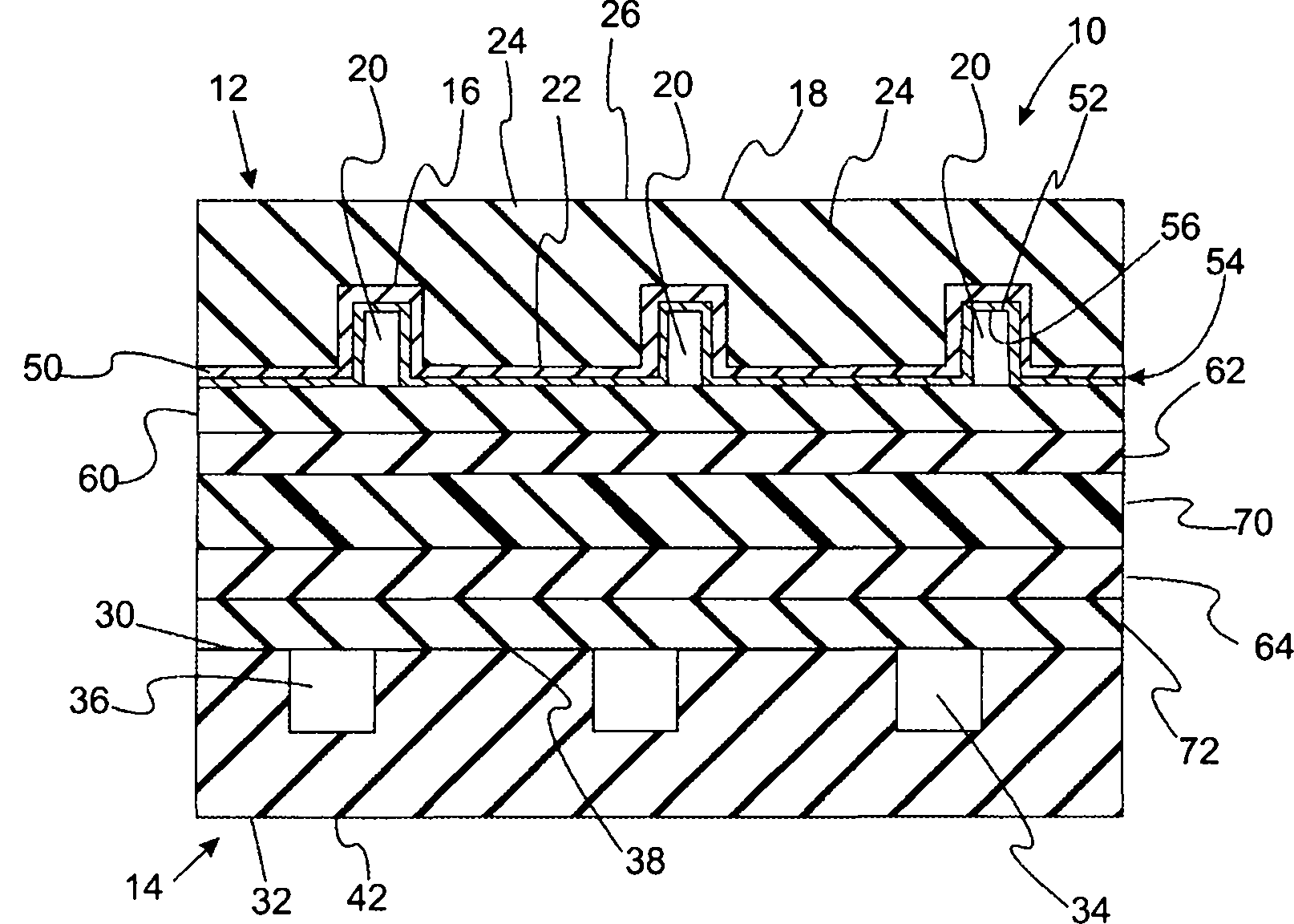
With reference to Figure 1A and Figure 1B, it provides the schematic cross sectional views of the fuel cell of the flow-field plate that includes present embodiment.Fuel cell 10 comprises flow-field plate 12,14.Usually, flow- field plate 12,14 is made by the metal such as stainless steel.Flow-field plate 12 comprises surface 16 and surface 18.Surface 16 limits passage 20 and piston ring land (land) 22.Flow-field plate 12 is unipolar plate in the diagram that Figure 1A provides.Flow-field plate 12 is bipolar plates in the diagram that Figure 1B provides.In this modification, surface 18 defines passage 24 and piston ring land 26.Similarly, flow field 14 comprises surface 30 and surface 32.Surface 30 defines passage 36 and piston ring land 38.Flow-field plate 14 is unipolar plate in the diagram that Figure 1A provides.Surface 32 defines passage 40 and piston ring land 42 in the diagram that Figure 1B provides.
Still with reference to Figure 1A and Figure 1B, carbon-coating 50 is placed on the surface 16 and contact surface 16.Titanium oxide layer 52 is placed on the carbon-coating 50 to form titanium oxide/carbon bilayer 54.Carbon-coating 50 can be unbodied, crystallization or their combination.Usually, the gross thickness of titanium oxide/carbon bilayer 54 is less than 200nm.In another improved, the gross thickness of titanium oxide/carbon bilayer 54 was less than 100nm.In another modification, the gross thickness of titanium oxide/carbon bilayer 54 is greater than about 10nm.In another improved, the gross thickness of titanium oxide/carbon bilayer 54 was greater than about 30nm.In another modification, the gross thickness of titanium oxide/carbon bilayer 54 is to about 80nm from about 20nm.In a modification, titanium oxide/carbon bilayer 54 comprises the surface 56 that has less than the contact angle of about 40 degree.The silane coupler that present embodiment and use contain hydrocarbon produces the art methods of hydrophilic coating and compares, and difference is on the titanium oxide layer amount of being included in the hydrocarbon less than about 40% percetage by weight of this titanium oxide layer total weight.In another improves, on the titanium oxide layer amount of being included in less than the hydrocarbon of about 20% percetage by weight of the total weight of this titanium oxide layer.In another improves, on the titanium oxide layer amount of being included in less than the hydrocarbon of about 10% percetage by weight of the total weight of this titanium oxide layer.In another improves, on the titanium oxide layer amount of being included in less than the hydrocarbon of about 50% percetage by weight of the total weight of this titanium oxide layer.In this linguistic context, term " hydrocarbon " is meant any part (moiety) with hydrocarbon key.
In the modification of present embodiment, titanium oxide/carbon bilayer 54 only is deposited on the wall of passage, and is not deposited on the piston ring land.In another modification, titanium layer only is deposited on the wall of passage, and carbon-coating can be deposited on the piston ring land.
Still with reference to Figure 1A and Figure 1B, fuel cell 10 further comprises gas diffusion layers 60 and catalyst layer 62,64.Polymer ions conductive membranes 70 is between catalyst layer 62 and 64.At last, fuel cell 10 also comprises the gas diffusion layers 72 that is positioned between catalyst layer 64 and the flow-field plate 14.
In modification of the present invention, first gas is introduced in the passage 20, and second gas is introduced in the passage 36.Passage 20 guiding first gas flow, passage 36 guiding second gas flow.In typical fuel cells was used, oxygen-containing gas was introduced in the passage 20, and fuel is introduced in the passage 36.The example of useful oxygen-containing gas comprises molecular oxygen (for example, air).The example of usable fuel is including, but not limited to hydrogen.When oxygen-containing gas is introduced in the passage 20, produce water usually as byproduct, this water must be removed via passage 20.In this modification, catalyst layer 62 is cathode catalyst layers, and catalyst layer 64 is anode catalyst layers.
With reference to figure 2, it provides the amplification view of passage 20.The surface 80,82,84 of titanium oxide layer/carbon bilayer 54 provides the exposed surface in the passage 20.Advantageously, these surfaces of titanium oxide layer/carbon bilayer 54 all are hydrophilic, have the contact angle less than about 40 degree.In another improved, contact angle was less than about 30 degree.In another improved, contact angle was less than about 20 degree.In another improved, contact angle was less than about 10 degree.The hydrophily person's character of titanium oxide layer/carbon bilayer 54 has prevented that water from accumulating in the passage 20.In the improvement of present embodiment, improve the hydrophily of titanium oxide layer/carbon bilayer 54 by activating surface 56 (that is surface 80,82,84,86).In the modification of present embodiment, come activating surface by ultraviolet ray (UV) or plasma (for example, RF plasma, DC plasma, microwave plasma, heated filament plasma, atmospheric plasma (open air plasma), or the like).In an improvement, this activation is by being exposed to titanium oxide layer/carbon bilayer 54 ultraviolet source and realizing, wherein 3 of titanium oxide to 3.2eV low band-gap absorbs ultra-violet radiation and causes electron transition to be arrived in this conduction band, thereby produces the hole in valence band.The photo-catalysis capability of this known titanium oxide under UV activation makes it can not only keep surface hydrophilic, and can also the oxidation organic remains, thereby keeps the permanent cleaning in surface.Therefore, such layer is a hydrolysis-stable under typical fuel cell operating mode.
In another improves, this reprocessing is to realize by titanium oxide/carbon bilayer is exposed to such as nitrogen, nitrous oxide, nitrogen dioxide, ammonia or the such reacting gas of their mixture, and these reacting gass are by break key and form nitrogen radical derivative (as amine, acid amides and diazonium functional group) and activate this titanium oxide layer/carbon bilayer.Therefore, this reprocessing activation energy increases the amount of the nitrogen in titanium oxide layer/carbon bilayer 54.This has further improved the light-catalysed oxidation of titanium oxide in visible-range, and without any need for the UV activation source.In another improved, titanium oxide/carbon bilayer was utilizing nitrogenous gas to handle the back by visible-light activated.In another improved, the activation on surface 56 had caused its porosity (porosity) to compare increase to some extent with the surface before the activation.In further improving, surface 56 comprises the zone that has at least 10 holes in every square centimeter the surface area.And on average, surface 56 comprises at least 5 holes in every square centimeter surface area.By being counted, the number of apertures in the given area of observing calculates every square centimeter number of apertures in the scanning electron microscopy sheet.
The porosity of titanium oxide layer/carbon bilayer 54 also characterizes with the roughness average on surface 56.In a modification, the roughness average on surface 56 is to about 1000nm from about 200nm.In another modification, the roughness average on surface 56 is to about 900nm from about 300nm.In another modification, the roughness average on surface 56 is to about 700nm from about 400nm.
In a modification, carbon-coating of the present invention conducts electricity.The conductance of carbon-coating 50 makes the contact resistance of fuel cell 10 less than about 20mohm-cm
2In the modification of exemplary embodiment, carbon-coating 50 is doped so that increase conductance.In an improvement, carbon-coating 50 is doped.In further improving, alloy is a metal.The example of suitable metalic contamination is including, but not limited to Pt, Ir, Pd, Au, Ag, Co, Fe, Cu, Si, Ti, Zr, Al, Cr, Ni, Nb, Zr, Hb, Mo, W and Ta.In another improved, alloy was nonmetal, for example nitrogen.
With reference to figure 3, its schematic cross sectional views that provides shows the other surface of the fuel battery double plates that is coated with titanium oxide/carbon bilayer.In this modification, surface one or more coated in 18,30 and 32 with carbon-coating 50.As mentioned above, and in conjunction with to the description of Figure 1A and Figure 1B, fuel cell 10 comprises flow-field plate 12,14.Bipolar plates 12 comprises surface 16 and surface 18.Surface 16 defines passage 20 and piston ring land 22.Surface 18 defines passage 24 and piston ring land 26.Similarly, bipolar plates 14 comprises surface 30 and surface 32.Surface 30 limits passage 36 and piston ring land 38.Surface 32 limits passage 40 and piston ring land 42.
Still with reference to Fig. 3, carbon-coating 50 is placed on the surface 16 and contact surface 16.Titanium oxide layer 52 is placed on the carbon-coating 50 to form titanium oxide layer/carbon bilayer 54.In a modification, titanium oxide layer/carbon bilayer 54 comprises the surface 56 that has less than the contact angle of about 40 degree.In an improvement, contact angle is less than 20 degree.In another improved, contact angle was less than 10 degree.Similarly, titanium oxide layer/carbon bilayer 90 is placed on the surface 18 and contact surface 18, and carbon-coating 92 is placed on the surface 30 and contact surface 30, and carbon-coating 94 is placed on the surface 32 and contact surface 32.Fuel cell 10 further comprises gas diffusion layers 60 and catalyst layer 62,64.Polymer ions conductive membranes 70 is between catalyst layer 62 and 64.At last, fuel cell 10 also comprises the gas diffusion layers 72 that is positioned between catalyst layer 64 and the bipolar plates 14.The details of titanium oxide layer/ carbon bilayer 90,92,94 and front are identical in conjunction with the details of titanium oxide layer/carbon bilayer 54 that the description of Figure 1A and Figure 1B is set forth.
With reference to Fig. 4, it provides the cutaway view of the bipolar plate channels that is coated with a plurality of titanium oxide/carbon-coatings.Flow-field plate 12 ' be coated with titanium oxide/ carbon bilayer 54
1, 54
2, 54
3, wherein each all has above about the 54 described designs of titanium oxide/carbon-coating.In this design, layer 50
1, 50
2, 50
3Be carbon-coating, and layer 52
1, 52
2, 52
3It is titanium layer.Usually activated like that as mentioned above from metallic plate titanium oxide/carbon bilayer farthest.Though the concrete example of Fig. 4 comprises three titanium oxides/carbon bilayer, what will be appreciated that is that this modification can comprise two titanium oxides/carbon bilayer.And this modification can also comprise four or more a plurality of titanium oxide/carbon bilayer.
As mentioned above, various embodiment of the present invention comprises one or more titanium oxide layer.The chemical property of titanium character comprises titanium oxide, the amorphous titanium oxide of various crystal forms and has chemical formula TiO
2Material and the low oxide of titanium, the hydrate of titanium oxide and their mixture.The example of crystal form includes but not limited to rutile, anatase and brockite.
With reference to Fig. 5, the diagram flow chart that it provides shows the illustrative methods that forms above-mentioned flow-field plate.In step a), before the deposition of carbon-coating 50, metallic plate 12 is carried out preliminary treatment.Between such pre-treatment period, metallic plate 12 lip-deep oxides are removed usually, perhaps are reduced at least.Such preliminary treatment can comprise cleaning step.In step b), carbon-coating 50 is deposited on the metallic plate 12.Carbon-coating can form by the known many technology of those skilled in the art.The example of such technology includes but not limited to: sputter (for example, magnetron sputtering, the sputter of Nonequilibrium magnetic keyholed back plate or the like), chemical vapor deposition (CVD) (for example, the CVD that low pressure chemical vapor deposition, atmospheric pressure cvd, plasma strengthen, laser assisted CVD or the like), evaporation (thermal evaporation, electron beam evaporation, arc evaporation etc.) or the like.U.S. Patent No. 5,314,716 disclose a kind of CVD technology that is used to form noncrystalline carbon film.By reference whole disclosures of this patent are incorporated at this.In step c), titanium oxide layer 52 is deposited on the carbon-coating 50.Titanium oxide layer can be to form by the known many technology of those skilled in the art.The example of such technology includes but not limited to: sputter (for example, magnetron sputtering, the sputter of Nonequilibrium magnetic keyholed back plate or the like), chemical vapor deposition (CVD) (for example, the CVD that low pressure chemical vapor deposition, atmospheric pressure cvd, plasma strengthen, laser assisted CVD or the like), evaporation (thermal evaporation, electron beam evaporation, arc evaporation etc.), the sol-gel paint-on technique, layer by layer deposition technology, or the like.
In step d), the surface 56 of titanium oxide layer/carbon bilayer 54 is activated.Fig. 5 B show UV activation, visible-light activated and via high-density plasma 100 carry out plasma-activated.What it is also recognized that is to use other activation method.Such method includes but not limited to chemical activation, for example with acid (for example, etching) is handled on this surface, and described acid is sulfuric acid, hydrofluoric acid, chromic acid, potassium permanganate for example, or the like.
In the modification of present embodiment, deposit carbon-coating and titanium oxide layer by sputter.In an improvement, use closed field unbalanced magnetron system to deposit carbon-coating.For this reason, in U.S. Patent No. 6,726, set forth the modification of this method and apparatus in 993 (' 933 patents).By reference whole disclosures of ' 933 patents are incorporated at this.
With reference to Fig. 6, it provides a kind of improvement of the sputtering depositing system that is used to deposit above-mentioned carbon-coating.Fig. 6 provides the schematic top view of this sputtering system.Sputtering system 102 comprises settling chamber 103 and sputtering target 104,106,108,110, and these sputtering targets are near magnet group 112,114,116,118.Characterize the magnetic field that is created between the target 104,106,108,110 with the field wire that extends between the magnetron that forms closed field.This closure field has formed and has prevented to contain the barrier that the electronics in the plasma zone 122 is escaped.And this structure promotes the ionization in the space in closed with the ion bombardment intensity that increases.Thus, realized high ion current density.Substrate 124 (that is, metallic plate 12) is maintained at along direction d
1On the platform 126 of rotation.In the cycle period of platform 126, baffle plate (Flipper) 132 causes that substrate 124 is around direction d
2Rotate.When using system 102, advantageously carry out pre-treatment step a) by in settling chamber 103, carrying out ion(ic) etching.
In a modification of present embodiment, graphite target under non-equilibrium magnetic controlled the influence of closure in the chamber by sputter.A kind of useful sputtering system is Teer UDP 650 systems.Graphite target is placed on the strong magnetron, its can be in closed magnetron arrangement with the electric current of 5A~50A by sputter.Pressure in the sputtering chamber can be 1 * 10
-6To 1 * 10
-4In the scope, bias voltage can be at-400V in-20V scope, pulse duration can 250 nanoseconds in 2000 nano-seconds, the frequency of DC pulse can be at 400KHz in the 50KHz scope, the flow rate of argon gas can be at 200sccm in the 20sccm scope, and continues 10 minutes to 500 minutes time period.In an improvement, come depositing carbon film with the thickness from 5nm to 1000nm.In another modification, come depositing carbon film with the thickness from 10nm to 50nm.Then, exist under the situation of oxygen-containing gas by use the titanium target with the titanium oxide layer sputtering sedimentation on carbon-coating, form above-mentioned titanium oxide/carbon bilayer.After forming titanium oxide layer, in identical sputtering chamber, advantageously carry out the activation of this titanium oxide/carbon bilayer.
Although illustrated and described embodiments of the invention, do not mean these embodiment just illustrate and described of the present invention all may form.On the contrary, the word of Shi Yonging all is illustrative word rather than restricted word in this manual, and it being understood that can make various variations under the situation that does not deviate from the spirit and scope of the present invention.