CN102012307A - Supersonic speed boundary layer wind tunnel - Google Patents
Supersonic speed boundary layer wind tunnel Download PDFInfo
- Publication number
- CN102012307A CN102012307A CN 201010551282 CN201010551282A CN102012307A CN 102012307 A CN102012307 A CN 102012307A CN 201010551282 CN201010551282 CN 201010551282 CN 201010551282 A CN201010551282 A CN 201010551282A CN 102012307 A CN102012307 A CN 102012307A
- Authority
- CN
- China
- Prior art keywords
- boundary layer
- wind tunnel
- supersonic speed
- jet pipe
- tunnel according
- Prior art date
- Legal status (The legal status is an assumption and is not a legal conclusion. Google has not performed a legal analysis and makes no representation as to the accuracy of the status listed.)
- Granted
Links
Images

Landscapes
- Aerodynamic Tests, Hydrodynamic Tests, Wind Tunnels, And Water Tanks (AREA)
Abstract
The invention provides a supersonic speed boundary layer wind tunnel, which comprises a transition section (1), a stabilization section (2) and a nozzle experimental section (3), wherein the transition section (1) is used for introducing air flow and performing first-stage rectification on the air flow; the stabilization section (2) is connected to the downstream of the transition section (1) and is used for performing second-stage rectification on the air flow; the nozzle experimental section (3) is connected to the downstream of the stabilization section (2) and comprises a nozzle part (31), an experimental part (32) and a boundary layer flat plate (33); the nozzle part (31) has a single edge-expanded nozzle structure; a peripheral wall of the experimental part (32) is provided with a transparent window; and the boundary layer flat plate (33) is arranged in an inner chamber of the nozzle experimental section (3), extends into the experimental part (32) from the nozzle part (31), can realize the flow state control of a boundary layer and facilitates implementing optical non-contact testing technology.
Description
Technical field
The present invention relates to a kind of wind-tunnel, relate in particular to a kind of supersonic speed boundary layer wind tunnel.
Background technology
Along with the development of modern aeromechanics technology, the mechanism of aerodynamics Study on Problems is more and more important, and as typical compressible shear flow, the research of supersonic speed boundary layer not only has broad application background but also has the most important theories meaning.Also there is arguement in compressibility to the rule that influences of boundary layer flow field fine structure, and the relation between boundary layer flow field fine structure and the boundary layer dynamic characteristic is still waiting further investigation.The boundary layer in more than 100 year studies show that especially still there is the problem of not seen clearly in a large number in the boundary layer in the supersonic speed boundary layer, in the time of these problem puzzlement fluid mechanics scientific research personnel, also the engineering in boundary layer is used and has been proposed more and more stern challenge.The experimental study in supersonic speed boundary layer is demanded urgently carrying out in a deep going way.
The supersonic speed boundary layer has three-dimensional, non-permanent and multiple dimensioned feature, the constant flow imaging technique is the important means of these features of research, it needs boundary layer wind tunnel to have the good optical measurement environment, and corresponding wind-tunnel optical window need design at the characteristics of research object.
The method that generates from the boundary layer, existing boundary layer empirical model mainly contains two big classes: a class is models such as the flat board in generation boundary layer or circular cone to be put into study in the wind tunnel experiment section, and another kind of is that the boundary layer that directly wind-tunnel wall self is produced is studied.
Article " M.Yoda; J.Westerweel; Particle image velocimetry studies of a boundary layer perturbed by localized suction; Experiments in Fluids.30:239-245; 2001. " has designed a 200mm * 60mm low speed boundary layer flat plate model that is used for FLOW CONTROL research, be installed in the low-speed wind tunnel experimental section, the model lower surface adopts two base fixed supports apart from wind-tunnel wall 70mm.
Two groups of supersonic speed boundary layer experimental studies carried out in article " M.W.Smith; A.J.Smits; Visualization of the structure of supersonic turbulent boundary layers.Experiments in Fluids18:288-302,1995 ".First group of research is to carry out on the bottom blowing type supersonic wind tunnel wall of the 200mm * 200mm of Princeton university, the Experimental Area is apart from nozzle exit 1.9m, and local boundary layer thickness 28mm is 81900 based on the Reynolds number of momentum loss thickness, speed is 580m/s, Mach number 2.82.Other one group of supersonic wind tunnel wall boundary layer that direct research experiment section cross section is 13mm * 26mm, wall at viewing area has optical window, so that the enforcement of optical testing technology, viewing area place boundary layer thickness is 4.2mm, and the Reynolds number that defines based on momentum loss thickness is 25000.
The research of hypersonic boundary layer flow field carried out in article " D.Heitmann et al.; Non-intrusive generation of instability waves in a planar hypersonic boundary layer.Experiments in Fluids; Published online:05 August 2010. ", its boundary layer model is the steel plateform of 630mm * 200mm, the leading edge angle of chamfer is 10 °, the flank of 330mm * 70mm is installed in model front end both sides, to suppress the influence of three-dismensional effect to the boundary layer, whole boundary layer model is installed in the experimental section of HBL hypersonic wind tunnel.
Subject matter based on the boundary layer experiment research of model is: one, the boundary layer leading edge inevitably produces shock wave in the supersonic flow field, can interact with the boundary layer after this shock wave process wall or the free jet edge reflection, produce complicated flow field structure, be unfavorable for the research of boundary layer self fine structure; Two, because wind-tunnel is not to design at boundary layer research institute, corresponding Laboratory Module is generally bigger, is unfavorable for adopting optics non-contact testing technology that the boundary layer fine structure is observed; Three, some blow down wind tunnel Reynolds number is bigger, and the flow field is without noise reduction process, and the commentaries on classics that has a strong impact on the boundary layer is twisted and the unstability characteristic, is unfavorable for mechanism research.
Directly adopt the wind-tunnel wall to produce the boundary layer and study, though overcome the problem that shock wave disturbs, be difficult to adopt optical instrument observation jet pipe internal edges interlayer, this is very disadvantageous to research upstream flow field structure to the influence in boundary layer.In addition, the ratio of width to height of existing wind-tunnel is near 1, and the flow field structure of the serious interference edge interlayer of two side development of boundary layer is unfavorable for mechanism research equally.
Summary of the invention
The technical problem to be solved in the present invention provides a kind of supersonic speed boundary layer wind tunnel, is used for the mechanism research of supersonic speed boundary layer, and boundary layer fluidised form wherein is controlled, and is convenient to the enforcement of optics non-contact testing technology.
For solving the problems of the technologies described above, the invention provides a kind of supersonic speed boundary layer wind tunnel, it is characterized in that comprise: transition section is used to introduce air-flow, and air-flow is carried out first order rectification; Stable section is connected the downstream of transition section, is used for air-flow is carried out second level rectification; And jet pipe experimental section, be connected the downstream of stable section, the perisporium of jet pipe experimental section is formed with transparent window and comprises: spout portion, be configured to monolateral expansion nozzle structure, experiment portion is positioned at the downstream of spout portion and boundary layer flat board, be arranged in the inner chamber of jet pipe experimental section, extend to the experiment portion from spout portion.
Further, above-mentioned supersonic speed boundary layer wind tunnel also comprises diffuser, has the inner-cavity structure that shrinks along towards downstream direction.
Further, the boundary layer is dull and stereotyped for being removably disposed in the jet pipe experimental section.
Further, the xsect of transition section is by the change shape of circular contour to the rectangular profile transition from the upstream extremity downstream end.
Further, the xsect of stable section is rectangular, comprises that the upper perimeter wall that parallels is with lower peripheral wall and be connected upper perimeter wall and two sidewalls of lower peripheral wall.
Further, the xsect of jet pipe experimental section is rectangular, comprises upper perimeter wall with lower peripheral wall and be connected upper perimeter wall and two sidewalls of lower peripheral wall, and the inside surface of upper perimeter wall forms the continuous jet pipe profile curve of one.
Further, the boundary layer flat board is arranged in the jet pipe experimental section by support member, and is positioned at lower peripheral wall top predetermined height.
Further, form an epicoele at the upside of boundary layer flat board, downside forms a cavity of resorption.
Further, the throat of the upstream extremity extend past spout portion of boundary layer flat board and entering in the subsonic speed zone.
Further, the upstream extremity of boundary layer flat board is adapted to the streamline shape of the corresponding jet pipe profile curve in this place and forms the diversion belt that is bent upwards.
Further, diversion belt has transitional surface that is cambered surface or the plane inclination of the outside upstream and the most advanced and sophisticated edge that is positioned at upstream extremity.
Further, the lower peripheral wall of jet pipe experimental section is provided with boundary layer suction outlet, and the boundary layer suction outlet is arranged on corresponding position before the throat with spout portion.
Further, the boundary layer suction outlet extends to the position corresponding with diversion division forward.
Further, the ratio of width to height of jet pipe experimental section is greater than 4.
Further, four perisporiums of the experiment portion of jet pipe experimental section all are formed with transparent window.
Further, transparent window extends to the upstream extremity region of boundary layer flat board forward.
Further, comprise fairing in the stable section, fairing comprises honeycomb and husky net.
Further, the dull and stereotyped optical glass that adopts in boundary layer is made.
The present invention has following technique effect:
1. by in the jet pipe experimental section inner chamber of wind-tunnel, the boundary layer flat board being set, and the spout portion of jet pipe experimental section is configured to monolateral expansion nozzle structure, thereby on the flat board of boundary layer, can generates required boundary layer.Because the shape of boundary layer flat board is convenient to be provided with, by changing the shape and/or the superficial makings (superficial makings that comprises overall region or regional area of boundary layer flat board, bearing of trend of roughness, the picture on surface whether striped or other shapes are arranged, striped or other patterns etc. for example) just can realize that the boundary layer fluidised form is controlled, so that supersonic speed border flow field characteristic is layer by layer studied.In addition, generate the boundary layer by the boundary layer flat board is set, can so that experimental section inside reduce as far as possible or do not have a shock wave.
2. because the perisporium of jet pipe experimental section is formed with transparent window, particularly can all forms transparent window, thereby be convenient to the technology implementation of optics non-contact testing, be convenient to observe the boundary layer flow field form at its four perisporiums.In addition, the boundary layer flat board is preferably made by optical glass, and like this, transparent boundary layer flat board helps the enforcement of optics non-contact testing technology.
3. the ratio of width to height of jet pipe experimental section is set to greater than 4, is preferably greater than 5, connects the influence of the boundary layer of sidewall to the object boundary laminar flow field about can eliminating effectively, to obtain desirable flow field fluidised form.
4. the inside surface of jet pipe experimental section upper perimeter wall forms the continuous jet pipe profile curve of one, like this, a side of monolateral expansion nozzle structure is continuous jet pipe profile curve, and opposite side is controlled boundary layer planar surface, thereby the whole jet pipe wall curvature of face is continuous, helps the whole flow field wave absorption.
5. the upstream extremity of boundary layer flat board is adapted to the streamline shape of the corresponding jet pipe profile curve in this place and forms the diversion belt that is bent upwards, help avoiding the leading edge boundary layer separate bubble to occur, can realize controllable flow field fluidised form, the boundary layer flow field quality better, two-dimensional characteristics is good.By diversion belt being had be transitional surface that the cambered surface or the plane outside upstream tilt and the most advanced and sophisticated edge that is positioned at upstream extremity, further improved the water conservancy diversion characteristic.The boundary layer flat board begins to produce the boundary layer from the subsonic speed section, has avoided the leading edge shock of supersonic speed flat-plate flow.
6. the lower peripheral wall of described jet pipe experimental section is provided with the boundary layer suction outlet, described boundary layer suction outlet is arranged on the position corresponding with the throat of spout portion, quicken in the contraction at this place by throat's suction and air-flow, can reduce the influence that laminar boundary layer is come in the upstream as much as possible.
7. transparent window is extended to the upstream extremity region of described boundary layer flat board forward, can observe and study the formation front and back evolution process of boundary layer flow field so all sidedly.
Except purpose described above, feature and advantage, the present invention also has other purpose, feature and advantage.With reference to figure, the present invention is further detailed explanation below.
Description of drawings
Accompanying drawing is used to provide further understanding of the present invention, constitutes the application's a part, and illustrative examples of the present invention and explanation thereof are used to explain the present invention, do not constitute improper qualification of the present invention.In the accompanying drawings:
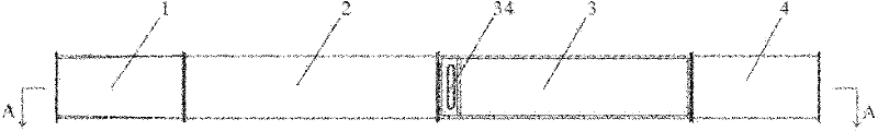
Fig. 1 shows the synoptic diagram of TV structure on the whole of supersonic speed boundary layer wind tunnel of the present invention;
Fig. 2 looks the sectional structure synoptic diagram for the supersonic speed boundary layer wind tunnel among Fig. 1 along the master of A-A position; And
Fig. 3 is the local structure for amplifying synoptic diagram of B portion among Fig. 2.
Embodiment
Below in conjunction with accompanying drawing embodiments of the invention are elaborated, but the multitude of different ways that the present invention can be defined by the claims and cover is implemented.
Referring to Fig. 1, Fig. 2, according to a kind of supersonic speed boundary layer wind tunnel of the present invention, comprise: be positioned at wind-tunnel transition section 1 foremost, be used to introduce air-flow (air-flow can be an airflow, and the difference according to experiment purpose, field, requirement etc. also can adopt other gases), and air-flow carried out first order rectification, make the air-flow that enters wherein form the nowed forming (advection form) that needs; Stable section 2 is connected the downstream of transition section 1, is used for air-flow is carried out second level rectification, makes the air-flow that enters wherein have stable flow characteristics; Jet pipe experimental section 3 is connected the downstream of stable section 2, comprising: spout portion 31, be configured to monolateral expansion nozzle structure, and the air-flow that flows into from stable section 2 is quickened, make wind tunnel experiment portion inlet air flow reach the supersonic speed state; Experiment portion 32 is positioned at the downstream of described spout portion, is used for the space-time structure of the supersonic speed boundary layer flow field that forms such as is observed at experimental study, and the perisporium of experiment portion 32 is formed with transparent window; And boundary layer flat board (for example flat board of optical glass material) 33, be arranged in the inner chamber of described jet pipe experimental section 3, extend to the experiment portion 32 from spout portion 31, be used for matching with the perisporium of spout portion and experiment portion, form the supersonic speed boundary layer flow field.
By in jet pipe experimental section 3 inner chambers of wind-tunnel, boundary layer flat board 33 being set, and the spout portion 31 of jet pipe experimental section 3 is configured to monolateral expansion nozzle structure, thereby on boundary layer flat board 33, can generates required boundary layer.Because the superficial makings of boundary layer flat board 33 is convenient to be provided with, by changing the shape and/or the superficial makings (superficial makings that comprises overall region or regional area of boundary layer flat board 33, bearing of trend of roughness, the picture on surface whether striped or other shapes are arranged, striped or other patterns etc. for example) just can realize that the boundary layer fluidised form is controlled, so that the flow field characteristic in supersonic speed boundary layer is studied.
Transparent window on the perisporium of experiment portion 3 will be formed on experiment portion zone at least.Preferably, can all form transparent window, can observe the boundary layer flow field form easily like this at four perisporiums.Preferably, the material of transparent window is an optical glass, and optical glass also can be arranged on the last lower peripheral wall and sidewall of spout portion 31, so that carry out the enforcement of optics non-contact testing technology.Preferably, transparent window extends to the upstream extremity region of boundary layer flat board 33 forward, can observe and study the formation front and back evolution process of boundary layer flow field so all sidedly.Downstream in combined experiments portion 32 also is connected with diffuser 4, has the inner-cavity structure that shrinks along towards downstream direction.
Enter the stabilized treatment of the air-flow of transition section 1 through stable section 2, send into then in the jet pipe experimental section 3, stable air-flow quickens through spout portion 31, and on boundary layer flat board 33, form the supersonic speed boundary layer, make the flow field in the whole jet pipe experimental section satisfy boundary layer experimental study needs, go in the diffuser 4 in the downstream airflow of boundary layer flat board 33, diffuser 4 is for shrinking pipeline, play the energy-conservation effect of diffusion, to improve the startability of wind-tunnel.
Boundary layer flat board 33 is preferably and is removably disposed in the jet pipe experimental section 3, when the associated shape structure of boundary layer flat board 33 being adjusted in order to satisfy the different experiments needs, can easily mounted boundary layer dull and stereotyped 33 be removed, and the boundary layer flat board 33 that changes the outfit and be adjusted into desired structure, thereby can realize the control of fluid flow, can improve conventional efficient effectively, save time.In addition, the dull and stereotyped preferred optical glass that adopts in boundary layer is made, and the one, can reduce surfaceness, the 2nd, be convenient to probing light illumination flow field.
In the present embodiment, the xsect of the transition section 1 of supersonic speed boundary layer wind tunnel is by the change shape of circular contour to the rectangular profile transition from the upstream extremity downstream end.The porch circular contour can be connected with the circular air outlet of outside blowing device easily.If the air outlet of outside blowing device is a rectangle, then the transition section upstream extremity only need dispose corresponding rectangular profile and gets final product.Transition section 1 is a rectangular profile with the link of stable section 2, can realize being connected with the good of stable section 2.
The xsect of stable section 2 is rectangular, comprises that the upper perimeter wall that parallels with lower peripheral wall and be connected upper perimeter wall and two sidewalls of lower peripheral wall, can adjust the air-flow in the transition section 1, makes stable therein the flowing of gas that enters from transition section 1.The xsect of jet pipe experimental section 3 is rectangular, comprise that upper perimeter wall is with lower peripheral wall and be connected upper perimeter wall and two sidewalls of lower peripheral wall, upper perimeter wall and lower peripheral wall form the continuous jet pipe profile curve of one, like this, one side of monolateral expansion nozzle structure is continuous jet pipe profile curve, opposite side is controlled boundary layer planar surface, thereby the whole jet pipe wall curvature of face is continuous, helps the whole flow field wave absorption.
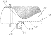
As shown in Figure 3, according to the embodiment of supersonic speed boundary layer wind tunnel of the present invention, boundary layer flat board 23 is arranged in the jet pipe experimental section 3 by support member 332, and is positioned at lower peripheral wall top predetermined height.Support member 332 is arranged on the front end of boundary layer flat board 23, plays support edge interlayer dull and stereotyped 23 and makes it be in the effect of predetermined altitude.Be arranged in the inner chamber of jet pipe experimental section 3 because boundary layer dull and stereotyped 23 is unsettled, extend to the described experiment portion 32 from spout portion 31, like this, the boundary layer is only decided by the boundary layer flat board, can avoid the lower peripheral wall inside surface to generating the influence on flow field of air-flow as much as possible.Upside at boundary layer flat board 23 forms an epicoele 301, and downside forms a cavity of resorption 302.Preferably, the throat of the described spout portion 31 of upstream extremity extend past of boundary layer flat board 23 in the present embodiment and entering in the subsonic speed zone 303, the jet pipe planar wall in the subsonic speed section according to this section ground streamline shape, slightly upwards curved.The upstream extremity of boundary layer flat board 23 is adapted to the streamline shape of the corresponding jet pipe profile curve in this place and forms the diversion belt 331 that is bent upwards, help avoiding the leading edge boundary layer separate bubble to occur, can more help realizing controllable flow field fluidised form, the boundary layer flow field quality better, two-dimensional characteristics is good.Diversion belt 331 has transitional surface that is cambered surface or the plane inclination of the outside upstream and the most advanced and sophisticated edge that is positioned at upstream extremity, when air-flow when stable section 2 enters the jet pipe experimental section 3, further improved the water conservancy diversion characteristic, help avoiding in the classic flat-plate boundary layer interference that dull and stereotyped leading edge shock reflection brings.
As a important improvement (this is one of gordian technique of the present invention) to the embodiment of the invention, the lower peripheral wall of jet pipe experimental section 3 is provided with boundary layer suction outlet 34, boundary layer suction outlet 34 is arranged on the position corresponding with the throat of spout portion 31, quicken in the contraction at this place by throat's suction and air-flow, can reduce the influence that laminar boundary layer is come in the upstream as much as possible.As further improving, boundary layer suction outlet 34 extends in the throat of spout portion 31 position corresponding with diversion division 331 (crossed in the throat the narrowest position of passage arrived the subsonic speed zone) forward, can make air-flow when entering diversion division 331, obtain better acceleration effect, the more important thing is, can also reduce the influence that laminar boundary layer is come in the upstream better.
In the present embodiment, the ratio of width to height of jet pipe experimental section 3 (means the ratio of width to height of passage in the jet pipe experimental section, can recently calculating according to the distance between distance between the sidewall of the left and right sides and the last lower peripheral wall) greater than 4, preferably, its the ratio of width to height is greater than 5, formed thus jet pipe experimental section 3 connects the boundary layer of sidewall to the Boundary Layer on Flat Plate influence on flow field, to obtain desirable flow field fluidised form about can eliminating effectively.
In order to make the air-flow in the stable section 2 have steady flow effect preferably, be provided with fairing 22 in the downstream of stable section 2, fairing 22 comprises honeycomb and husky net.Honeycomb can effectively suppress the horizontal pulsation of incoming flow, and it is the small scale vortex that husky net can make the large scale vortex cracked.The existence of fairing 22, can make the air-flow that flows in the stabilized end 2 more steady, reduce turbulivity, make air-flow can obtain more stable flowing property, can make the suffered interference of flowing gas that enters in the jet pipe experimental section 3 drop to minimum, make experiment obtain effect comparatively accurately.
By foregoing description as can be known, according to supersonic speed boundary layer wind tunnel of the present invention, realize that by the shape and the superficial makings (comprising surfaceness and texture form etc.) that change the boundary layer flat board boundary layer fluidised form is controlled, be convenient to supersonic speed border flow field characteristic is layer by layer studied, connect sidewall boundary layer about can eliminating effectively to the Boundary Layer on Flat Plate influence on flow field, to obtain desirable flow field fluidised form, by the perisporium that optical glass constitutes all is set around experiment portion 32, make it easy to implement optics non-contact testing technology, be convenient to observe the boundary layer flow field form.
The above is the preferred embodiments of the present invention only, is not limited to the present invention, and for a person skilled in the art, the present invention can have various changes and variation.Within the spirit and principles in the present invention all, any modification of being done, be equal to replacement, improvement etc., all should be included within protection scope of the present invention.
Claims (18)
1. a supersonic speed boundary layer wind tunnel is characterized in that, comprising:
Transition section (1) is used to introduce air-flow, and air-flow is carried out first order rectification;
Stable section (2) is connected the downstream of described transition section (1), is used for air-flow is carried out second level rectification; And
Jet pipe experimental section (3) is connected the downstream of described stable section (2), and the perisporium of described jet pipe experimental section (3) is formed with transparent window, comprising:
Spout portion (31) is configured to monolateral expansion nozzle structure,
Experiment portion (32) is positioned at the downstream of described spout portion, and
Boundary layer flat board (33) is arranged in the inner chamber of described jet pipe experimental section (3), extends to the described experiment portion (32) from described spout portion (31).
2. supersonic speed boundary layer wind tunnel according to claim 1 is characterized in that, also comprises diffuser (4), has the inner-cavity structure that shrinks along towards downstream direction.
3. supersonic speed boundary layer wind tunnel according to claim 1 is characterized in that, described boundary layer is dull and stereotyped for being removably disposed in the described jet pipe experimental section (3).
4. supersonic speed boundary layer wind tunnel according to claim 1 is characterized in that, the xsect of described transition section (1) is by the change shape of circular contour to the rectangular profile transition from the upstream extremity downstream end.
5. supersonic speed boundary layer wind tunnel according to claim 1 is characterized in that, the xsect of described stable section (2) is rectangular, comprises the upper perimeter wall that parallels and lower peripheral wall and two sidewalls that are connected described upper perimeter wall and lower peripheral wall.
6. supersonic speed boundary layer wind tunnel according to claim 1, it is characterized in that, the xsect of described jet pipe experimental section (3) is rectangular, comprise upper perimeter wall and lower peripheral wall and two sidewalls that are connected described upper perimeter wall and lower peripheral wall, the inside surface of described upper perimeter wall forms the continuous jet pipe profile curve of one.
7. supersonic speed boundary layer wind tunnel according to claim 6 is characterized in that, described boundary layer flat board (33) is arranged in the described jet pipe experimental section (3) by support member (332), and is positioned at described lower peripheral wall top predetermined height.
8. supersonic speed boundary layer wind tunnel according to claim 7 is characterized in that, forms an epicoele (301) at the upside of described boundary layer flat board (33), and downside forms a cavity of resorption (302).
9. supersonic speed boundary layer wind tunnel according to claim 7 is characterized in that, the throat of the described spout portion of upstream extremity extend past (31) of described boundary layer flat board (23) and entering in the subsonic speed zone (303).
10. supersonic speed boundary layer wind tunnel according to claim 9 is characterized in that, the upstream extremity of described boundary layer flat board (23) is adapted to the streamline shape of the corresponding jet pipe profile curve in this place and forms the diversion belt (331) that is bent upwards.
11. supersonic speed boundary layer wind tunnel according to claim 10 is characterized in that, described diversion belt (331) has transitional surface that is cambered surface or the plane inclination of the outside upstream and the most advanced and sophisticated edge that is positioned at upstream extremity.
12. supersonic speed boundary layer wind tunnel according to claim 10, it is characterized in that, the lower peripheral wall of described jet pipe experimental section (3) is provided with boundary layer suction outlet (34), and described boundary layer suction outlet (34) is arranged on the corresponding position of throat with described spout portion (31).
13. supersonic speed boundary layer wind tunnel according to claim 12 is characterized in that, described boundary layer suction outlet (34) extends to forward and the corresponding position of described diversion division (331).
14. supersonic speed boundary layer wind tunnel according to claim 6 is characterized in that, the ratio of width to height of described jet pipe experimental section (3) is greater than 4.
15. supersonic speed boundary layer wind tunnel according to claim 8 is characterized in that, four perisporiums of the experiment portion of described jet pipe experimental section (3) all are formed with transparent window.
16. supersonic speed boundary layer wind tunnel according to claim 8 is characterized in that, described transparent window extends to the upstream extremity region of described boundary layer flat board (33) forward.
17. supersonic speed boundary layer wind tunnel according to claim 1 is characterized in that, comprises fairing (22) in the described stable section (2), described fairing (22) comprises honeycomb and husky net.
18. supersonic speed boundary layer wind tunnel according to claim 1 is characterized in that, described boundary layer flat board (33) adopts optical glass to make.
Priority Applications (1)
| Application Number | Priority Date | Filing Date | Title |
|---|---|---|---|
| CN2010105512826A CN102012307B (en) | 2010-11-18 | 2010-11-18 | Supersonic speed boundary layer wind tunnel |
Applications Claiming Priority (1)
| Application Number | Priority Date | Filing Date | Title |
|---|---|---|---|
| CN2010105512826A CN102012307B (en) | 2010-11-18 | 2010-11-18 | Supersonic speed boundary layer wind tunnel |
Publications (2)
| Publication Number | Publication Date |
|---|---|
| CN102012307A true CN102012307A (en) | 2011-04-13 |
| CN102012307B CN102012307B (en) | 2012-03-28 |
Family
ID=43842554
Family Applications (1)
| Application Number | Title | Priority Date | Filing Date |
|---|---|---|---|
| CN2010105512826A Active CN102012307B (en) | 2010-11-18 | 2010-11-18 | Supersonic speed boundary layer wind tunnel |
Country Status (1)
| Country | Link |
|---|---|
| CN (1) | CN102012307B (en) |
Cited By (12)
| Publication number | Priority date | Publication date | Assignee | Title |
|---|---|---|---|---|
| CN102840960A (en) * | 2012-08-30 | 2012-12-26 | 华南理工大学 | Method for equalizing wind field of wind tunnel by using Rafah tube |
| CN103234941A (en) * | 2013-04-17 | 2013-08-07 | 中国工程物理研究院流体物理研究所 | Dynamic measurement device and method of material laser reflectivity under subsonic tangential airflow |
| CN103954424A (en) * | 2014-04-30 | 2014-07-30 | 北京大学 | Method for expanding silent test area of hypersonic-velocity silent spray pipe and hypersonic-velocity spray pipe |
| CN104280205A (en) * | 2014-10-24 | 2015-01-14 | 中国人民解放军国防科学技术大学 | Supersonic velocity laminar flow spraying pipe and supersonic velocity quiet wind tunnel thereof |
| CN104359646B (en) * | 2014-10-17 | 2016-09-14 | 北京航天益森风洞工程技术有限公司 | Suction method is used to control the hypersonic nozzle of boundary layer thickness |
| CN106354903A (en) * | 2016-08-18 | 2017-01-25 | 中国人民解放军国防科学技术大学 | Determination method of the computational domain outer boundary for solving the steady circumfluence value of flying objects |
| CN107869498A (en) * | 2016-09-26 | 2018-04-03 | 中国空气动力研究与发展中心高速空气动力研究所 | A kind of supersonic speed Cavity Flow control method based on disturbed motion shock wave |
| CN107870076A (en) * | 2016-09-27 | 2018-04-03 | 中国空气动力研究与发展中心高速空气动力研究所 | A kind of variable boundary thickness degree experimental provision and its application method suitable for Cavity Flow wind- tunnel investigation |
| CN108168831A (en) * | 2017-12-15 | 2018-06-15 | 中国航空工业集团公司沈阳空气动力研究所 | A kind of continuous change Mach number experiment supersonic wind tunnel |
| CN108303227A (en) * | 2018-02-14 | 2018-07-20 | 中国空气动力研究与发展中心高速空气动力研究所 | Aeroelastic effect wind tunnel test half model system and test method |
| CN109827743A (en) * | 2019-04-02 | 2019-05-31 | 重庆科技学院 | A kind of multiple spot multistage adjusting flow-disturbing wedge |
| CN116499686A (en) * | 2023-06-29 | 2023-07-28 | 中国航空工业集团公司沈阳空气动力研究所 | Ground high-speed ejection simulation system and simulation method for wind tunnel test |
Families Citing this family (1)
| Publication number | Priority date | Publication date | Assignee | Title |
|---|---|---|---|---|
| CN108240898A (en) * | 2016-12-23 | 2018-07-03 | 中国航空工业集团公司沈阳空气动力研究所 | A kind of impulse type wind-tunnel tandem jet pipe |
Citations (2)
| Publication number | Priority date | Publication date | Assignee | Title |
|---|---|---|---|---|
| US5713212A (en) * | 1997-02-07 | 1998-02-03 | Mcdonnell Douglas Corporation | Apparatus and method for generating air stream |
| WO2000071956A1 (en) * | 1999-05-21 | 2000-11-30 | Aero Systems Engineering, Inc. | Wind tunnel and heat exchanger therefor |
-
2010
- 2010-11-18 CN CN2010105512826A patent/CN102012307B/en active Active
Patent Citations (2)
| Publication number | Priority date | Publication date | Assignee | Title |
|---|---|---|---|---|
| US5713212A (en) * | 1997-02-07 | 1998-02-03 | Mcdonnell Douglas Corporation | Apparatus and method for generating air stream |
| WO2000071956A1 (en) * | 1999-05-21 | 2000-11-30 | Aero Systems Engineering, Inc. | Wind tunnel and heat exchanger therefor |
Non-Patent Citations (2)
| Title |
|---|
| 《中国博士学位论文全文数据库》 20090715 赵玉新 超声速混合层时空结构的实验研究 全文 1-18 , 第07期 2 * |
| 《西安建筑科技大学学报》 19970930 王元等 风工程学与大气边界层风洞 第344-348页 1-18 第29卷, 第3期 2 * |
Cited By (19)
| Publication number | Priority date | Publication date | Assignee | Title |
|---|---|---|---|---|
| CN102840960A (en) * | 2012-08-30 | 2012-12-26 | 华南理工大学 | Method for equalizing wind field of wind tunnel by using Rafah tube |
| CN102840960B (en) * | 2012-08-30 | 2015-07-01 | 华南理工大学 | Method for equalizing wind field of wind tunnel by using Rafah tube |
| CN103234941A (en) * | 2013-04-17 | 2013-08-07 | 中国工程物理研究院流体物理研究所 | Dynamic measurement device and method of material laser reflectivity under subsonic tangential airflow |
| CN103234941B (en) * | 2013-04-17 | 2015-09-16 | 中国工程物理研究院流体物理研究所 | Material laser reflectivity dynamic measurement device and method under subsonic speed tangential gas flow |
| CN103954424A (en) * | 2014-04-30 | 2014-07-30 | 北京大学 | Method for expanding silent test area of hypersonic-velocity silent spray pipe and hypersonic-velocity spray pipe |
| CN103954424B (en) * | 2014-04-30 | 2016-05-04 | 北京大学 | Expand method and the hypersonic nozzle in hypersonic quiet jet pipe static test district |
| CN104359646B (en) * | 2014-10-17 | 2016-09-14 | 北京航天益森风洞工程技术有限公司 | Suction method is used to control the hypersonic nozzle of boundary layer thickness |
| CN104280205A (en) * | 2014-10-24 | 2015-01-14 | 中国人民解放军国防科学技术大学 | Supersonic velocity laminar flow spraying pipe and supersonic velocity quiet wind tunnel thereof |
| CN106354903A (en) * | 2016-08-18 | 2017-01-25 | 中国人民解放军国防科学技术大学 | Determination method of the computational domain outer boundary for solving the steady circumfluence value of flying objects |
| CN106354903B (en) * | 2016-08-18 | 2019-04-26 | 中国人民解放军国防科学技术大学 | Method is determined for the permanent computational domain outer boundary for streaming numerical solution of aircraft |
| CN107869498A (en) * | 2016-09-26 | 2018-04-03 | 中国空气动力研究与发展中心高速空气动力研究所 | A kind of supersonic speed Cavity Flow control method based on disturbed motion shock wave |
| CN107869498B (en) * | 2016-09-26 | 2019-04-16 | 中国空气动力研究与发展中心高速空气动力研究所 | A kind of supersonic speed Cavity Flow control method based on disturbed motion shock wave |
| CN107870076A (en) * | 2016-09-27 | 2018-04-03 | 中国空气动力研究与发展中心高速空气动力研究所 | A kind of variable boundary thickness degree experimental provision and its application method suitable for Cavity Flow wind- tunnel investigation |
| CN108168831A (en) * | 2017-12-15 | 2018-06-15 | 中国航空工业集团公司沈阳空气动力研究所 | A kind of continuous change Mach number experiment supersonic wind tunnel |
| CN108303227A (en) * | 2018-02-14 | 2018-07-20 | 中国空气动力研究与发展中心高速空气动力研究所 | Aeroelastic effect wind tunnel test half model system and test method |
| CN108303227B (en) * | 2018-02-14 | 2024-04-05 | 中国空气动力研究与发展中心高速空气动力研究所 | Static aeroelastic wind tunnel test semi-model system and test method |
| CN109827743A (en) * | 2019-04-02 | 2019-05-31 | 重庆科技学院 | A kind of multiple spot multistage adjusting flow-disturbing wedge |
| CN116499686A (en) * | 2023-06-29 | 2023-07-28 | 中国航空工业集团公司沈阳空气动力研究所 | Ground high-speed ejection simulation system and simulation method for wind tunnel test |
| CN116499686B (en) * | 2023-06-29 | 2023-08-22 | 中国航空工业集团公司沈阳空气动力研究所 | Ground high-speed ejection simulation system and simulation method for wind tunnel test |
Also Published As
| Publication number | Publication date |
|---|---|
| CN102012307B (en) | 2012-03-28 |
Similar Documents
| Publication | Publication Date | Title |
|---|---|---|
| CN102012307B (en) | Supersonic speed boundary layer wind tunnel | |
| CN102023077B (en) | Supersonic velocity axisymmetrical boundary layer wind tunnel | |
| CN101975653B (en) | Supersonic-speed axisymmetric mixing layer wind tunnel | |
| Zhang et al. | Active drag reduction of a high-drag Ahmed body based on steady blowing | |
| CN102023078B (en) | Supersonic plane mixing layer wind tunnel | |
| US8656957B2 (en) | Vortex generators to control boundary layer interactions | |
| Han et al. | Secondary breakup of axisymmetric liquid drops. II. Impulsive acceleration | |
| CN102023079B (en) | Supersonic free vortex mixing layer wind tunnel | |
| CN101975652B (en) | Ultrasonic-velocity free vortex wind tunnel | |
| US6702233B1 (en) | Airfoil anti-icing assembly and method | |
| Murugan et al. | Shock wave–boundary layer interaction in supersonic flow over a forward-facing step | |
| Eagle et al. | Shock wave–boundary layer interactions in rectangular inlets: three-dimensional separation topology and critical points | |
| CN104908957B (en) | Ridge type scans vortex generator and generation method | |
| EP2969747B1 (en) | Cavity acoustic tones suppression | |
| Sreejith et al. | Experimental and numerical study of laminar separation bubble formation on low Reynolds number airfoil with leading-edge tubercles | |
| CN105730683A (en) | Damping device with vortex damping shell sheets | |
| Issakhanian et al. | In-hole and mainflow velocity measurements of low-momentum jets in crossflow emanating from short holes | |
| Khalighi et al. | Aerodynamic drag reduction investigation for a simplified road vehicle using plasma flow control | |
| Johnston et al. | Vortex generating jets; effects of jet-hole inlet geometry | |
| Munendra et al. | Numerical studies of drag reduction on circular cylinder with V-grooves | |
| GB2514452A (en) | Cavity acoustic tones suppression | |
| Ozgoren et al. | Experimental Investigation of the Flow structure around a sphere and its control with jet flow via PIV | |
| Bourdon et al. | Visualizations and measurements of axisymmetric base flows altered by surface disturbances | |
| Freeborn et al. | Characterization of pylon effects on a scramjet cavity flameholder flowfield | |
| Svensson | A CFD Investigation of a Generic Bump and its Application to a Diverterless Supersonic Inlet |
Legal Events
| Date | Code | Title | Description |
|---|---|---|---|
| C06 | Publication | ||
| PB01 | Publication | ||
| C10 | Entry into substantive examination | ||
| SE01 | Entry into force of request for substantive examination | ||
| C14 | Grant of patent or utility model | ||
| GR01 | Patent grant |