The automatically controlled Semi-automatic lock of three-dimensional locking bolt of three-dimensional locking device and employing electric control operation thereof
Technical field
The present invention relates to a kind of lock, particularly a kind of three-dimensional locking device also relates to the automatically controlled Semi-automatic lock of three-dimensional lock control that above-mentioned three-dimensional locking device adopts electric control operation.
Background technology
At present, electric lock is widely used in people's life, and it generally comprises electronic control module and mechanical locking device, and electronic control module is realized locking and unblanking of electric lock by the action of control locking device.The locking device of existing electric lock is divided into all-electric locking device and half electric locking device, the course of work of these two devices is different, wherein, all-electric locking device is that electronic control module control locking device is directly unblanked, and after half electric locking device unclamped the locking bolt position-limit mechanism by electronic control module before this, open locking bolt by the outer handle of manually operated door again, thereby realize unblanking.Although all-electric locking device can be realized automatically locking and unblanking, and is easy to use, the structure of this kind locking device is more complicated all generally, and manufacturing cost is higher, and power consumption is larger, causes customer group less.
In the prior art, above-mentioned two kinds of locking devices adopt the Unidirectional lock control mode more, namely only at single direction locking bolt is set, as single horizontal locking bolt or single vertical locking bolt be set, although the structure of this kind locking device is simple, because locking bolt only works in one direction, the lock point is less, causes unsafe factor greatly to increase; In recent years, on the basis of Unidirectional lock control mode, progressively developed the locking device that to realize the three-dimensional lock control, this device is to have increased by two to lock control on original Unidirectional lock control basis, when locking, article three, locking bolt can move simultaneously and reach vertical purpose with laterally locking simultaneously, realize multi-faceted locking function, three-way lock prosecutor formula has strengthened door greatly, the security performance of cabinet etc., yet, along with other two setting up to lock control, it is comparatively complicated that the internal construction of locking device also becomes, existing three-way lock control structure generally adopts slide bar; the transmission mechanism of the compositions such as rocking arm is controlled the motion of horizontal and vertical locking bolt; because the component that form increase, greatly improved the manufacturing cost of lock.
Be that 200710078546.9 Chinese invention patent application " electric control lock " discloses a kind of electric control lock such as application number, it comprises the energy-storing flywheel transmission mechanism, hits tongue moment locking mechanism and electric driving mechanism, wherein, the energy-storing flywheel transmission mechanism comprises tooth bar, driver pinion, single direction ratchet, flywheel, unidirectional ratchet, Compress Spring etc.; Hitting tongue moment locking mechanism comprises and hits tongue, roller, hits the tongue bar, hits tongue bar back-moving spring etc.; Electric driving mechanism comprises electromagnet, armature, armature arm-tie etc.This electric control lock is when closing door leaf, and the whole dead bolts on master lock tongue body and the world machine leader and the conduit that is fixed on the master lock tongue body can insert doorframe fully automatically, realize full-automatic locking function.But also there is following defective in this electric control lock: the component of (1) composition locking device are various, and structure is very complicated; (2) because component and mutual matching relationship thereof are all more, cause its manufacturing cost high; (3) need to expend more electric energy; (4) the action matching relationship between each component is comparatively complicated, if one of them parts damages easily causes whole locking device malfunctioning.
Summary of the invention
First purpose of the present invention is to provide that a kind of structure is comparatively simple, the three-dimensional locking device of reliable operation.
First purpose of the present invention realizes by following technical measures: a kind of three-dimensional locking device, comprise box body, laterally locking bolt, vertical locking bolt, be positioned at the locking bolt motion of box body; It is characterized in that described locking bolt motion is gear drive, described gear drive comprises vertical driving member, horizontal driving member, be hinged on the lock core in the box body and be installed in upper on the lock core, lower two gears, described horizontal driving member and vertical driving member all have an inner segment to have rack structure, be respectively applied to described on, lower gear is meshed, they all have one outer section to stretch out outside the box body for connecting respectively horizontal locking bolt and vertical locking bolt, lock core rotates and drives the rotation of two gears, on, lower gear drives respectively horizontal driving member and vertical driving member moving linearly, makes horizontal locking bolt and vertical locking bolt or overhanging or inside contract.
The component of three-dimensional locking device of the present invention are less, and are simple in structure, low cost of manufacture, and the action matching relationship between each component is also comparatively simple, can guarantee the normal operation of whole locking device, and functional reliability is strong.
As one embodiment of the present invention, the gear teeth on the described lower gear are along 1/4th radian settings of gear side circumference, described cogging is a complete gear wheel, the radially wheel face diameter of described lower gear is greater than the radially wheel face diameter that cogs, rack structure on the described horizontal driving member inner segment is meshed with described lower gear, and the rack structure on the described vertical driving member inner segment is meshed with described cogging.Gear drive Range-based between the length that horizontal locking bolt of the present invention stretches out and lower gear, the horizontal driving member.
As a kind of improvement of the present invention, the two-end part that is positioned at described rack structure on the described horizontal driving member inner segment has be used to limiting described horizontal locking bolt overhanging or inside contract the transverse positioning mechanism of ultimate range.
As one embodiment of the present invention, described horizontal driving member is " U " shape structure, it is comprised of two straight sections and a bending segment, described transverse positioning mechanism is positioned at wherein on the straight section, and described transverse positioning mechanism is made of jointly the limited block that is in the above rack structure outer end of this straight section and the inner connecting portion with described bending segment of described rack structure.
As a further improvement on the present invention, described vertical driving member adopts two gear pieces side by side, and the rack structure on these two gear piece inner segments is relative; Described gear piece upper rack structure two-end part has respectively be used to limiting described vertical locking bolt overhanging or inside contract the vertical detent mechanism of ultimate range.The outer end of two gear pieces of the present invention connects a vertical locking bolt separately, forms the three-dimensional locking bolt with horizontal locking bolt.
As one embodiment of the present invention, described vertical detent mechanism adopts limited block, and described limited block is to projecting inward, and the length of protrusion is greater than the length of teeth in the described rack structure.On the overhanging until inner limited block of vertical driving member is stuck in and cogs, to limit the overhanging ultimate range of vertical driving member, otherwise, vertical driving member inside contract until the limited block of outer end be stuck in cog on, the ultimate range that inside contracts to limit vertical driving member, thus prevent vertical driving member and cog disengaging.
Second purpose of the present invention be to provide power consumption that a kind of above-mentioned three-dimensional locking device adopts electric control operation less, the safe automatically controlled Semi-automatic lock of three-dimensional locking bolt easy to use.
Purpose of the present invention realizes by following technical measures: a kind of three-dimensional locking device adopts the automatically controlled Semi-automatic lock of three-dimensional locking bolt of electric control operation, comprise panel, shell and electric control lock, described electric control lock comprises electronic control module and locking device, described panel is provided with knob, it is characterized in that described locking device is the three-dimensional locking device, it comprises box body, horizontal locking bolt, vertical locking bolt and is positioned at the gear drive of box body; Described electric control lock also comprises the electromagnet that is connected with electronic control module, is provided with the position-limit mechanism for spacing described gear drive motion between described gear drive and the electromagnet; Described gear drive comprises vertical driving member, horizontal driving member and is located at the knob back side and stretches into interior upper and lower two gears of box body, described horizontal driving member all has an inner segment to have rack structure with vertical driving member, be respectively applied to be meshed with described upper and lower gear, they all have outer section to stretch out outside the box body for connecting respectively horizontal locking bolt and vertical locking bolt; Electromagnet receives locking or unlocking signal of electronic control module, and position-limit mechanism plays position-limiting action and locks or cancel position-limiting action and make gear drive be in movable state.
The course of work of the present invention is: when unblanking, after electromagnet received the unlocking signal of electronic control module, electromagnet energising iron core shrank, cancel the position-limiting action to gear drive, then, the knob on the manual rotation panel, driven gear rotates, gear drives again horizontal driving member and moves in box body, laterally locking bolt is retracted, and simultaneously, gear matches with vertical driving member and all moves in housing, vertical locking bolt is retracted, thereby the lock control of realization three-dimensional is unblanked; When locking, manual turning knob round about, laterally, vertical locking bolt stretches out and reach latched position, after electromagnet received the upper lock signal of electronic control module, position-limit mechanism played position-limiting action and realizes locking.
As one embodiment of the present invention, described position-limit mechanism comprises spacing hole and pin, described spacing hole is out the vertical cut (V. cut) on described horizontal driving member straight section, described pin is located on the iron core of described electromagnet, described spacing hole to offer the position corresponding with the setting position of described pin; Described electronic control module stretches out and inside contracts by the iron core of control electromagnet, pin inserted or deviate from spacing hole so that stop horizontal driving member motion when locking or when unblanking horizontal driving member be in movable state.
When unblanking, after electromagnet receives the unlocking signal of electronic control module, pin under the iron core of electromagnet drives in suction, at this moment, pin is deviate from spacing hole, cancels the position-limiting action of position-limit mechanism, laterally driving member is in movable state, and this moment, upper and lower gear was rotatable; When locking, horizontal, vertical locking bolt stretches out and reaches latched position, and after electromagnet received the upper lock signal of electronic control module, pin inserted in the spacing hole, stops horizontal driving member motion, and upper and lower gear can't rotate at this moment, thereby realizes locking function.
The present invention has following embodiment, and described box body is docked with top cover by bottom and forms, and described bottom has the chamber of indent, is provided with in this chamber be used to the screens of locating described knob, horizontal driving member and electromagnet; Described horizontal driving member is " U " shape structure, and it is comprised of two straight sections and a bending segment, and described electromagnet and knob all are positioned at the opening of horizontal driving member " U " shape structure.
Be provided with two sliding trays for described horizontal driving member motion in the chamber of bottom of the present invention, two straight sections of described horizontal driving member lay respectively in the described sliding tray, one end of sliding tray is formed for the perforate that the straight section of described horizontal driving member stretches out or inside contracts in the box body side, the relative box body side of described perforate is provided with the strip through hole that stretches out or inside contract for horizontal driving member, and the size of described strip through hole adapts with the lateral length of horizontal driving member.
Compared with prior art, the present invention has following significant effect:
(1) locking device of the present invention adopts gear drive to realize three-dimensional lock control function, carries out the motion of lock control with the transmission mechanism of the compositions such as existing dependence slide bar, rocking arm and compares, and the component of composition greatly reduce, thereby have simplified the structure of locking device.
(2) structure of each component is also relatively simple, is easy to processing and manufacturing, can greatly reduce the manufacturing cost of enterprise.
(3) the present invention adopts the three-dimensional locking device to adopt the automatically controlled Semi-automatic lock of electric control operation, and spent electric energy is less, environmental protection and energy saving, safety easy to use.
(4) the action matching relationship between each component of the present invention is comparatively simple, compares with the locking device of prior art, and functional reliability is strong, and maintenance cost also reduces greatly.
(5) the present invention easily realizes, practicality is stronger, not only can be installed on the cabinet, door body of safe cabinet, also is applicable to the place that other confidentiality is had relatively high expectations.
Description of drawings
The present invention is described in further detail below in conjunction with the drawings and specific embodiments.
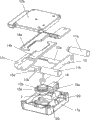
Fig. 1 is structure exploded perspective view of the present invention;
Fig. 2 is the structural representation of the present invention when unblanking;
Fig. 3 is the structural representation of the present invention when locking;
Fig. 4 is the structural representation after Fig. 3 of the present invention removes vertical driving member;
Fig. 5 is that the present invention is installed in the structural representation on the cabinet door.
The specific embodiment
Shown in Fig. 1~5, a kind of three-dimensional locking device of the present invention, comprise box body, laterally locking bolt 11a and 11b, vertical locking bolt 18a and 18b, be positioned at the locking bolt motion of box body; The locking bolt motion is gear drive, gear drive comprises vertical driving member, horizontal driving member, be hinged on the lock core in the box body and be installed in the 12a that cogs on the lock core, lower gear 12b, laterally driving member and vertical driving member all have an inner segment to have rack structure, be respectively applied to and the 12a that cogs, lower gear 12b is meshed, they also all have one outer section to stretch out outside the box body for connecting respectively horizontal locking bolt 11a, 11b and vertical locking bolt 18a, 18b, on lock core rotates and drives, lower gear rotates, on, lower gear drives respectively horizontal driving member and vertical driving member moving linearly, makes horizontal locking bolt and vertical locking bolt or overhanging or inside contract.
A kind of automatically controlled Semi-automatic lock of three-dimensional locking bolt that is adopted electric control operation by above-mentioned three-dimensional locking device, comprise panel, shell and electric control lock, electric control lock comprises electronic control module 1 (referring to Fig. 5) and locking device, panel is provided with knob 2, locking device is above-mentioned three-dimensional locking device 3, and it comprises box body, horizontal locking bolt 11a and 11b, vertical locking bolt 18a and 18b (referring to Fig. 5), is positioned at the gear drive of box body; Electric control lock also comprises the electromagnet 16 that is connected with electronic control module 1, is provided with the position-limit mechanism for the motion of position limited gear transmission mechanism between gear drive and the electromagnet 16; Gear drive comprise vertical driving member, laterally driving member, be hinged on the lock core in the box body and be installed in cog 12a and lower gear 12b on the lock core, lock core adopts knob 2, cog 12a and lower gear 12b is located at the back side of knob 2, laterally driving member all has an inner segment to have rack structure with vertical driving member, be respectively applied to be meshed with the 12a that cogs, lower gear 12b, they also all have one outer section to stretch out outside the box body for connecting respectively horizontal locking bolt 11a, 11b and vertical locking bolt 18a, 18b.
The gear teeth on the lower gear 12b are along 1/4th radian settings of gear 12b side circumference, the 12a that cogs is a complete gear wheel, the radially wheel face diameter of lower gear 12b is greater than the radially wheel face diameter of the 12a that cogs, laterally the rack structure on the driving member inner segment is meshed with lower gear 12b, rack structure on the vertical driving member inner segment is meshed with the 12a that cogs, and laterally driving member is positioned at the below of vertical driving member.
The two-end part that laterally is positioned at rack structure on the driving member inner segment has be used to limiting horizontal locking bolt overhanging or inside contract the transverse positioning mechanism of ultimate range, laterally driving member is " U " shape structure, it is by two straight section 13a, 13b and a bending segment 13c form, transverse positioning mechanism is positioned at wherein on the straight section 13a, in the present embodiment, transverse positioning mechanism is made of jointly the limited block that is in this straight section 13a upper rack structure outer end and the inner connecting portion 12 with bending segment 13c of rack structure, wherein, rack structure is arranged in the upper set depressed part of straight section 13a, and the edge that depressed part and straight section 13a body join namely consists of the limited block 11 of outer end.
Vertical driving member adopts two gear piece 14a, 14b side by side, rack structure on these two gear piece 14a, the 14b inner segment relatively and jointly is engaged on the 12a that cogs, this two gear piece 14a, 14b outer section vertically stretches out box body mutually in the opposite direction is connected with shell and is used for connecting respectively vertical locking bolt 18a, 18b; Gear piece 14a, 14b upper rack structure two-end part has respectively be used to limiting vertical locking bolt 18a, 18b is overhanging or inside contract the vertical detent mechanism of ultimate range, in the present embodiment, vertical detent mechanism adopts limited block 13,14, rack structure is positioned at gear piece 14a, in the set depressed part of 14b, the edge that depressed part and gear piece body join namely consists of limited block 13,14, limited block 13,14 to projecting inward, the length of protruding is greater than the length of teeth in the rack structure, when the overhanging until limited block of gear piece the inner of gear piece contacts with cogging, the overhanging ultimate range of gear piece at this moment, and inside contract until the limited block of gear piece outer end contacts with cogging the ultimate range that inside contracts for gear piece at this moment when gear piece.
Above-mentioned position-limit mechanism comprises spacing hole 13d and pin 16a, and spacing hole 13d is out the vertical cut (V. cut) on horizontal driving member straight section 13b, and pin 16a is located on the iron core of electromagnet 16, spacing hole 13d to offer the position corresponding with the setting position of pin 16a; Electronic control module 1 stretches out and inside contracts by the iron core of control electromagnet 16, pin 16a inserted or deviate from spacing hole 13d so that stop horizontal driving member motion when locking or when unblanking horizontal driving member be in movable state.
Box body is docked with top cover 17b by bottom 17a and forms, and bottom 17a has the chamber of indent, is provided with the screens for positioning knob 2, horizontal driving member and electromagnet 16 in this chamber; Electromagnet 16 and knob 2 all are positioned at the opening of horizontal driving member " U " shape structure.
Be provided with two sliding trays for horizontal driving member motion in the chamber of bottom 17a, laterally two straight section 13a, the 13b of driving member lay respectively in the sliding tray, one end of sliding tray is formed for the perforate 20 that straight section 13a, the 13b of horizontal driving member stretch out or inside contract in the box body side, perforate 20 relative box body sides are provided with the strip through hole that stretches out or inside contract for horizontal driving member, and the size of strip through hole adapts with the lateral length of horizontal driving member.
Also be provided with the junction plate 15 that connects two straight section 13a, 13b in the termination of horizontal driving member two straight section 13a, 13b, this junction plate 15 is positioned at and is used for connecting horizontal locking bolt 11a, 11b outside the box body.
Fig. 5 is that the automatically controlled Semi-automatic lock of three-dimensional locking bolt of the present invention is installed in the structural representation on the cabinet door 10, and wherein, panel is positioned on the front of cabinet door 10, thereby knob 2 is exposed, and shell and electric control lock then all are arranged on the back side of cabinet door 10.
The course of work of the present invention is as follows:
(1) as shown in Figure 2, when unblanking, after electromagnet receives the unlocking signal of electronic control module, pin on the electromagnet is retracted, this moment, pin broke away from spacing hole, and upper and lower gear is in rotating state, got final product the manual rotation knob, make upper and lower gear be rotated counterclockwise 90 °, laterally driving member matches with lower gear horizontal locking bolt is moved in box body, and simultaneously, two vertical locking bolts cooperate with cogging, vertically move in box body round about in the edge, thereby realization three-dimensional locking bolt is all unblanked.
(2) as shown in Figure 3, when locking, the manual rotation knob, make upper and lower gear clockwise rotate 90 °, laterally locking bolt and vertical locking bolt stretch out simultaneously and reach latched position, and after electromagnet received the upper lock signal of electronic control module, the pin on the electromagnet inserted in the spacing hole and realizes locking function; At this moment, because the position-limiting action of pin and spacing hole can't rotate knob.
Electronic control module of the present invention unblank and upper lock signal can be controlled by forms such as password and biological acquisition controllers.
Embodiments of the present invention are not limited to this; according to foregoing of the present invention; ordinary skill knowledge and customary means according to this area; do not breaking away under the above-mentioned fundamental technics thought of the present invention prerequisite; position-limit mechanism of the present invention also has other embodiment; and the limited block in transverse positioning mechanism and the vertical detent mechanism can also be independent parts, so the present invention can also make modification, replacement or the change of other various ways, all drops within the rights protection scope of the present invention.