Vacuum tube (" vacuum tank ") is present the most frequently used coupon.Blood sample normally utilizes the needle tubing of a kind of two ends band tip to extract, and a tip of needle tubing inserts in patient's the blood vessel, and another tip passes in the vacuum tube of pipe close insertion emptying.When this needle tubing coupled together, the pressure differential at two ends impelled blood sample to flow in the vacuum tube.
After sample was extracted out, this vacuum tube generally remained on negative pressure state.If in the laboratory, take off when the sample in the vacuum tube taken out when pipe close, then the pressure equilibrium of moment causes airflow to enter in the vacuum tube, the part sample is ejected, serious risk of infection will be occurred thus, germ might be carried because it has been generally acknowledged that the sample (for example blood sample) in vacuum tube.Handling the lab assistant of handling these samples has the danger of the various diseases infection of being propagated by sample.Therefore, touch with catching that sample is reduced to bottom line and the operation that eliminates danger is very important.
Recommended with [Patent Cooperation Treaty (PCT) patented claim of a kind of pipetting insert, application number WO87/05208] solve this problem, this pipetting insert comprises a fluid catheter that moves that has a tip in its end, when on the pipe close that pipetting insert is placed on vacuum tube, it is pierced through.This moves fluid catheter and has two functions, and first equalized pressure after pipetting insert inserts, makes the pressure in the pipe equal air pressure.Another function is that this moves fluid catheter and can be used as the suction pipe of liquid-transfering device or the leader of syringe needle, extracts sample from vacuum tube.
When the pipe close of pipetting insert by vacuum tube inserts, produce the pressure equilibrium of a moment, if when pressure differential is big, the part sample ejects from pipe, has foregoing risk of infection.
Transfer pipet is by in pipe close one tubular stinger of vacuum tube, and this moves fluid catheter and just is connected with atmospheric environment vacuum tube is inner, promptly sample deposit manage opened.Therefore, when holding coupon, the part sample just overflows from pipe, brings the danger of infection.And the part sample can lose owing to evaporation.
The objective of the invention is to design a kind of pipetting insert that does not have above-mentioned shortcoming.
According to the present invention, the problems referred to above solve by a pipetting insert, and this pipetting insert has following feature:
(a) it is made of plastics,
(b) it has an elongated body, and an end of this body has a tapered segment, has a hollow tip at the other end, and the wall of this tip is pierced through by the liquid-transfering needle head, has an intervalve portion between both ends,
(c) center section of body has a cavity along its longitudinal axis, with the internal communication of the inside and the hollow tip of tapered segment,
(d) outer wall of this body center section comprises the communicating pipe that at least one extends between tapered segment and tip, the cavity cross-section of its sectional area and body center section is long-pending compare much smaller.
The pipetting insert that the present invention proposes has following outstanding advantage:
Because the sectional area of this at least one communicating pipe is quite little, after pipetting insert inserted vacuum tube, the equilibrium phase of pressure was worked as slow, so, in the pressure equilibrium process the phenomenon that the part sample overflows can not appear from vacuum tube.
The pierced through wall of this pipetting insert tip just is pierced when having only the syringe needle by liquid-transfering device to extract sample from pipe.And before this, this vacuum tube is being sealed by the pipetting insert in pipe close and the insertion coupon always, so sample can not overflow from the mouth of pipe fully.Also can not be because of the loss that produces sample of shaking of evaporation or vacuum tube.
For sample is taken out, after pipetting insert being inserted and carry out pressure equilibrium, the cavity of a liquid-transfering needle head by the pipetting insert center section imported and pierces through the wall of pipetting insert tip from vacuum tube.The part sample is entered in the cavity, and stick on the outer wall of liquid-transfering needle head.Just can not occur undesirable part sample yet and " overflow " danger that arrives the syringe needle outer wall.
Above-mentioned various advantage is providing maximum protection to laboratory worker aspect the opposing virus infections.
Pipetting insert of the present invention also is suitable for making as a kind of disposable use device of cheapness.
Below with reference to accompanying drawings various embodiments of the present invention are described, wherein:
Fig. 1 illustrates 13, one pipetting inserts 11 of the present invention of a vacuum tube and a liquid-transfering needle head 19;
Fig. 2 is the upward view according to first embodiment of pipetting insert 11 of the present invention;
Fig. 3 is the cut-open view along III-III line embodiment illustrated in fig. 2;
Fig. 4 is a Fig. 2 and a planimetric map embodiment illustrated in fig. 3;
Fig. 5 is the upward view of second embodiment of pipetting insert 11 of the present invention;
Fig. 6 is the cut-open view along VI-VI line embodiment illustrated in fig. 5;
Fig. 7 is a Fig. 5 and a planimetric map embodiment illustrated in fig. 6;
Fig. 8 is a cut-open view behind Fig. 5 pipetting insert 11 its interior insertion press-on pins pins 41 extremely shown in Figure 7;
Fig. 9 utilizes pressure pin 41 that Fig. 5 is moved the cut-open view that liquid sleeve pipe 11 inserts the process of vacuum tubes 13 pipe closes in embodiment illustrated in fig. 7;
Figure 10 is the cut-open view of representing after pin 41 is removed afterwards in pipetting insert insertion as shown in Figure 9;
Figure 11 is after representing that pipetting insert 11 inserts as shown in Figure 9, the schematic cross-section that its tip 17 has been pierced through by the liquid-transfering needle head 19 that extracts sample;
Figure 12 is the cross-sectional view of Fig. 2 to change type embodiment embodiment illustrated in fig. 4;
Figure 13 is a cut-open view embodiment illustrated in fig. 12, with the size of millimeter (mm) expression;
Figure 14 illustrates the X IV-X IV cut-open view among Figure 13, has provided the size with millimeter (mm) expression.
As shown in Figure 1, pipetting insert 11 of the present invention is as syringe needle 19 and a vacuum tube 13 of liquid-transfering device (not shown in figure 1), for example, blood sample is housed and the Connection Element that undertaken by a pipe close 14 between the vacuum tube of gas-tight seal uses.For example, this blood sample is by its liquid part 12 that is separated from each other and solid portion 28 are formed.For the liquor sample 12 that extracts a specified rate, at first utilize a suitable device of in Fig. 1, not representing that pipetting insert 11 is passed pipe close 14 and insert, enter vacuum tube 13 inside up to its tip.Then, syringe needle 19 is inserted in the vacuum tube 13 by the cavity in the pipetting insert 11 21.The wall of pipetting insert tip is pierced through by syringe needle 19.
These pipetting insert 11 usefulness suitable plastic are made by the injection mould method of forming.This plastics can be kept perfectly harmless in the time of not only will having enough hardness to make pipetting insert 11 pass pipe close, and the tip 17 of this intubate must enough softly make it be easy to pierce through with common liquid-transfering needle head 19 again.For example, a kind of material that is suitable for making pipetting insert 11 is a tygon, and especially high density polyethylene (HDPE) also can be described as low pressure polyethylene (NDPE) or hard tygon.
With reference to Fig. 2 to Fig. 4 first embodiment of pipetting insert 11 of the present invention is described below.Fig. 2 is the upward view of this embodiment.Embodiment shown in Fig. 3 presentation graphs 2 is along the cross-sectional view of III-III line intercepting, and Fig. 4 is the plan view of this embodiment.
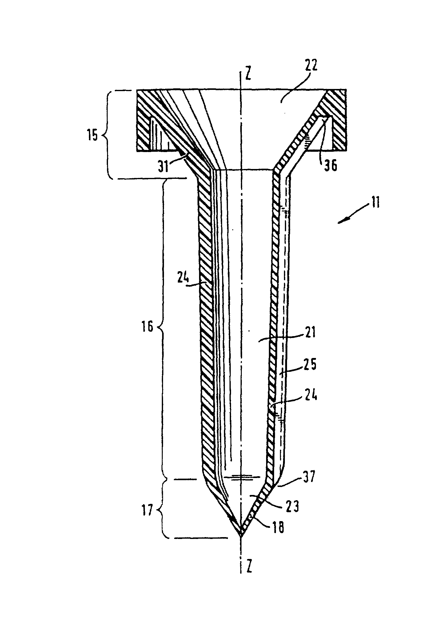
As shown in Figure 3, pipetting insert 11 has an elongated body, and an end of this body has a tapered segment 15, and has a hollow tip 17 at its other end.This tip 17 can constitute by the conical wall 18 that the liquid-transfering needle head pierces through by one.The slender tube body of pipetting insert 11 has an intervalve portion 16 of extending between tapered segment 15 and tip 17.
The intervalve portion 16 of pipetting insert 11 has a cavity 21, and this cavity axis Z-Z along the longitudinal extends and the inside 22 of tapered segment 15 is connected with the inside 23 of hollow tip 17.The intervalve portion 16 of pipetting insert 11 has an outer wall 24, and this outer wall contains the communicating pipe 25 that at least one roughly extends and its sectional area is more much smaller than cavity 21 between tapered segment 15 and tip 17.Have a upper end 36 and a lower end 37 this communicating pipe 25.Pipetting insert 11 preferably has at least two such communicating pipes, and is symmetrical arranged around the longitudinal axis Z-Z of this pipetting insert.
In the embodiment that Fig. 2 to Fig. 4 represents, have three around moving the symmetrically arranged communicating pipe 25,26,27 of longitudinal axis Z-Z that liquid inserts sleeve pipe.
As shown in Figures 2 and 3, each root communicating pipe is to occur with the groove form on the outer wall of outer wall 24 and tapered segment 15.Longitudinal axis Z-Z that the groove that is provided with along the intervalve portion 16 of pipetting insert preferably is roughly parallel to pipetting insert extends.
As following detailed, communicating pipe 25,26,27 are used for the inside of sealed vacuum pipe 13 and the pressure equilibrium between the vacuum tube outside air.Communicating pipe 25,26,27 xsect is made very for a short time, and sample can not overflow from vacuum tube by these communicating pipes when pressure equilibrium.
The thickness of the wall 18 of this pipetting insert tip 17 makes enough thin, so that make it be easy to be pierced through by common liquid-transfering needle head.For example, this wall thickness value shown in Figure 13 is about 0.15 millimeter.
With reference to Fig. 5 to Fig. 7 second embodiment of pipetting insert 11 of the present invention is described below.Fig. 5 is the upward view of this second embodiment.In Fig. 6 presentation graphs 5 along the cross sectional view of this embodiment of VI-VI line intercepting.Fig. 7 is the plan view of this embodiment.
Fig. 5 is extremely embodiment illustrated in fig. 4 to second embodiment shown in Figure 7 and Fig. 2 to be the same substantially, so the front all is applicable to Fig. 5 to Fig. 7 about its major part of description of Fig. 2 to Fig. 4.
Second embodiment that Fig. 5 is extremely shown in Figure 7 and Fig. 2 difference extremely embodiment illustrated in fig. 4 only shows the following aspects:
In a second embodiment, communicating pipe 25,26,27 are extended on the total length of the intervalve portion 16 of pipetting insert.Therefore these communicating pipes are shorter slightly than the communicating pipe of Fig. 2 first embodiment extremely shown in Figure 4.
In a second embodiment, the outer wall of the tapered segment 15 of pipetting insert has at least one extends and have towards the tip fin shape of 17 end 35 along longitudinal axis of this body teat 32.End 35 is than the 36 more close tips 17, upper end of at least one communicating pipe 25, this upper end 36 near tapering parts 15 or be arranged on intervalve portion 16 and tapering part 15 between intersection.
In a most preferred embodiment, the outer wall 31 of tapering part 15 has at least two foregoing teats.As shown in Figure 5, the outer wall 31 of tapering part 15 has three the symmetrically arranged fin shape of the longitudinal axis Z-Z around pipetting insert teats 32,33,34.
Teat 32,33,34 and communicating pipe 25,26,27 all be mutually to be provided with pro rata, thereby guaranteed that desired pressure equilibrium can be by carrying out communicating pipe 25,26,27.
With reference to Fig. 1 and Fig. 8 to Figure 11 the typical usage of pipetting insert 11 of the present invention is described below.Fig. 8 to Figure 11 illustrates Fig. 5 especially to pipetting insert shown in Figure 7, but following description is equally applicable to Fig. 2 to pipetting insert embodiment shown in Figure 4.
In order from vacuum tube 13, to extract the sample 12 of a specified rate, adopted the syringe needle 19 of pipetting insert 11 of the present invention and liquid-transfering device, as shown in Figure 1.
As Fig. 8 and shown in Figure 9, in the preparation process that is sample extraction subsequently, the pipe close 14 that pipetting insert 11 passes vacuum tube 13 is inserted by a suitable device.For this purpose, as shown in Figure 8, at first a pressure pin 41 is inserted in the cavity 21 of pipetting insert 11.The shape of this pressure pin 41 preferably very accurately is matched with the inwall of the upper conical part of pipetting insert 11, the hollow tip of the inwall of cavity and pipetting insert 11 inboards.Pass at pipetting insert 11 before pipe close 14 insertions of vacuum tube 13, will occupy the position shown in Fig. 8 up to it in the pressure pin 41 insertion pipetting inserts.
For pipetting insert 11 is penetrated pipe close 14, with pressure pin 41 facing to the centre of pipe close 14 along the arrow direction with pipetting insert to pressing down, until pipetting insert 11 passes pipe close 14 and occupies position shown in Figure 9.(also be applicable to unshowned teat 33,34 among Fig. 9) as shown in Figure 9, teat 32 plays location effect, guarantees at least one communicating pipe 25 inside of vacuum tube 13 to be connected with the vacuum tube extraneous air, makes pressure equilibrium thus.
Pipetting insert 11 is penetrated after the pipe close 14 in a manner described, pipetting insert 11 remains in the pipe close 14, on the position as shown in figure 10.It is harmless to note that conical wall 18 on the tip 17 of pipetting insert 11 is kept perfectly after inserting pipe close 14, and stops sample to overflow from vacuum tube by cavity 21.
Sample being housed and by position configuration shown in Figure 10 the vacuum tube 13 of pipetting insert 11 being arranged all is airtight container.Therefore they can be used for carrying out various treatment steps, for example, and the centrifugal treating of vacuum tube or stirring, the danger that does not have the part sample to overflow from vacuum tube.
As shown in figure 11,, a liquid-transfering needle head 19 is pressed the cavity 21 that the arrow direction is inserted pipetting insert 11, occupy position shown in Figure 11 up to syringe needle in order from vacuum tube 13, to extract the sample 12 of specified rate.During insertion, the wall 18 of the tip 17 of pipetting insert 11 is pierced through by syringe needle 19.After sample takes out, with syringe needle 19 from vacuum tube 13 or move liquid and insert the sleeve pipe 11 and extract out.Because it is very little to pierce through the aperture of staying on the wall 18,, the part sample is overflowed from vacuum tube if when therefore vacuum tube being carried out normal running.
The change type cross-sectional view of embodiment in Figure 12 presentation graphs 2 to Fig. 4.In this change type, communicating pipe 25,26,27 extend to the top of the tapering part 15 of pipetting insert.
In Figure 13 and Figure 14, embodiment shown in Figure 12 has been marked size with millimeter.Figure 13 represents along the cut-open view of the longitudinal axis of pipetting insert.Figure 14 represents the cut-open view of Figure 13 along X IV-X IV cross section.
The size value major part that provides among Figure 13 and Figure 14 is applicable to that Fig. 2 to Fig. 4 and Fig. 5 are to embodiment shown in Figure 7.
Within the scope of the invention, the scope that some size of pipetting insert can be pointed is below selected:
The one-tenth-value thickness 1/10 of the sidewall 24 of the intervalve portion 16 of pipetting insert 11 is preferably selected between to 1.0 at about 0.3 millimeter.
The thinnest portion one-tenth-value thickness 1/10 of the wall 18 of pipetting insert 11 tips 17 is preferably selected in about 0.1 millimeter to 0.3 millimeter scope.
The mean diameter of the cavity 21 of the intervalve portion 16 of pipetting insert 11 is preferably selected in about 1.5 millimeters to 0.4 millimeter scopes.
Diameter along each communicating pipe 25,26,27 of the outer wall 24 of pipetting insert 11 is preferably selected in about 0.1 millimeter to 0.5 millimeter scope.