CN101951525B - Image processing device, image processing method, and program - Google Patents
Image processing device, image processing method, and program Download PDFInfo
- Publication number
- CN101951525B CN101951525B CN2010102219693A CN201010221969A CN101951525B CN 101951525 B CN101951525 B CN 101951525B CN 2010102219693 A CN2010102219693 A CN 2010102219693A CN 201010221969 A CN201010221969 A CN 201010221969A CN 101951525 B CN101951525 B CN 101951525B
- Authority
- CN
- China
- Prior art keywords
- image
- picture
- stereo
- subject
- data
- Prior art date
- Legal status (The legal status is an assumption and is not a legal conclusion. Google has not performed a legal analysis and makes no representation as to the accuracy of the status listed.)
- Expired - Fee Related
Links
Images


Classifications
-
- H—ELECTRICITY
- H04—ELECTRIC COMMUNICATION TECHNIQUE
- H04N—PICTORIAL COMMUNICATION, e.g. TELEVISION
- H04N19/00—Methods or arrangements for coding, decoding, compressing or decompressing digital video signals
- H04N19/50—Methods or arrangements for coding, decoding, compressing or decompressing digital video signals using predictive coding
- H04N19/597—Methods or arrangements for coding, decoding, compressing or decompressing digital video signals using predictive coding specially adapted for multi-view video sequence encoding
-
- G—PHYSICS
- G11—INFORMATION STORAGE
- G11B—INFORMATION STORAGE BASED ON RELATIVE MOVEMENT BETWEEN RECORD CARRIER AND TRANSDUCER
- G11B27/00—Editing; Indexing; Addressing; Timing or synchronising; Monitoring; Measuring tape travel
- G11B27/10—Indexing; Addressing; Timing or synchronising; Measuring tape travel
- G11B27/19—Indexing; Addressing; Timing or synchronising; Measuring tape travel by using information detectable on the record carrier
- G11B27/28—Indexing; Addressing; Timing or synchronising; Measuring tape travel by using information detectable on the record carrier by using information signals recorded by the same method as the main recording
- G11B27/32—Indexing; Addressing; Timing or synchronising; Measuring tape travel by using information detectable on the record carrier by using information signals recorded by the same method as the main recording on separate auxiliary tracks of the same or an auxiliary record carrier
- G11B27/322—Indexing; Addressing; Timing or synchronising; Measuring tape travel by using information detectable on the record carrier by using information signals recorded by the same method as the main recording on separate auxiliary tracks of the same or an auxiliary record carrier used signal is digitally coded
-
- H—ELECTRICITY
- H04—ELECTRIC COMMUNICATION TECHNIQUE
- H04N—PICTORIAL COMMUNICATION, e.g. TELEVISION
- H04N13/00—Stereoscopic video systems; Multi-view video systems; Details thereof
- H04N13/10—Processing, recording or transmission of stereoscopic or multi-view image signals
- H04N13/106—Processing image signals
- H04N13/128—Adjusting depth or disparity
-
- H—ELECTRICITY
- H04—ELECTRIC COMMUNICATION TECHNIQUE
- H04N—PICTORIAL COMMUNICATION, e.g. TELEVISION
- H04N13/00—Stereoscopic video systems; Multi-view video systems; Details thereof
- H04N13/10—Processing, recording or transmission of stereoscopic or multi-view image signals
- H04N13/106—Processing image signals
- H04N13/161—Encoding, multiplexing or demultiplexing different image signal components
-
- H—ELECTRICITY
- H04—ELECTRIC COMMUNICATION TECHNIQUE
- H04N—PICTORIAL COMMUNICATION, e.g. TELEVISION
- H04N13/00—Stereoscopic video systems; Multi-view video systems; Details thereof
- H04N13/10—Processing, recording or transmission of stereoscopic or multi-view image signals
- H04N13/106—Processing image signals
- H04N13/172—Processing image signals image signals comprising non-image signal components, e.g. headers or format information
- H04N13/178—Metadata, e.g. disparity information
-
- H—ELECTRICITY
- H04—ELECTRIC COMMUNICATION TECHNIQUE
- H04N—PICTORIAL COMMUNICATION, e.g. TELEVISION
- H04N13/00—Stereoscopic video systems; Multi-view video systems; Details thereof
- H04N13/10—Processing, recording or transmission of stereoscopic or multi-view image signals
- H04N13/189—Recording image signals; Reproducing recorded image signals
-
- H—ELECTRICITY
- H04—ELECTRIC COMMUNICATION TECHNIQUE
- H04N—PICTORIAL COMMUNICATION, e.g. TELEVISION
- H04N5/00—Details of television systems
- H04N5/76—Television signal recording
- H04N5/765—Interface circuits between an apparatus for recording and another apparatus
- H04N5/77—Interface circuits between an apparatus for recording and another apparatus between a recording apparatus and a television camera
- H04N5/772—Interface circuits between an apparatus for recording and another apparatus between a recording apparatus and a television camera the recording apparatus and the television camera being placed in the same enclosure
-
- G—PHYSICS
- G11—INFORMATION STORAGE
- G11B—INFORMATION STORAGE BASED ON RELATIVE MOVEMENT BETWEEN RECORD CARRIER AND TRANSDUCER
- G11B2220/00—Record carriers by type
- G11B2220/20—Disc-shaped record carriers
- G11B2220/25—Disc-shaped record carriers characterised in that the disc is based on a specific recording technology
- G11B2220/2537—Optical discs
- G11B2220/2541—Blu-ray discs; Blue laser DVR discs
-
- H—ELECTRICITY
- H04—ELECTRIC COMMUNICATION TECHNIQUE
- H04N—PICTORIAL COMMUNICATION, e.g. TELEVISION
- H04N5/00—Details of television systems
- H04N5/76—Television signal recording
- H04N5/91—Television signal processing therefor
- H04N5/913—Television signal processing therefor for scrambling ; for copy protection
- H04N2005/91307—Television signal processing therefor for scrambling ; for copy protection by adding a copy protection signal to the video signal
- H04N2005/91321—Television signal processing therefor for scrambling ; for copy protection by adding a copy protection signal to the video signal the copy protection signal being a copy protection control signal, e.g. a record inhibit signal
-
- H—ELECTRICITY
- H04—ELECTRIC COMMUNICATION TECHNIQUE
- H04N—PICTORIAL COMMUNICATION, e.g. TELEVISION
- H04N2213/00—Details of stereoscopic systems
- H04N2213/005—Aspects relating to the "3D+depth" image format
-
- H—ELECTRICITY
- H04—ELECTRIC COMMUNICATION TECHNIQUE
- H04N—PICTORIAL COMMUNICATION, e.g. TELEVISION
- H04N5/00—Details of television systems
- H04N5/76—Television signal recording
- H04N5/78—Television signal recording using magnetic recording
- H04N5/781—Television signal recording using magnetic recording on disks or drums
-
- H—ELECTRICITY
- H04—ELECTRIC COMMUNICATION TECHNIQUE
- H04N—PICTORIAL COMMUNICATION, e.g. TELEVISION
- H04N5/00—Details of television systems
- H04N5/76—Television signal recording
- H04N5/84—Television signal recording using optical recording
- H04N5/85—Television signal recording using optical recording on discs or drums
-
- H—ELECTRICITY
- H04—ELECTRIC COMMUNICATION TECHNIQUE
- H04N—PICTORIAL COMMUNICATION, e.g. TELEVISION
- H04N5/00—Details of television systems
- H04N5/76—Television signal recording
- H04N5/907—Television signal recording using static stores, e.g. storage tubes or semiconductor memories
-
- H—ELECTRICITY
- H04—ELECTRIC COMMUNICATION TECHNIQUE
- H04N—PICTORIAL COMMUNICATION, e.g. TELEVISION
- H04N9/00—Details of colour television systems
- H04N9/79—Processing of colour television signals in connection with recording
- H04N9/7921—Processing of colour television signals in connection with recording for more than one processing mode
-
- H—ELECTRICITY
- H04—ELECTRIC COMMUNICATION TECHNIQUE
- H04N—PICTORIAL COMMUNICATION, e.g. TELEVISION
- H04N9/00—Details of colour television systems
- H04N9/79—Processing of colour television signals in connection with recording
- H04N9/80—Transformation of the television signal for recording, e.g. modulation, frequency changing; Inverse transformation for playback
- H04N9/804—Transformation of the television signal for recording, e.g. modulation, frequency changing; Inverse transformation for playback involving pulse code modulation of the colour picture signal components
- H04N9/8042—Transformation of the television signal for recording, e.g. modulation, frequency changing; Inverse transformation for playback involving pulse code modulation of the colour picture signal components involving data reduction
- H04N9/8047—Transformation of the television signal for recording, e.g. modulation, frequency changing; Inverse transformation for playback involving pulse code modulation of the colour picture signal components involving data reduction using transform coding
-
- H—ELECTRICITY
- H04—ELECTRIC COMMUNICATION TECHNIQUE
- H04N—PICTORIAL COMMUNICATION, e.g. TELEVISION
- H04N9/00—Details of colour television systems
- H04N9/79—Processing of colour television signals in connection with recording
- H04N9/80—Transformation of the television signal for recording, e.g. modulation, frequency changing; Inverse transformation for playback
- H04N9/82—Transformation of the television signal for recording, e.g. modulation, frequency changing; Inverse transformation for playback the individual colour picture signal components being recorded simultaneously only
- H04N9/8205—Transformation of the television signal for recording, e.g. modulation, frequency changing; Inverse transformation for playback the individual colour picture signal components being recorded simultaneously only involving the multiplexing of an additional signal and the colour video signal
- H04N9/8227—Transformation of the television signal for recording, e.g. modulation, frequency changing; Inverse transformation for playback the individual colour picture signal components being recorded simultaneously only involving the multiplexing of an additional signal and the colour video signal the additional signal being at least another television signal
Abstract
An image processing apparatus includes: an imaging unit configured to generate an imaged image by imaging a subject; a depth information generating unit configured to generate depth information relating to the imaged image; an image processing unit configured to extract, from the imaged image, an image of an object region including a particular subject out of subjects included in the imaged image and a surrounding region of the subject, based on the depth information, and generate a difference image to display a stereoscopic image in which the subjects included in the imaged image are viewed stereoscopically based on the extracted image; and a recording control unit configured to generate a data stream in which data corresponding to the imaged image and data corresponding to the difference image are correlated, and record the data stream as a moving image file.
Description
Technical field
The present invention relates to image processing equipment, and be specifically related to carry out the image processing equipment processed for the image of the stereovision (stereoscopy) of moving image, image processing method and for making the program of executive program.
Background technology
So far, proposed variously for showing the 3 D image display method of stereo-picture, wherein utilized the parallax of right and left eyes to obtain three-dimensional sense.For example, proposed such 3 D image display method, wherein shown by left eye and watch image and right eye to watch the stereo-picture of image configurations, and three-dimensionally watch this stereo-picture with polaroid glasses.In addition, in recent years, proposed such 3 D image display method, wherein can three-dimensionally watch image, and need not use polaroid glasses.For example, the 3 D image display method as disparity barrier method, biconvex lens method, many view approach (as super many views) etc. has been proposed.
In addition, proposed the imaging device as digital camera and digital camera (integrated the register of camera) etc., it will be view data for the moving picture recording that shows stereo-picture.For example, proposed such optical disk recording device, it will watch image and right eye to watch recording image for the left eye that shows stereo-picture is video flowing (for example, the open No.2008-67393 (Fig. 1) of Japanese Unexamined Patent Application).
Summary of the invention
According to above-mentioned prior art, when playing the moving image of record, the image that forms moving image can sequentially be shown as stereo-picture.For example, yet, in the situation that record is used for utilizing above-mentioned prior art to show the view data of the moving image of stereo-picture,, journal is wherein recorded the left eye of almost identical subject and is watched image and right eye to watch image fully simultaneously.In the situation that such record compares for the view data of plane picture (two dimensional image moving image) with record, the memory space of view data that relates to stereo-picture is large.
Now, in recent years, it is less that the size of imaging device is just becoming, in order to allow the user more easily to carry this device, so the size of the recording medium in imaging device also reduces.For example, may have such situation, wherein the user carries such imaging device at whilst on tour, and the view data that relates to stereo-picture is recorded in each place in travelling.Yet the recording medium in this imaging device usually has the little memory capacity for store various kinds of data.Therefore, can suppose will be shorter for the time quantum of record when record relates to the view data of stereo-picture.Therefore, the storage size that reduces the moving image for showing stereo-picture is important.
Find to have expected suitably to record for showing the moving image of stereo-picture.
According to the embodiment of the present invention, a kind of image processing apparatus comprises: image-generating unit is configured to by subject, imaging generates image; The depth information generation unit, be configured to generate the depth information about described image; Graphics processing unit is configured to: based on described depth information, from described image, extract the image of subject area of the peripheral region of the specific shot body that comprises in the subject that described image comprises and described subject; And the image based on described extraction, generate for showing the difference image of stereo-picture, in described stereo-picture, the described subject of three-dimensionally watching described image to comprise; And record control unit, be configured to generate wherein corresponding to the data of described image and the relevant data flow of data corresponding to described difference image; And described data flow is recorded as to motion pictures files.According to the image processing method of the embodiment of the present invention and for making the program generation effect identical with image processing apparatus of computer carries out image processing method.It has produced following operation: based on depth information, from image, extract the image of subject area of the peripheral region of the specific shot body comprise in the subject that described image comprises and described subject, the image based on described extraction, generate difference image; Generate wherein corresponding to the data of described image and the relevant data flow of data corresponding to described difference image; And described data flow is recorded as to motion pictures files.
Described graphics processing unit can, based on described depth information, determine that the interior subject existed of preset range of the image space of the described image of distance is described specific shot body; Described depth information based on about described specific shot body, determine the described peripheral region on the horizontal direction of described image of described specific shot body; And the image that extracts described subject area from described image.This has produced following effect: determine subject based on depth information, the depth information based on about the specific shot body, determine the peripheral region of horizontal direction of the image of specific shot body, and extract the image of specific region from image.
Described image-generating unit can generate the first image and the second image for showing described stereo-picture, and wherein said depth information generation unit generates the depth information about described the second image; The described depth information of described graphics processing unit based on about described the second image, extract the subject area of the peripheral region of the specific shot body comprise in the subject that described the second image comprises and described subject from described the second image; And the image based on described extraction, generate described difference image; And described record control unit, by will be relevant with the data corresponding to described difference image corresponding to the data of described the first image, generates described data flow.This has produced following effect: generate the first image and the second image, generation is about the depth information of the second image, extract subject area based on described depth information from the second image, image based on extracting generates difference image, and by will be relevant with the data corresponding to difference image corresponding to the data of the first image, generated data stream.
Described record control unit can generate described data flow, and it comprises that indication will comprise the stereo-picture identification information corresponding to the data of described difference image.This has produced the effect that generates the data flow that comprises the stereo-picture identification information.
Described record control unit can, according to the AVCHD standard, generate the described data flow that comprises described stereo-picture identification information in the encapsulation of the modification digital video according to the AVCHD standard.This has produced following effect: in the encapsulation of the modification digital video according to the AVCHD standard, according to the AVCHD standard, generate the described data flow that comprises described stereo-picture identification information
But the moving image management document of the described motion pictures files of described record control unit record management, comprise that indication is included in the stereo-picture identification information in described motion pictures files corresponding to the data of described difference image.This has produced following effect: record the moving image management document, comprise the stereo-picture identification information in described moving image management document.
Described record control unit can be according to the AVCHD standard, the moving image management document that will comprise described stereo-picture identification information be recorded in following one of at least in: index file, clip information file and movie playlist file.This has produced following effect: according to the AVCHD standard, the moving image management document that will comprise described stereo-picture identification information be recorded in following one of at least in: index file, clip information file and movie playlist file.
Described record control unit can generate will corresponding to the data of described image and data corresponding to described difference image and corresponding to the data of described depth information relevant described data flow.This has produced following effect: generation will corresponding to the data of described image and data corresponding to described difference image and corresponding to the data of described depth information relevant described data flow.
Described record control unit can generate the described data flow that comprises depth map presence/absence information, and described depth map presence/absence information indication will comprise the data corresponding to described depth information.This has produced following effect: generate the data flow that comprises depth map presence/absence information.
Described record control unit can, according to the AVCHD standard, generate the described data flow that comprises described depth map presence/absence information in the encapsulation of the modification digital video according to the AVCHD standard.This has produced following effect: according to the AVCHD standard, in the encapsulation of the modification digital video according to the AVCHD standard, generate the described data flow that comprises described depth map presence/absence information.
But the moving image management document of the described motion pictures files of described record control unit record management, comprise that the described motion pictures files of indication comprises the depth map presence/absence information corresponding to the data of described depth information.This has produced following effect: comprise depth map presence/absence information at the moving image management document, and record the moving image management document.
Described record control unit can be according to the AVCHD standard, the moving image management document that will comprise described depth map presence/absence information be recorded in following one of at least in: index file, clip information file and movie playlist file.This has produced following effect: according to the AVCHD standard, the moving image management document that will comprise described depth map presence/absence information be recorded in following one of at least in: index file, clip information file and movie playlist file.
Described record control unit can the growth data zone in the movie playlist file according to the AVCHD standard in, definition is for the registration zone of the playitems playitem of described depth information; And the described playitems playitem of described depth information is recorded in described registration zone.This has produced following effect: in the growth data zone in the movie playlist file according to the AVCHD standard, definition is used for the registration zone of the playitems playitem of described depth information, and the described playitems playitem of described depth information is recorded in described registration zone.
Described image processing apparatus also can comprise: image restoration unit, be configured to the described image and the described difference image that comprise based on described motion pictures files, and recover to form the first image of described stereo-picture; And the stereo-picture generation unit, be configured to the first image and described image based on described recovery, generate described stereo-picture.This has produced following effect: the described image comprised based on described motion pictures files and described difference image, and recovery forms the first image of described stereo-picture; And the first image based on described recovery and described image, generate described stereo-picture.
Described image-generating unit can generate the first image and the second image for showing described stereo-picture, as described image, wherein, described record control unit will be relevant with the second thumbnail image corresponding to described the second image corresponding to the first thumbnail image of described the first image, for showing that the representative image that represents described motion pictures files is as thumbnail image, and be recorded in the moving image management document of the described motion pictures files of management.This has produced following effect: the first thumbnail image is relevant with the second thumbnail image, and the representative image that represents described motion pictures files for demonstration is as thumbnail image, and is recorded in the moving image management document.
Described image processing apparatus also can comprise: indicative control unit, be configured to described the first thumbnail image and described the second thumbnail image based on recording in described moving image management document, and the list of the representative image of the described motion pictures files of Executive Agent shows.This has produced following effect: described the first thumbnail image based on recording in described moving image management document and described the second thumbnail image, the list of the representative image of the described motion pictures files of Executive Agent shows.
It is above-mentioned that to be configured in the moving image aspect that can suitably record for showing stereo-picture be favourable.
The accompanying drawing explanation
Fig. 1 is the block diagram of diagram according to the functional configuration example of the imaging device of first embodiment of the invention;
Fig. 2 A is diagram according to the figure of the internal configurations example of the image-generating unit of first embodiment of the invention and the image that generates by image-generating unit to 2C;
Fig. 3 A is the figure of diagram according to the position relationship of the image-generating unit of first embodiment of the invention;
Fig. 3 B is the figure that illustrates the characteristic example for identifying the subject distance;
Fig. 4 A and 4B are the depth value that is shown in first embodiment of the invention, used by the depth information generation unit when generating depth map and the figure of the relation between the subject distance;
Fig. 5 A to 5C be the depth value that uses when the generating depth map, by the depth information generation unit according to first embodiment of the invention of diagram and subject apart between the figure of relation;
The figure of the position relationship of the subject that Fig. 6 A and the 6B image (left eye) that to be indicative icon generated by the image-generating unit according to first embodiment of the invention and image (right eye) comprise;
Fig. 7 is the depth value of subject of the stereo-picture that generates about the graphics processing unit by according to first embodiment of the invention of diagram and the figure that comprises the relation between the pixel value that records subject area of subject for sign;
Fig. 8 A is to be illustrated schematically according to the graphics processing unit of first embodiment of the invention to generate the figure of the stereoscopic image generation method the situation of three-dimensional difference image from the image (right eye) of imaging to 8F;
Fig. 9 A is the figure be illustrated schematically according to the conversion of graphics processing unit from the situation of image (right eye) the generation stereo-picture of imaging of first embodiment of the invention to 9C;
Figure 10 A and 10B are illustrated schematically according to the record control unit of first embodiment of the invention to generate the figure that the data in the situation of AV stream are processed;
Figure 11 A is the figure of the motion pictures files stored in the memory cell of indicative icon according to first embodiment of the invention;
Figure 11 B is the moving image management document for the management movement image file;
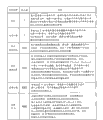
Figure 12 is the type of indicative icon AVCHD file and the associated figure of its effect;
Figure 13 is the figure of the example of the substandard file configuration of diagram AVCHD;
Figure 14 is the figure of the substandard data structure of diagram AVCHD;
Figure 15 A is the figure of the data structure of the substandard common modification digital video encapsulation of diagram AVCHD to 15C;
Figure 16 be diagram AVCHD substandard, comprise the figure with the configuration of the stream file of the data flow of depth map compatibility;
Figure 17 is the figure of the data structure of the substandard index file of diagram AVCHD;
Figure 18 is the figure of the data structure of the substandard play list file of diagram AVCHD;
Figure 19 is the figure of the data structure of the substandard clip information file of diagram AVCHD;
Figure 20 be that indicative icon is recorded in each management document by the record control unit according to first embodiment of the invention, about each the figure of situation of the multi-group data of stereo-picture;
Figure 21 is the flow chart of diagram by the processing procedure of the moving picture recording processing of the execution of the image device according to first embodiment of the invention;
Figure 22 is the block diagram of diagram according to the functional configuration example of the player of first embodiment of the invention;
Figure 23 A is that indicative icon is wherein used three-dimensional master image and three-dimensional difference image to generate the figure of flow process of the Recovery image generation method of Recovery image by the image restoration unit according to first embodiment of the invention to 23C;
Figure 24 is the flow chart of diagram by the processing procedure of the moving image playback process of the execution of the player according to first embodiment of the invention;
Figure 25 is the block diagram of diagram according to the functional configuration example of the image device of second embodiment of the invention;
Figure 26 is the figure of the relation between the pixel value in the depth value of subject of the stereo-picture that generates about the graphics processing unit by according to second embodiment of the invention of diagram and the zone that subject moved to for sign;
To 27C, to be indicative icon generate from image the figure of stereoscopic image generation method that right eye is watched the situation of image according to the graphics processing unit of second embodiment of the invention to Figure 27 A;
Figure 28 is the block diagram of diagram according to the functional configuration example of the image device of third embodiment of the invention;
Figure 29 A is that indicative icon passes through the figure according to the recording processing of the thumbnail image of the record control unit of third embodiment of the invention to 29C; And
Figure 30 A is that indicative icon passes through the figure according to the Graphics Processing of the thumbnail image of the indicative control unit of third embodiment of the invention to 30C.
Embodiment
Use description to carry out embodiments of the invention (being designated hereinafter simply as " embodiment ").To be described in the following sequence.
1. the first embodiment (record controls of stereo-picture: generate the example of motion pictures files that three-dimensional difference image record comprise this solid difference image)
2. the second embodiment (control: the example that generates and show simple stereo-picture) by the demonstration of stereo-picture
3. the 3rd embodiment (record controls of thumbnail image and show to control: for thumbnail image being shown as to the demonstration example that records example and thumbnail image of stereo-picture)
1. the first embodiment
The ios dhcp sample configuration IOS DHCP of imaging device
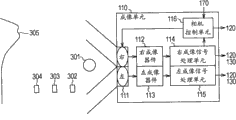
Fig. 1 is the block diagram of diagram according to the functional configuration example of the imaging device 100 of first embodiment of the invention.Imaging device 100 comprises image-generating unit 110, depth information generation unit 120, graphics processing unit 130, image encoder 140, depth information encoder 150, record control unit 160, operation acceptance unit 170 and memory cell 200.
Image-generating unit 110 is the image-generating units that can process the stereovision imaging, it is according to the operation from operation acceptance unit 170 inputs, by imaging generates two images (view data) to subject, and the image of two generations is outputed to depth information generation unit 120 and graphics processing unit 130.Two images are for showing stereo-picture, for the image (left eye is watched image) of left eye with for the image (right eye is watched image) of right eye.Image-generating unit 110 also outputs to depth information generation unit 120 by the position of each lens and focal position.Note, describe the internal configurations of image-generating unit 110 with reference to Fig. 2 in detail.
Depth information generation unit 120 generates the depth map about two images from image-generating unit 110 outputs, and the depth map of generation is outputed to graphics processing unit 130 and depth information encoder 150.In addition, depth information generation unit 120 has also generated the depth map information generated about the depth map of image to record control unit 160 output indications.Note the data of the degree of depth (that is, subject distance) of the subject of depth map being indication from the image space position of imaging device 100 (that is, from) to image.The example that can be used for the technology of generating depth map comprises TOF (flight time) and defocuses analysis (apart from the degree of depth defocused).For example, TOF is such technology, wherein by reflection, from light source, is transmitted into the distance of the photo measure of subject apart from subject, and delay and the light velocity of the light based on arriving transducer, calculates this distance.Note, below with reference to Fig. 3, describe the method for the generating depth map of the first embodiment in detail.
The depth map of graphics processing unit 130 based on from 120 outputs of depth information generation unit, according to the operation from operation acceptance unit 170 inputs, the three-dimensional difference image of one of two images that generation is exported from image-generating unit 110.Then graphics processing unit 130 exports another image (that is, exporting three-dimensional master image) of the three-dimensional difference image generated and two images exporting from image-generating unit 110 to image encoder 140.In addition, in the situation that generated three-dimensional difference image and three-dimensional master image, graphics processing unit 130 outputs to record control unit 160 by the stereo-picture information generated.It should be noted that three-dimensional difference image is for showing the image of stereo-picture, and can generate original image by using three-dimensional master image.Note, describe the generation of stereoscopic parallax image with reference to Fig. 6 A to 9C in detail.
Three-dimensional master image and three-dimensional difference image (that is, digital of digital video data) that image encoder 140 codings are exported from graphics processing unit 130, and three-dimensional master image and the three-dimensional difference image of coding are outputed to record control unit 160.For example, image encoder 140, according to predetermined compaction coding method, is carried out from the compressed encoding of the digital of digital video data of graphics processing unit 130 outputs, and the digital of digital video data of compressed encoding is provided to record control unit 160 flows as AV.In the situation that the present embodiment, in the situation that adopt AVCHD standard movement recording image form, the situation of the H.264/MPEG-4 AVC that use can high efficient coding is as the moving picture experts group method.In the situation that use the method, for example, by prediction in DCT (discrete cosine transform) and screen, carry out compression in frame.Thereby, carry out compression in the frame that uses motion vector, in addition, carry out entropy and encode to improve compression efficiency.For three-dimensional master image and three-dimensional difference image, the image synchronous processing of experience (being known as genlock).In addition, when coding, provide identical PTS (presentative time stamp) to three-dimensional master image and three-dimensional difference image from graphics processing unit 130 outputs.PTS is for timestamp synchronous when the playing moving images.
The depth map that depth information encoder 150 codings are exported from depth information generation unit 120, and the depth map of coding is outputed to record control unit 160.For example, depth information encoder 150, according to predetermined compaction coding method, is carried out from the compressed encoding of the numerical data of depth information generation unit 120 outputs, and the numerical data of compressed encoding is provided to record control unit 160 flows as AV.
Record control unit 160 utilizes from the AV stream of image encoder 140 outputs and flows from the AV of depth information encoder 150 outputs, and is multiplexed with single AV stream according to preordering method by these two, and is recorded in memory cell 200 as motion pictures files.For example, the multiplexing AV stream of record control unit 160, and multiplexing AV stream is stored in the stream damper of present.For example, in the situation that adopt AVCHD standard movement recording image form, obey MPEG-2TS (transmitting stream) and carry out multiplexing.Record control unit 160 monitors the data volume of storing in stream dampers, and the predetermined amount of data of storing in stream damper or when more, reads the record cell for the data volume of memory cell 200 from stream damper, and it is write to memory cell 200.That is to say, record control unit 160 forms the motion pictures files of the AV stream of storing in stream damper, and it is stored in memory cell 200.In addition, the stereo-picture information generated of record control unit 160 based on from graphics processing unit 130 outputs and the depth map information generated of exporting from depth information generation unit 120, be included in stereo-picture identification information and depth map presence/absence information in AV stream.With the same manner, record control unit 160 is included in stereo-picture identification information and depth map presence/absence information in the moving image management document and is recorded in memory cell 200.Below with reference to Figure 10 A to these recording methods of 20 detailed descriptions.
The example of the ios dhcp sample configuration IOS DHCP of image-generating unit and generation image
Fig. 2 A is diagram according to the figure of the example of the example of the internal configurations of the image-generating unit 110 of first embodiment of the invention and the image that generated by image-generating unit 110 to 2C.Relation between Fig. 2 A indicative icon imaging device 100 and the subject of watching from the side.The example of the relation between the subject under the state in Fig. 2 B indicative icon imaging device 100 and Fig. 2 A of watching from above and the internal configurations of image-generating unit 110.The example of the image that Fig. 2 C diagram generates by the layout shown in Fig. 2 A and 2B.In this example, generate two images, wherein people 301, placard 302 to 304 and the mountain 305 of from ground, erectting are subjects simultaneously.
In the example shown in Fig. 2 A, will think that the zoom position of lens unit 111 of imaging device 100 is in wide-angle side.In the case, the 0.5m that people 301 and placard 302 and 303 are present in apart from imaging device 100 (specifies subject Extraction parts 306) in the scope of 5.0m, wherein the most easily feels the third dimension caused due to the parallax in picture.On the other hand, placard 304 and mountain 306 are positioned at the subject distance over the scope of 5.0m.
As shown in Fig. 2 B, image-generating unit 110 comprises lens unit 111, right image device 112, left image device 113, right imaging signal processing unit 114, left imaging signal processing unit 115 and camera control unit 116.Now, configuration image-generating unit 110, make each for the left side and the right that lens, image device and the imaging signal processing unit of lens unit 111 are provided, for each as one group, in order to generate for showing that the right eye of stereo-picture watches image and left eye to watch image.In Fig. 2 B, utilize image-generating unit 110, for generating right eye, watch the lens of the lens unit 111 of image to be marked with word " right side " at ellipse.For generating right eye, watch the image device of image and each of imaging signal processing unit to be depicted as right image device 112 and right imaging signal processing unit 114.On the other hand, for generating left eye, watch the lens of the lens unit 111 of image to be marked with word " left side " at ellipse.For generating left eye, watch the image device of image and each of imaging signal processing unit to be depicted as left image device 113 and left imaging signal processing unit 115.Note, the configuration of the left and right lens of lens unit 111, right image device 112 and left image device 113 and right imaging signal processing unit 114 and left imaging signal processing unit 115 is identical, except it is arranged.Therefore, in the following description, one of left and right configuration will be described, and the description that will omit another.
Right imaging signal processing unit 114 is that the picture signal from right image device 112 outputs is carried out to the right eye imaging signal processing unit that various signals are processed.In addition, left imaging signal processing unit 115 is that the picture signal from left image device 113 outputs is carried out to the left eye imaging signal processing unit that various signals are processed.The picture signal (view data) that the experience signal is processed outputs to camera control unit 116 and graphics processing unit 130.Describe the image generated by right imaging signal processing unit 114 and left imaging signal processing unit 115 in detail with reference to Fig. 2 C.
Image shown in Fig. 2 C (left eye) the 311st, the image (left eye is watched image) of the picture signal of exporting corresponding to the left imaging signal processing unit 115 from state shown in Fig. 2 A and 2B.In addition, the image shown in Fig. 2 C (right eye) the 312nd, the image (right eye is watched image) of the picture signal of exporting corresponding to the right imaging signal processing unit 114 from this state.In the situation that first embodiment of the invention, generate the three-dimensional difference image about image (right eye) 312, and this solid difference image and image (left eye) 311 are recorded as for showing the motion pictures files of stereo-picture.Note, describe the generation of three-dimensional difference image with reference to Fig. 6 A to 9C in detail.
The example of generating depth map
Next, describe with reference to the accompanying drawings the degree of depth drawing generating method of the depth map for generating the image generated by image-generating unit 110 in detail.At first, use when being described in generating depth map, for calculating the method for the distance (subject distance) between imaging device 100 and subject.
Fig. 3 A is the figure of diagram according to the position relationship of the image-generating unit 110 of first embodiment of the invention, and Fig. 3 B is the figure that illustrates the example of the character curve for identifying the subject distance.Lens unit 111 comprises Zoom lens unit 180, aperture 183, fixed lens 184, vibration of optical correcting lens 185 and condenser lens 186.In addition, Zoom lens unit 180 has zoom lens 181 and light path folding prism 182.In addition, provide the imaging surface of filter 187 to right image device 112.Note, in Fig. 3 A, simplified a plurality of lens that are provided to lens unit 111, only show lens 181 and 184 to 186.
The example of the character curve of the relation between the position of Fig. 3 B diagram expression subject distance, zoom lens 181 and the position of condenser lens 186.In the curve chart shown in Fig. 3 B, vertical axis means the position of condenser lens 186, and trunnion axis means the position of zoom lens 181.Particularly, in the situation that vertical axis, upside is nearside, and downside is (infinity) side far away.In addition, in the situation that trunnion axis, left side is that wide-angle is distolateral, and right side be dolly-out, dolly-back distolateral.Note, these character curves are different between the lens for imaging device.In the situation that first embodiment of the invention, depth information generation unit 120 keeps these character curves.
Curve L1 shown in Fig. 3 B is the position for the position based on zoom lens 181 and condenser lens 186, the subject of sign focusing and the curve of the subject distance between imaging device 100 to L4.Note, the example in Fig. 3 B illustrates four character curve L1 to L4, wherein the subject distance respectively at 0.8m in the scope of infinity (∞), and in figure omission corresponding to the character curve of other subject distances.As shown in Figure 3 B, in the situation that obtained the position of zoom lens 181 and condenser lens 186, can obtain the subject distance about the subject in now focusing on.
The figure of the relation between the depth value used when Fig. 4 A and 4B are the depth map illustrated in generating first embodiment of the invention, by depth information generation unit 120 and subject distance.In Fig. 4 A, the relation between subject distance and depth value illustrates with table format, and, in Fig. 4 B, the relation between subject distance and depth value illustrates with the curve chart form.Now, as shown in Fig. 4 A and 4B, depth value is from 0 to 255 the value of determining according to subject distance.In addition, depth map is definite depth value and the location of pixels correspondingly relevant information (depth information) to each pixel that forms image wherein.The subject distance of each subject of using depth map to allow the estimation image to comprise.
Now, will be described about the depth of field.Depth of field diagram is thought the subject scope of the subject distance in focusing on substantially.Usually, in the situation that this wide ranges, the depth of field is large, and in the situation that this narrow range, the depth of field is little.Usually also understand, the depth of field changes according to the aperture of aperture.For example, aperture is larger, and the corresponding depth of field is less, and aperture is less, and the corresponding depth of field is larger.
For example, in the situation that the aperture of the aperture 183 shown in Fig. 3 A arranges relatively littlely, the subject on the optical axis of imaging device 100 on the relatively wide scope of (the far and near direction on optical axis) is in focusing on.On the other hand, in the situation that the aperture of aperture 183 is opened relatively widely, if the subject in areas imaging a little near or away from the optical axis of imaging device 100, they may be in not focusing on.That is to say, in the situation that the depth of field is little, subject only in the relatively narrow scope of the far and near direction about on optical axis in focusing on.
With first embodiment of the invention accordingly, the situation of compute depth value will be described as the example of using above-mentioned subject depth attribute.
At first, by the example that is described in while starting imaging operation, zoom lens 181 are arranged on compute depth value under the distolateral state of wide-angle.For example, it is distolateral that zoom lens 181 are arranged on wide-angle, and aperture 183 opens widely, makes depth of field minimum.In this way in the situation that zoom lens 181 are arranged on the distolateral depth of field minimum that makes of wide-angle, make and think the narrow range of the subject distance of subject in focusing on.Under the state of the little depth of field, condenser lens 186 is set to distally (infinite distally, that is,>5m).In the situation that the depth of field is set to minimum and condenser lens 186 is set to distally, detect the focal zone of image.Useful high fdrequency component and low frequency component feature etc. determine whether to exist and focus on.For example, can detect contrasting signal from image, and the amplitude of the signal level of contrasting signal can be used to determine whether exist focusing.For example, in the situation that the signal level of contrasting signal is high, can determines and realize focusing on (high degree of focus), and, in the situation that the signal level of contrasting signal is low, can determine and focus on (low degree of focus).
Therefore, can estimate to be present in relatively the position away from imaging device 100 when the depth of field is made as when minimum and condenser lens 186 are made as distally the subject comprised in focusing range.The subject distance of the subject that for example, this zone comprises can be used the curve chart shown in Fig. 3 B (character curve L4) sign.120 pairs of depth information generation units identify thus the pixel that the zone of its subject distance comprises and distribute depth value " 0 ".
Next, in the situation that the depth of field is made as is minimum, condenser lens 186 is made as nearside (0.5m), detects the focal zone of image.The depth of field is made as minimum and condenser lens 186 is located at nearside, and detect in image to be processed and realize the zone focused on.Therefore, can estimate that subject that the focusing range when the depth of field is made as minimum and condenser lens 186 and is located at nearside comprises is present in relatively the position near imaging device 100.For example, the character curve shown in the curve chart of use Fig. 3 B, the subject distance of the subject that this zone comprises can be designated minimum distance (0.5m).120 pairs of depth information generation units identify thus its subject distance and distribute depth value " 255 " for the pixel that the zone of minimum distance (0.5m) comprises.
Next, in the depth of field, be made as under minimum state, condenser lens 186 moves to distally from nearside, detects the focal zone in the image of each position of condenser lens 186 simultaneously.The subject distance in the zone of detecting is by the sign of the curve chart in Fig. 3 B, and depth information generation unit 120 distributes the depth value (0 to 255) of obeying the relation shown in Fig. 4 A and 4B.Next, the depth value generating depth map that depth information generation unit 120 each pixel based on about forming image obtains, and the depth map of generation is outputed to graphics processing unit 130 and depth information encoder 150.
Therefore, when starting imaging operation, depth map is carried out to initial setting up.After initial setting up, the subject that 120 pairs of images that generated by image-generating unit 110 of depth information generation unit comprise is carried out the profile identifying processing, and the zone sequence in the profile of identification is distributed to depth value.This profile identifying processing can be based on image be comprised the motion vector of detection of each subject carry out.Therefore, can be to each frame generating depth map of the moving image that forms imaging.
Described above about when starting imaging operation, in the situation that zoom lens 181 are located at the example of wide-angle side compute depth value.Now, probably there is such situation, wherein when starting imaging operation, by the user, operate the execution zoom operation.For example,, in the situation that the people who is given a lecture from wide-long shot, when starting imaging operation, will often operate the execution zoom operation by the user.Can imagine the stereo-picture that may want to watch from the moving image of the imaging of record in this way the people who provides speech.Yet, in the situation that record in this way image, zoom lens 181 start to be positioned at the end of dolly-out,ing dolly-back, so now unavailable for the said method of generating depth map.Now, description zoom lens 181 when starting imaging operation are positioned to the example of compute depth value under the state in addition of wide-angle side position.
Fig. 5 A is that diagram is when the generating depth map, by the subject distance of depth information generation unit 120 uses according to first embodiment of the invention and the figure of the relation between depth value to 5C.Fig. 5 A is shown in zoom lens 181 in the situation that the curve chart of the subject distance of the ZL1 on the trunnion axis on the curve chart shown in Fig. 3 B and the relation between depth value.Fig. 5 B is shown in zoom lens 181 in the situation that the curve chart of the subject distance of the ZL2 on the trunnion axis on the curve chart shown in Fig. 3 B and the relation between depth value.Fig. 5 C is shown in zoom lens 181 in the situation that the curve chart of the subject distance of the ZL3 on the trunnion axis on the curve chart shown in Fig. 3 B and the relation between depth value.In the curve chart shown in Fig. 3 B, point to and be illustrated schematically in the focusing range of the condenser lens of each position of placing zoom lens 181 corresponding to ZL1 to the thick arrow of the position of the line of ZL3.In addition, although Fig. 5 A only illustrates three pattern K2 to K4 to 5C, yet can, by keeping four or multi-mode more, to various arrangements, obtain depth values.
Therefore, even, in the situation that zoom lens 181 are positioned at the position beyond wide-angle side, also can distribute depth value, even make when starting imaging operation zoom lens 181 be positioned at the position beyond wide-angle side, but also generating depth map.
As mentioned above, to the image generating depth map of each imaging.In the situation that first embodiment of the invention, the depth map generated in this way watches image and right eye to watch the overlapping region of image for identifying left eye, to watch image from right eye, generates three-dimensional difference image, and records this solid difference image and left eye is watched image.
Generate the example of three-dimensional difference image
Fig. 6 A and 6B are the figure of indicative icon by the position relationship of image (left eye) 311 of image-generating unit 110 generations according to first embodiment of the invention and the subject that image (right eye) 312 comprises.Note, (left eye) 311 of the image shown in Fig. 6 A and image (right eye) 312 are identical with those shown in Fig. 2 C.
Fig. 6 B illustrates overlapping state of (left eye) 311 of the image shown in Fig. 6 A and image (right eye) 312.Note, in the example shown in Fig. 6 B, image (left eye) 311 illustrates with thick line with the relative large subject of alternate position spike in image (right eye) 312.In these thick lines, the profile of the subject that image (right eye) 312 comprises (, people 301 and placard 302 and 303) by heavy line, indicated, and the subject that image (left eye) 311 comprises (that is, people 301 and placard 302 and 303) is indicated with thick dashed line.
Now, in the subject zone that two images of same time dot generation comprise, 0.5m for example is present in the position near imaging device 100 to the subject part comprised in the scope of 5.0m, and therefore horizontal level is often different.On the other hand, 5.0m for example is present in the position away from imaging device 100 to the subject part comprised in the scope of ∞, so horizontal level is often roughly the same.For example, as shown in Figure 6B, in the subject that image (left eye) 311 and image (right eye) 312 comprise, 0.5m is mutually different to the position (that is, people 301 and placard 302 and 303) of the subject comprised in the scope of 5.0m.That is to say, in the situation that image (left eye) 311, people 301 in image is relative with 303 position with placard 302 to be positioned at towards the right, and in the situation that image (right eye) 312, the people 301 in image is relative with 303 position with placard 302 to be positioned at towards the left side.
On the other hand, in the subject that image (left eye) 311 and image (right eye) 312 comprise, 5.0m has roughly the same position to the position of the subject (placard 304 and mountain 305) in the scope of ∞ in image.That is to say, expectation by use one of image (left eye) 311 and image (right eye) 312 and by as subject zone closely by thick line (solid line and dotted line) around self zone, another image can revert to and original roughly the same image.
Therefore, in the situation that first embodiment of the invention, we will adopt and be recorded in one of two images of same time dot generation (for example, image (left eye) 311) as three-dimensional master image.For another image (for example, image (right eye) 312), the common region of the subject part that sign comprises to the image in the scope of ∞ as 5.0m, and the part of this another image not to be covered (image (right eye) 312) in this common region (that is, being arranged in closely its part in subject zone) is recorded as three-dimensional difference image.When recording this solid difference image, background area (the closely extra-regional zone of subject) is recorded as dark color.When reproducing, background area (the closely extra-regional zone of subject) is for recovering three-dimensional difference image.
Fig. 7 is the depth value of subject of the three-dimensional difference image that generates about the graphics processing unit 130 by according to first embodiment of the invention of diagram and the figure that comprises the relation between the pixel value in the zone that will record of subject for sign.In the curve chart shown in Fig. 7, vertical axis means the depth value that the subject that comprises about image is calculated, and trunnion axis according to pixels means the length in the zone that will record for sign.
As mentioned above, in the situation that according to first embodiment of the invention, three-dimensional difference image is only recorded to the image in subject zone closely.This closely can use and be present in relatively near the zone of the subject of the position of imaging device 100 with corresponding to the depth value of these subjects in the subject zone, and the subject from three-dimensional difference image is calculated.
As shown in Figure 6B, in the closely subject comprised at for example image (right eye) 312, relatively long in the horizontal direction about the closely subject zone of the subject (people 301) of the most close imaging device 100.On the contrary, in the closely subject comprised at image (right eye) 312, about the closely subject zone away from the subject (placard 303) of imaging device 100 is relatively short in the horizontal direction.Therefore, can determine according to the distance of distance imaging device 100 horizontal length in the zone that will record.That is to say, can calculate based on depth value the horizontal length in the zone that will record.Therefore, describe in detail below with reference to accompanying drawings for calculating the method in the zone that will record.
Note, term " length " and " short " are for the length in the zone on horizontal direction, rather than term " wide " and " narrow ", because term " wide " and " narrow " may be misinterpreted as the area of plane of indicating area, and arrangement described herein is paid close attention to as its length in that according to pixels measure, image on horizontal direction.
Fig. 8 A is the figure be illustrated schematically according to the stereoscopic image generation method of graphics processing unit 130 from the situation of the three-dimensional difference image of image (right eye) 312 generation of first embodiment of the invention to 8F.Note identical with shown in Fig. 2 C of the image shown in Fig. 8 A (right eye) 312.
Fig. 8 B is shown in the subject that image (right eye) 312 comprises, just corresponding to being positioned at relatively near the subject of the position of imaging device 100 (, people 301 and placard 302 and 303) zone 331 to 333, as the shadow region in rectangle 330.The depth map of these zones 331 to 333 based on generating about image (right eye) 312 and identifying.
When from image, generating three-dimensional difference image, in the subject zone that graphics processing unit 130 comprises at image, the depth map based on generating according to image, sign 0.5m is to the subject zone comprised in the scope of 5.0m.For example, in the subject that graphics processing unit 130 comprises at image (right eye) 312, sign 0.5m is to the subject (that is, people 301 and placard 302 and 303) comprised in the scope of 5.0m.Particularly, as shown in Figure 8 B, graphics processing unit 130 is used the depth map calculated about image (right eye) 312, and sign is corresponding to the zone 331 to 333 of people 301 and placard 302 and 303.
Therefore, the regional record of the subject of relatively close imaging device 100 is three-dimensional difference image.Now, the situation of suppose only to record in this way the subject zone, then when reproducing, recovering three-dimensional difference image.In the case, can expect, in the subject comprised at image (left eye) 311, not recover around the zone of subject closely.Therefore, in the situation that first embodiment of the invention, the people 301 that the people 301 that image (right eye) 312 comprises and the zone of placard 302 and 303 and image (left eye) 311 comprise and the zone of placard 302 and 303 will records.The regional image of these that record is registered as three-dimensional difference image.
Fig. 8 C indicative icon is according to the situation in the zone of the curve chart shown in Fig. 7, mobile human 301 and placard 302 and 303.Note, in Fig. 8 C, indicate by shade to 333 in mobile front zone 331, and indicate by thick line to 343 in the zone 341 after mobile.The amount of movement of arrow indicating area.As shown in Figure 8 C, the amount of movement of the subject of the most close imaging device 100 (people 301) is relatively large.On the other hand, the amount of movement away from the subject (placard 303) of imaging device 100 is relatively little.
It is below the description of the concrete grammar for calculating the zone that will record.Graphics processing unit 130 calculates corresponding to the part in the line in the image to be processed in the zone that will record.Now, claim to be part O (being expressed as [O1, O2]) corresponding to the part in a line on the horizontal direction in the image (right eye) 312 of close-up images (that is, the people 301).Horizontal initial point in image (right eye) 312 is left hand edge.In addition, part O wherein surpasses the sealing interval that 0 depth value continues.In this case, the part R1 that uses expression 1 to detect as the zone that will record on a horizontal line on image to be processed.Now, the depth value of the closely subject in part O will be called D1.Note, at depth value D1, in part O, in skimble-scamble situation, use the depth value calculating section R1 that occurs maximum number of times in part O.In addition, can carry out such arrangement, the wherein mean value of each depth value in calculating section O, and use mean value calculation part R1.
R1=O1,O2+k·D1] ...(1)
Wherein k be obey the curve chart sign shown in Fig. 7, for identifying the constant of interested subject amount of movement in the horizontal direction, as the conversion biasing coefficient k (0≤k<1) of parallax.
Calculate these about the closely subject in every line in image (right eye) 312, and the part R1 calculated is will be to the part of every line record.In addition, in the situation that have a plurality of closely subjects in same line, to each part that closely subject calculating will be recorded.
The part that will record of Fig. 8 D diagram based on using expression formula 1 to calculate, the zone that will record 351 to 353 of extracting from image (right eye) 312.In Fig. 8 D, the profile in the zone 351 to 353 that record is indicated by solid line, its inner shade.In addition, in Fig. 8 D, position and the size in the zone in the zone 351 to 353 that only indication will be recorded.
The subject that the zone that will record 361 to 363 in image (right eye) 312 in Fig. 8 E diagram rectangle 360 comprises, in this external rectangle 360, the profile in the zone 361 to 363 that record is depicted as thick line.In addition, in image (right eye) 312, in rectangle 360, the subject that the zone beyond the zone 361 to 363 that record comprises illustrates with dotted line.Note, the position in the zone 361 to 363 that will record in image (right eye) 312 is identical to 353 with the zone that will record 351 shown in Fig. 8 D with size.
The three-dimensional difference image 370 that Fig. 8 F diagram is extracted from image (right eye) 312.Three-dimensional difference image 370 is images of the subject that comprises corresponding to the zone 371 to 373 that will record.In addition, the background of three-dimensional difference image 370 (zone except the zone 371 to 373 that will record) is dark.Note, in Fig. 8 F, the profile in the zone 371 to 373 that record is indicated by dotted line.In addition, the position in the zone that will record 371 to 373 in three-dimensional difference image 370 is identical to 363 with the zone that will record 361 in Fig. 8 E with size.
Fig. 9 A is the figure of indicative icon according to the conversion of graphics processing unit 130 from the situation of the three-dimensional difference image of image (right eye) 312 generation of first embodiment of the invention to 9C.Note, (left eye) 311 of the image shown in Fig. 9 A and image (right eye) 312 are identical with those shown in Fig. 2 C.In addition, the zone that will record 351 to 353 shown in Fig. 9 B is identical with those in Fig. 8 D, and identical with shown in Fig. 8 F of the three-dimensional difference image 370 shown in Fig. 9 C.
At first, as shown in Figure 9 A, image-generating unit 110 generates image (left eye) 311 and image (right eye) 312.Next, each generating depth map of 120 pairs of image (left eyes) 311 of depth information generation unit and image (right eye) 312.Then, as shown in Fig. 9 B, the depth map of graphics processing unit 130 based on image (right eye) 312 is generated, calculate to image (right eye) 312 zone 351 to 353 that will record.After this, as shown in Fig. 9 C, graphics processing unit 130 generates three-dimensional master image 380 and three-dimensional difference image 370.Note, the three-dimensional master image 380 shown in Fig. 9 C is identical with image (left eye) 311 shown in Fig. 9 A.In addition, in three-dimensional difference image 370, the zone beyond the zone 371 to 373 that makes to record is dark (for example, dark blue).That is to say, the dark color in the zone beyond the image that three-dimensional difference image 370 is comprised by the zone 371 to 373 that will record and the zone that will record 371 to 373 forms.
Therefore, for image (right eye) 312, only extract the image of the part of the subject that image (right eye) 312 comprises, and the recording image extracted is three-dimensional difference image.Therefore, in the situation that record moving image to show stereo-picture, with the situation of two images that record the same time dot generation, compare, the data volume that record can significantly reduce.In addition, in the situation that use the motion pictures files of record in this way to show stereo-picture, can recover original image from three-dimensional difference image.Therefore, in the situation that recover original image from three-dimensional difference image, the closely subject that can use original image to comprise and the image of peripheral region and the background image of three-dimensional master image, carry out and recover.Therefore, can show visually more attracting stereo-picture of the stereo-picture that recovers than the background image of the image of the closely subject of using original image to comprise and three-dimensional master image.Now, the image recovered in this way is generally identical with original image, but has the part of different backgrounds.Yet, make stereo-picture in order to allow the user to use the optical illusion caused due to optical parallax to watch 3-D view, therefore even in the situation that a part of background is different, on time shaft and spatial axes application interpolation be averaging processing and also should minimize the impact on the user.
Although example has been shown here, in the subject comprised at image (right eye), based on subject apart from extracting closely zone and the peripheral region thereof of subject, but can carry out such arrangement, wherein, in the subject comprised at image (right eye), (for example for example detect special object, people's face), and zone and the peripheral region thereof of the object detected be extracted and be recorded as three-dimensional difference image.
Record the example of three-dimensional master image, three-dimensional difference image and depth map
Next, describe with reference to the accompanying drawings depth map, the three-dimensional master image generated by graphics processing unit 130 and the recording method of three-dimensional difference image that record is generated by depth information generation unit 120 in detail.
Figure 10 A and 10B are the figure that indicative icon is processed according to the data in the situation of the record control unit 160 generation AV streams of first embodiment of the invention.In this example, such example will be described, wherein the multiplexing video flowing corresponding to three-dimensional master image, corresponding to the data flow of its depth map, corresponding to the video flowing of three-dimensional difference image and corresponding to the data flow of its depth map, and generate AV stream.
The three-dimensional master image 380 that Figure 10 A indicative icon is generated by graphics processing unit 130 and three-dimensional difference image 370, the depth map 401 and 402 generated by depth information generation unit 120.Note, the three-dimensional master image 380 shown in Figure 10 A and three-dimensional difference image 370 are identical with three-dimensional difference image 370 with the three-dimensional master image 380 shown in Fig. 9 C.In addition, depth map 401 is the depth maps that generate for three-dimensional master image 380, and depth map 402 is the depth maps that generate for three-dimensional difference image 370.Note, depth map 401 and 402 subjects that comprised by dotted line indication correspondence image, and will omit in the accompanying drawings the diagram of certain depth value.
The three-dimensional master image 380 that Figure 10 B indicative icon generates by graphics processing unit 130 and three-dimensional difference image 370 and the depth map 401 and 402 generated by depth information generation unit 120 remain on the mode in stream damper.
For example, image encoder 140 is carried out the compressed encoding of three-dimensional master image 380, and with generating digital video data (video flowing), and the compressed encoding of carrying out three-dimensional difference image 370 is with generating digital video data (video flowing).Note, the image of genlock is as three-dimensional master image and three-dimensional difference image.In addition, the compressed encoding that depth information encoder 150 is carried out depth map 401 is with generating digital data (data flow), and the compressed encoding of execution depth map 402 is with generating digital data (data flow).
Next, record control unit 160 generating video object unit and file system management information and IFO (information) file data, the GOP (picture group) of wherein take stores the flow data of each generation as unit.IFO is the simplification of terminology according to the management information file of the flow management database of AVCHD application form, the access/record managing video/audio stream content/broadcasting/editor according to the present embodiment as used herein.Then record control unit 160 is stored in record data unit 410 in stream damper, has wherein collected one to several video object unit.After the record data unit 410 of storing predetermined number, record data unit 410 all is recorded to memory cell 200, and repeats this control.Note, video object unit (can be abbreviated as " VOBU ") is the group of one or two GOP, and is in the situation that the basic access unit of SD (single-definition) the video format access medium of dish.As fruit tray has HD (high definition) video format, VOBU is inlet point (EP) unit, and is a group to several GOP.In the situation that, according to the stereoscopic image recording of the HD video format of the present embodiment/broadcasting, the GOP cell processing that the same time point in stereoscopic image streams arranges is an inlet point unit.
Now, the stereo-picture attribute information 411 that forms record data unit 410 has recorded therein from the stereo-picture information generated of graphics processing unit 130 outputs and the depth map information generated of exporting from depth information generation unit 120.Based on these information, stereo-picture identification information and depth map presence/absence information recording are in AV stream and moving image management document.In addition, the recorded logical address obtained from memory cell 200 is recorded as the record position information medium.The logical address location of medium is recorded in " EP_map () " 725 in " the CPI () structure " 724 shown in Figure 19.Note, identical PTS is for the video flowing corresponding to three-dimensional master image with corresponding to synchronize the video flowing of three-dimensional difference image of generation with it.In addition, stored the audio stream that is included in the shooting audio frequency that records while taking three-dimensional master image, narration, background music etc. in the GOP corresponding to three-dimensional master image.
The example that records to the motion pictures files about three-dimensional difference image and depth map
Figure 11 A is the figure of indicative icon according to the motion pictures files of storage in the memory cell 200 of first embodiment of the invention, and Figure 11 B is the moving image management document for the management movement image file.Figure 11 B indicative icon forms the record data unit 421 to 424 of a motion pictures files.Now, the motion pictures files shown in Figure 11 A is that wherein from video image record, (starting to take) to the view data (video data) of the end (finishing shooting) of video image record is the video data file of chapters and sections 420.Form the record data unit 421 to 424 of motion pictures files corresponding to the record data unit 4100 shown in Figure 10 B, and, from the starting to the operation of the end of instruction moving picture recording of moving picture recording, journal is in memory cell 200.In addition, this motion pictures files comprises view data and voice data.
The moving image management document 430 of storage in Figure 11 B diagram memory cell 200.Moving image management document 430 is the files for the motion pictures files of managed storage unit 200 storages, and is the editor's of processing moving file expansion management file.For example, recorded playlist register information 431 in moving image management document 430, it is for take each chapters and sections as increment, and the management movement recording image starts operation to the motion pictures files recorded between the moving picture recording end operation.This playlist register information 431 is and the playlist register information of motion pictures files compatibility for playing plane picture, has wherein recorded the broadcasting starting point and play end point (that is, IN/OUT point), edit properties etc.
Moving image management document 430 storing stereoscopic image mark information 432 and depth map presence/absence information 433 are as the expanded application form.Stereo-picture identification information 432 is whether the indication motion pictures files is the information of the motion pictures files of three-dimensional master image and three-dimensional difference image that wherein records in the mode of being correlated with.In addition, depth map presence/absence information 433 is whether the indication motion pictures files is the information to the motion pictures files of each recording image depth map in the mode of being correlated with wherein.
For example, in the situation that motion pictures files is wherein in the mode of being correlated with, to record the motion pictures files of three-dimensional master image and three-dimensional difference image, stereoscopic image identification information 432 records " 1 ".On the other hand, for example, in the situation that motion pictures files wherein less than the motion pictures files that records three-dimensional master image and three-dimensional difference image in the mode of being correlated with (is, as copied the file of (dubbed) from another keeper), stereoscopic image identification information 432 records " 0 ".When recording in this way stereo-picture identification information 432 allowing the motion pictures files of record in playing memory cell 200 in moving image management document 430, identify whether can show stereo-picture, so can suitably carry out broadcasting.
In addition, in the situation that motion pictures files is the motion pictures files with the mode registered depth figure that is correlated with to each image wherein, to depth map presence/absence information 433 records " 1 ".On the other hand, in the situation that motion pictures files is not the motion pictures files with the mode registered depth figure that is correlated with to each image wherein, to depth map presence/absence information 433 records " 0 ".While therefore, moving image management document 430 registered depth figure presence/absence information 433 being allowed to the motion pictures files of record in playing memory cell 200, suitably carry out the broadcasting of use depth map.
AVCHD standard data structure example
Next, describe with reference to the accompanying drawings the AVCHD form as the example of moving picture recording form in detail.Figure 12 is the figure of type, effect and the relation of indicative icon AVCHD file.In the situation that the AVCHD standard, AV data (video/audio data) are processed by hierarchical structure, and are divided into roughly indexed table, movie objects, playlist, clip information etc. and montage AV stream file.
Montage AV stream file (Clip AV Stream File) is wherein by the bit stream of MPEG-2TS (transmitting stream) the multiplexing video data of form and voice data.In addition, can on montage AV stream, flow (overlapping bitmap stream) and MB stream (menu bitmap stream) by multiplexing OB.Note, OB stream is for showing the graphical stream of captions, and MB stream is the data (button image data etc.) for the menu demonstration of flow transmission etc.
Clip information file (Clip Information File) is for the file that will be clip information about the Information preservation of montage AV stream file.This clip information file comprises mapping (conversion) form for the mapping between the time location of montage AV stream file and locus (address).Therefore, when by the accessing points in time specified clip AV stream file, can access the proper address in montage AV stream file by reference to mapping table.
Above-mentionedly wherein record the montage AV stream file of clip information and will be referred to as " montage " below corresponding clip information file.Note, the montage AV stream file that forms montage with clip information file so that mode is corresponding one to one.
Playlist (PlayList) is by the montage that will play, about the configurations such as information of starting point and the end point of montage.Play starting point and play endpoint information and be called playitems playitem (PlayItem).Each playlist has one or more playitems playitem.Carry out clips played by this playlist.That is to say, play the playitems playitem that playlist played in order playlist comprises.Therefore, follow broadcasting starting point in playitems playitem and play the corresponding part in the broadcasting montage of end point.
Each playitems playitem can provide playlist mark.Playlist mark is divided into a plurality of chapters and sections by playitems playitem.On the contrary, can there be a plurality of playitems playitem in single chapters and sections.
Playlist is divided into real play list (Real PlayList) and virtual playlist (VirtualPlayList) usually.Real play list is wherein to take montage substantially by record, sequentially to keep the playlist of one or more montages as unit.In real play list, life period is not skipped (gap), and not overlapping with other real play list.On the other hand, virtual playlist is the part or all of playlist wherein kept alternatively corresponding to one or more montages of real play list.
Movie objects (MovieObject) is the object that comprises navigation command program etc.Now, the navigation command program is the Management Information Base of the processing after the end of broadcasting for controlling playlist and broadcasting.
Indexed table is the highest level form of the title of the content that records in the definition record medium.One or more films are included in indexed table, from each movie title, point to movie objects.In the situation that player, the broadcasting of the heading message Control the content based on storing in indexed table.
Figure 13 is the figure of the example of the file configuration under diagram AVCHD form.Root " driving (DRIVE) " at recording medium is file " MODELCFG.IND " 510, catalogue " AVCHD " 520, catalogue " AVF_INFO " 540 and catalogue " DCIM " 550 500 times.In addition, in catalogue " AVCHD ", be for 520 times catalogue " BDMV " 530.
File " MODELCFG.IND " the 510th, the specific file of manufacturer (message file determined by manufacturer).In addition, catalogue " BDMV " the 530th, to the file by motion picture video record application format specification and the catalogue of file.
Place file " INDEX.BDM " 531 and file " MOVIEOBJ.BDM " 532 below catalogue " BDMV " 530 is tight.In addition, below catalogue " BDMV " 530 be catalogue " playlist (PLAYLIST) " 533, catalogue " CLIPINF " 535 and catalogue " stream (STREAM) " 537.
File " INDEX.BDM " the 531st for the index file of the content of storage directory " BDMV " 530, and is the file for registration and management motion pictures files (chapters and sections).In addition, file " MOVIEOBJ.BDM " the 532nd, by the file of application records format determination, and the information of store movies object.
Catalogue " playlist " the 533rd, the catalogue of wherein placing the database of playlist." playlist " 533 comprises the file (for example, file " 00000.MPL " 534) about playlist.The filename of the file in catalogue " playlist " 533 consists of five-digit number and suffix.In five-digit number, 1,000 numbers " 00000 " arrive " 00999 " for real play list, and 1,000 numbers " 01000 " arrive " 01999 " for virtual playlist.Suffix is " .MPL ".File in catalogue " playlist " 533 is each content to be registered to the unit of the access of each motion pictures files (chapters and sections), and puts standard by logical time and manage starting point (IN point) and end point (OUT point).
Catalogue " CLIPINF " the 535th, wherein keep the catalogue of the database of montage.Catalogue " CLIPINF " 535 comprises the clip information file corresponding to each montage AV stream file, for example (for example, file " 00000.CPI " 536).The filename of the file in catalogue " CLIPINF " 535 consists of five-digit number and suffix.Suffix is " .CPI ".File under catalogue " CLIPINF " 535 is the file to the access of the stream of the AV corresponding to motion pictures files (chapters and sections) for management.
Catalogue " stream " the 537th, wherein keep the catalogue as the AV stream file of actual entities.Catalogue " stream " 537 for example comprises the montage AV stream file (for example, file " 00000.MTS " 538 and 539) corresponding to each clip information file.In addition, the file under catalogue " stream " 537 transmits stream by MPEG-2 and forms, and filename consists of five-digit number and suffix.Now, identical with in corresponding clip information file of the five figure part in filename, thus mean the association between clip information file and this montage AV stream file.In addition, the suffix of each file is " .MTS ".In addition, for the file under catalogue " stream " 537, there is a file in each chapters and sections.In addition, for example, in each the record data unit in chapters and sections, three-dimensional master image and its depth map and three-dimensional difference image and depth map thereof alternately are recorded in EP (inlet point (ENTRY POINT)).In addition, stereo-picture identification information and depth map presence/absence information recording are in the modification digital video encapsulation (also referred to as " MDP ") of Basic Flow (ES) stream (that is, ES stream).Note, EP consists of one or more GOP, and is the basic access unit to the medium with the substandard record format of AVCHD.
Catalogue " AVF_INFO " the 540th, the catalogue under the file that is used for assisting user in operation, apply form management sorted group register information and preference information.In addition, in catalogue " AVF_INFO ", be for example for 540 times file " AVIN0001.BNP " 541, file " AVIN0001.INP " 542 and file " AVIN0001.INT " 543.
File " AVIN0001.BNP " the 541st, the UI of AV stream file (user interface) management information file, and be the backup file of file " AVIN****.INP ".File " AVIN0001.INP " the 542nd, the UI management information file of AV stream file, and be the attribute registration documents to the file of each record.File " AVIN0001.INT " the 543rd, the UI management information file of AV stream file, and be to using and show the file of the image of each record as stereo-picture for registering thumbnail image.Note, with reference to Figure 29 A, to 30C, describe thumbnail image in detail.
Catalogue " DCIM " the 550th, by the file of still image record application format specification and the catalogue under static image file.In addition, catalogue " DCIM " 550 is DCF (camera File system design rule, DESIGN RULE FOR CAMERA FILE SYSTEM) catalogue (for example, catalogue " 101MSDCF " 551) below tight.Below the DCF catalogue, be image file (for example, file " 00000.DCF " 552).
Figure 14 is the figure of the substandard data structure of diagram AVCHD.In the example depicted in fig. 14, the information that clip information (#0) 581 keeps about stream (#0) 591, and clip information (#1) 582 keeps about flowing the information of (#1) 592.In addition, the information that clip information (#2) 583 keeps about stream (#2) 593, and clip information (#3) 584 keeps about flowing the information of (#3) 594.Note, in this example, playitems playitem (#1) 571 belongs to real play list to (#3) 573.
Indexed table is the highest level form of the title of the content that records in the definition record medium.One or more movie titles are included in this indexed table, in order to point to playitems playitem from each movie title.In this example, movie title (#1) 561 points to playitems playitem (#1) 571, and movie title (#2) 562 points to playitems playitem (#2) 572, and movie title (#3) 563 points to playitems playitem (#3) 573.Heading message based on storing in indexed table is in the broadcasting of player Control the content.
Example with the AVCHD standard recording
Next, describe in detail with reference to the accompanying drawings the stereo-picture that record generates according to the AVCHD standard by graphics processing unit 130 for sign the stereo-picture identification information record example.At first, record the situation of stereo-picture identification information and depth map presence/absence information according to the AVCHD standard by describing in AV stream.
Example to AV stream record
Figure 15 A is the figure of the data structure of common MDP under diagram AVCHD standard (the DV encapsulation of modification) to 15C.Figure 15 A indicative icon Basic Flow (ES).Note, in Figure 15 A, in the element that forms ES, mean that the rectangle of MDP will mean by " MDP ", and the symbol of other elements will omit.As shown in Figure 15 A, MDP is recorded in by one in the EP of several GOP cell formations as user data.In the situation that, according to first embodiment of the invention, ES stream is recorded as motion pictures files, wherein 1GOP (for example, 0.5 second) is as the EP interval.
Figure 15 B indicative icon stereo-picture identification information.This stereo-picture identification information be for identify this stream whether with the stereovision sign mark of compatible (that is, whether this stream comprises three-dimensional master image and three-dimensional difference image).In the situation that stream and stereovision compatibility, 1 that defines in the MDP of this sign mark is made as "True", and in the situation that stream and stereovision is incompatible is made as " vacation ".In addition, whether depth map presence/absence information is to identify to the three-dimensional master image corresponding with stream and the sign mark of three-dimensional difference image registered depth figure.In the situation that registered depth figure, 1 that defines MDP in this sign mark is made as "True", and in the situation that also there is no registered depth figure, is made as " vacation ".Note, in the situation that be the stream that comprises three-dimensional master image and three-dimensional difference image corresponding to the stream of depth map presence/absence information, record is about the sign mark of the depth map of three-dimensional master image and three-dimensional difference image.On the other hand, in the situation that be not the stream that comprises stereo-picture corresponding to the stream of depth map presence/absence information, record is about the sign mark of the depth map corresponding to image.
The part grammar of the overall data structure of Figure 15 C diagram MDP.Piece in " MDP basic structure " 601 " ModifiedDVPackMeta () " is the piece about the additional information of MDP for storage.Each one_modified_dv_pack encapsulation in " ModifiedDVPackMeta () structure " 602 (5 hand joint) storage is until the predetermined data as shooting time point, capture video information, GPS positional information etc. that encapsulate No. ID.That is to say, " mdp_data " storage of " each one_modified_dv_pack#k structure " is until the predetermined data as shooting time point, capture video information, GPS locating information etc. that encapsulate No. ID.For example, MakerOption# 1 is for Description of ××× (Release name), issue specification description and recording image quality pattern description.In addition, MakerOption# 2 is for makerPrivateData.
Next, will describe according to the stereo-picture identification information shown in first embodiment of the invention, follow-up interpolation that use MakerOption, kymogram 15B and the example of depth map presence/absence information.That is, stereo-picture identification information and the depth map presence/absence information shown in " mdp_data " storage map 15B in " MakerOption#k structure " 604.
Note, such arrangement is carried out in the definition in the available formats standard, records stereo-picture identification information and the depth map presence/absence information of each EP with the zone of using the PADDINGID that is used for " ModifiedDVPackMeta ".
Record in this way stereo-picture identification information and depth map presence/absence information in MDP, allow control system to read these, and whether identification stream is compatible with stereovision and whether have a depth map.Stream can be read out, and the result based on identification is decoded and shows the stream read.
Figure 16 be diagram comprise with the AVCHD standard in the figure of stream file of data flow of depth map compatibility.In this example, the ios dhcp sample configuration IOS DHCP in the EP of the data flow of diagram and stereovision compatibility.Note, during transmission, stream file is treated to the transmission stream (also becoming " TS stream ") by a plurality of transmission packet configuration.When recording, stream file is converted to the stream with PES (packetizing Basic Flow) unit of being grouped into.
PAT (Program Association Table lattice) the 611st, for the information (part) of the PID of the PMT (program figure form) of the quantity of the program of describing stream and each program.Note, PID (packet identifier) is the identifier information of the data type of indication TS (transmitting stream) grouping positive transmission, and is stored in its header.Note, in the situation that the AVCHD standard, the PID of PAT is " 0X0000 " (wherein 0x means that numeral subsequently is hexadecimal, and this also keeps setting up in the following description).
PMT 612 is parts of describing the PID of the PID of the video/audio stream that corresponding program comprises and PCR (program clock reference).Note, in the AVCHD standard, the PID of PMT is " 0X0001 ".
PCR 613 is somes input time to T-STD (transfer system target decoder) of describing in the TS grouping of PID of storage PCR, and is stored in stream with 0.1 second or shorter increment.Note, in the AVCHD standard, the PID of PCR is " 0X1001 ".
Note, PTS (presentative time stamp) is displaying time point timestamp, and describes in the header of PES (packetizing Basic Flow).DTS (decoded time stamp) is decode time point timestamp, and describes in the header of PES.
In addition, I_top 614 is the PES corresponding to the top field of I picture, and I_bottom 615 is the PES corresponding to the bottom field of I picture.MDP 616 is the PES corresponding to MDP, and OB 617 is the PES corresponding to OB stream.B_top 619 is the PES corresponding to the top field of B picture, and B_bottom 620 is the PES corresponding to the bottom field of B picture.Depth map 618 is the PES corresponding to depth map.
In the AVCHD standard, the PID of video flowing is " 0X10** ".For example, the PID of PCR is " 0X1001 ".In addition, in the situation that the AVCHD standard, the PID of audio stream is " 0X11** ".In addition, in the situation that the AVCHD standard, the PID of OB (overlapping bitmap) is " 0X12** ".In addition, in the situation that the AVCHD standard, the PID of menu data (MenuData) is " 0X14** ".
Therefore, for the PID of the data flow corresponding to depth map, for example in the PID of video flowing " 0X10** ", can newly define undefined PID.In addition, for example, can newly define and use undefined PID " 0X1*** ".Therefore, can suitably be separated by PID selector etc. corresponding to the data flow of depth map, and can when playing, use depth map.
The example that records to index file
Next, be described in detail in reference to the accompanying drawings the situation that under the AVCHD standard, file control information is recorded stereo-picture identification information and depth map presence/absence information.At first, the situation that records stereo-picture identification information and depth map presence/absence information in indexed file will be described under the AVCHD standard.Note, the stereo-picture identification information the following describes and depth map presence/absence information can be identical with for example those shown in Figure 15 B.
Figure 17 is the figure of the data structure of the substandard index file of diagram AVCHD.Piece in " INDEX.BDM structure " 701 " Extension Data () " is the piece (growth data piece) for storing predetermined growth data.Piece " Data Block () " in " Extension Data () structure " 702 is the piece of the main entity of Memory Extension data wherein.Zone " reserved_for_future_use " the 704th in " Index Extension Data () structure " 703, the zone retained for the interpolation of byte alignment, following field etc.This all sets up for " reserved_for_future_use " that after this occurred.For example, stereo-picture identification information and depth map presence/absence information can be recorded in " reserved_for_future_use " 704.Two of zone " reserved_for_future_use " 704 can be suitable for recording stereo-picture identification information and depth map presence/absence information.
In addition, the piece " TableOfPlayLists () " in " Index Extension Data () " structure 703 is the piece of wherein storing the playlist attribute information.For example, stereo-picture identification information and depth map presence/absence information can be recorded in " reserved_for_future_use " 706 in " TableOfPlayLists () structure " 705, as the play list file attribute information.Two of zone " reserved_for_future_use " 706 can be suitable for recording stereo-picture identification information and depth map presence/absence information.
In addition, the piece " MakersPrivateData () " in " INDEX Extension Data () structure " 703 is the piece of wherein managing AV stream (content).Zone " clip_info_file Info " the 709th in each of " MakersPrivateData () " " data_block structure " 708, for the items for information of the clip information file of accessing AV stream.For example, stereo-picture identification information and depth map presence/absence information can be recorded in the not use reserve area in zone " CLIP_INFO_FILE INFO " 709.Two of " clip_info_file Info " 709 can be suitable for recording stereo-picture identification information and depth map presence/absence information.Therefore, in the situation that record mark, in the situation that the stream of the AV about stereo-picture of registration correspondence markings record, and in the situation that editor AV stream upgrades correspondence markings.
Therefore, in the situation that the first embodiment, to two of the new definition of the mark in the zone that wherein for example defines " reserved_for_fuure_use ", and storing stereoscopic image mark information and depth map presence/absence information.
The example that records to play list file
Next, the situation that under the AVCHD standard, play list file is recorded stereo-picture identification information and depth map presence/absence information will be described in.
Figure 18 is the figure of the data structure of the substandard play list file of diagram AVCHD.The piece of " structure of movie playlist file " 711 " PlayList () " is the piece of wherein describing playlist.Piece " ExtensionData () " is the piece for storing predetermined growth data.
" PlayItem () #1 " and " PlayItem () #2 " in " PlayList () structure " 712 are the pieces of wherein storing the playitems playitem attribute information.For example, stereo-picture identification information and depth map presence/absence information can be stored in " each PlayItem#k structure " 713 " in " reserved_for_future_use " 714.Two of zone " reserved_for_future_use " 714 for example can be suitable for recording stereo-picture identification information and depth map presence/absence information.
Now, with the predominating path corresponding to the main playitems playitem of playing, compare, but the antithetical phrase playitems playitem arranges subpath." SubPath () #1 " and " SubPath () #2 " in " PlayList () structure " 712 are the pieces of wherein storing corresponding to the subpath attribute information of sub-playitems playitem.In the situation that, corresponding to subpath, stereo-picture identification information and depth map presence/absence information can be recorded to correspondence position.Two in zone " reserved_for_future_use " 717 in " each SubPlayItem#k structure " 716 for example can be suitable for recording stereo-picture identification information and depth map presence/absence information.
In addition, the piece " ExtensionData () " in " structure of movie playlist file " 711 can be used for storing the growth data in play list file.Now, consider by about video data (VideoData), voice data (AudioData), OB (OverlayBitmapData) and menu data (MenuData) creation, carrying out situation about copying.After by creation, copying each data, the registration location in definition AVCHD standard.Yet, also not by the AVCHD standard definition for the depth map data being registered to the registration location of playitems playitem.Therefore, in the situation that, according to first embodiment of the invention, in piece " ExtensionData () ", new definition is used for the registration zone to playitems playitem registered depth of hold diagram data, and carries out to playitems playitem registered depth of hold diagram data.For example, carry out the registration of the depth map data that are used for playitems playitem to " DepthMapDataPlayItem () #1, the #2 " 718 of " the playitems playitem structures of the depth map data of ExtensionData () " 718.
The example that records to clip information file
Next, the situation to clip information file by stereo-picture identification information and depth map presence/absence information recording will be described under the AVCHD standard.Figure 19 is the figure of the data structure of the substandard clip information file of diagram AVCHD.
Piece in " clip information file structure " 721 " ClipInfo () " is for describing the information about the montage AV stream by the clip information file management.For example, stereo-picture identification information and depth map presence/absence information can be stored in the zone " reserved_for_future_use " 723 of " ClipInfo () structure " 722.Two of zone " reserved_for_future_use " 723 for example can be suitable for recording stereo-picture identification information and depth map presence/absence information.
Now, the storage of " ClipInfo () " in " clip information file structure " 721 is about the information of the mapping table of the time location for whole stream file and the mapping between locus.For example, when recording AV stream, the attribute information of all EP of each AV stream is registered in the respective file corresponding to AV stream.In addition, in the situation that editor AV stream, the attribute information of all EP of each AV stream upgrades in the respective file corresponding to AV stream.Access when this registration or editor's information is used for playing.
" EP_map () " the 725th in " CPI () structure " 724, for the association table of the time point timestamp of the logical address location of the medium of EP (Entry Point) and content flow.For example, the maximum quantity of the EP of " EP_map () " 725 is about 180,000.In the case, in the situation that recorded each EP (1GOP) by 0.5 second, the maximum time amount of each chapters and sections is about 90,000 seconds (25 hours).
Note, stereo-picture identification information and depth map presence/absence information can be write each of MDP, index file, clip information file and movie playlist file, or only write one.Therefore, in the situation that first embodiment of the invention, stereo-picture identification information and depth map presence/absence information can be recorded to the many levels level and use from the many levels level.
In the situation that AVCHD is to the example that records of motion pictures files
Figure 20 is indicative icon by the record control unit 160 according to first embodiment of the invention, will be recorded to the figure of the situation of each management document about each of the multi-group data of stereo-picture.This example indicative icon registers to playitems playitem by the diagram data shown in Figure 18, and registers to the EP_map shown in Figure 10.Note, index file 751, movie object file 752, movie playlist file 753 and clip information file 754 are same as described above, therefore here by the descriptions thereof are omitted.In addition, in this example, program #1 (770) is the stream corresponding to three-dimensional master image, and program #2 (780) is the stream corresponding to three-dimensional difference image.The list of program #1 (770) and program #2 (780) is described in PAT 761.In addition, the information of program #1 (770) is stored in PMT 762, and the information of program #2 (780) is stored in PMT 763.
Program #1 (770) and program #2 (780) comprise video data (VideoData) and voice data (AudioData) and OB (OverlayBitMapData), menu data (MenuData) and depth map data (Depth Map Data).
As shown in figure 18, piece " ExtensionData () " definition for the registration zone of the depth data of playitems playitem in " movie playlist file structure " 711, and the depth data of playitems playitem is carried out to registration.That is to say, the information based on PAT 761, PMT 762 and PMT 763 is carried out registration to the depth data of the playitems playitem in movie playlist file 753.
In addition, as shown in figure 19, the attribute information of all EP of each stream is registered in the piece " CPI () " of " clip information file structure " 721.That is to say that the data that comprise based on PAT 761, PMT 762, PMT 763, program #1 (770) and program #2 (780) are carried out the registration of each file in clip information file 754.As mentioned above, in stereo-picture identification information and depth map presence/absence information recording each file in moving image management document 750, but omit diagram and its description in accompanying drawing here.
The operation example of imaging device
Figure 21 is the flow chart that diagram is used the processing procedure of processing according to the moving picture recording of the imaging device 100 of first embodiment of the invention.In this example, will process and be described about moving picture recording, wherein record motion pictures files and, for the moving image management document of management movement image file, in described motion pictures files, three-dimensional master image and three-dimensional difference image are relevant.
At first, about the stereo-picture imaging pattern that whether has been provided for recording moving image, determined, its neutral body master image and three-dimensional difference image be relevant (step S901).In the situation that step S901 determines, the stereo-picture imaging pattern also is not set, the moving picture recording processing finishes.
On the other hand, in the situation that step S901 determines, the stereo-picture imaging pattern be set, about whether having carried out for the operation of setting in motion recording image, determined (step S902).For example, under the state that the stereo-picture imaging pattern is set, about the pressing operation of whether having carried out for pressing record button, determined.
In the situation that determine also there is no to carry out the operation for the setting in motion recording image in step S902, continue to monitor, until accept the operation for the setting in motion recording image.On the other hand, in the situation that step S902 determines, carried out the operation for the setting in motion recording image, image-generating unit 110 generates two images (image (right eye) and image (left eye)) (step S903).Note, step S903 is the example of the imaging described in summary of the invention.
Next, depth information generation unit 120 generates the depth map (step S904) of two images.Note, step S904 is the example that the depth information described in summary of the invention generates.
Next, graphics processing unit 130 is used the depth map that image is generated, and one of two images having generated (for example, image (right eye)) generated to three-dimensional difference image (step S905).Note, step S905 is the example that the image described in summary of the invention is processed.
Next, image encoder 140 codings generate three-dimensional difference image and three-dimensional master image (for example, image (left eye)) (step S906).
Next, the depth map of two generations of the depth information encoder 150 coding depth map of image (right eye) and image (left eye) (for example, about) (step S907).
Next, the depth map information generated of record control unit 160 based on from 120 outputs of depth information generation unit and the stereo-picture information generated of exporting from graphics processing unit 130, by stereo-picture identification information and depth map presence/absence information recording in MDP (step S908).
Next, record control unit 160 multiplex stream flow to generate TS, and the TS stream of generation is stored in to (step S909) in stream damper.For example, the MDP of video flowing, storing stereoscopic image mark information and depth map presence/absence information by multiplexing wherein encode three-dimensional master image and three-dimensional difference image and the data flow of two depth maps of wherein encoding, generate TS stream.
Next, about in stream damper, whether storing predetermined quantity or more data are determined (step S910).In the situation that step S910 storing predetermined quantity or more data in determining stream damper, record control unit 160 is recorded in memory cell 200 the TS stream of storing in stream damper as motion pictures files (step S911).On the other hand, in the situation that step S910 does not also have storing predetermined quantity or more data in determining stream damper, flow process turns back to step S903.Note, step S909 is the example that the record controls described in summary of the invention is processed to S911.
Next, determined (step S912) about whether having carried out the moving picture recording end operation.For example, under the state of just carrying out at moving picture recording, determine whether to carry out the pressing operation (again pressing the operation of record button) for pressing record button under the stereo-picture imaging pattern.In the situation that determine and also do not carry out the moving picture recording end operation in step S912, flow process turns back to step S903.
On the other hand, in the situation that determine and carried out the moving picture recording end operation in step S912, carry out moving image management document recording processing (step S913).For example, record control unit 160 is by stereo-picture identification information and depth map presence/absence information recording indexed file, movie playlist file and clip information file.Then record control unit 160 makes memory cell 200 records wherein record each file of stereo-picture identification information and depth map presence/absence information.When moving image management document recording processing finishes, moving picture recording is processed EO.
The example that stereo-picture shows
Next, describe in detail and play in the situation that the example of the three-dimensional master image motion pictures files that record relevant with three-dimensional difference image with reference to the accompanying drawings.
The example of playback equipment
Figure 22 is the block diagram of diagram according to the functional configuration example of the playback equipment 800 of first embodiment of the invention.Playback equipment 800 comprises memory cell 801, operation acceptance unit 802, playback process unit 803, image decoder 804, depth information decoder 805, image restoration unit 806, stereo-picture generation unit 807 and display unit 808.Playback equipment 800 can be by the realizations such as playback equipment such as personal computer, and it can play the motion pictures files by records such as digital cameras.
In the situation that the motion pictures files of storage in playing memory cell 801, the processing that playback process unit 803 is carried out about playing.For example, accept to press in the situation that arranged under the state of stereo-picture play mode the pressing operation of playing start button, playback process unit 803 obtains about the motion pictures files of pressing operation with about this moving image management document from memory cell 801.Stereo-picture identification information and depth map presence/absence information that the motion pictures files of playback process unit 803 based on obtaining comprises, determine whether the motion pictures files of playing can show stereo-picture.In the situation that the motion pictures files obtained can show stereo-picture, 803 outputs of playback process unit are arrived image restoration unit 806 for the instruction that generates Recovery image.Playback process unit 803 also will store in stream damper corresponding to the AV stream of the motion pictures files obtained, and will sequentially be provided to image decoder 804 corresponding to the video flowing of three-dimensional master image and three-dimensional difference image.In addition, playback process unit 803 will sequentially be provided to depth information decoder 805 corresponding to the data flow of depth map.
Under the state of image restoration unit 806 before the difference image of three-dimensional difference image is processed, use the image recovered with generation from three-dimensional master image and the three-dimensional difference image of image decoder 804 outputs.Then image restoration unit 806 is got the Recovery image of generation and is watched image, three-dimensional master image as left-eye image as right eye, and it is outputed to stereo-picture generation unit 807.Note, can carry out such arrangement, wherein use from the depth map of depth information decoder 805 outputs and carry out and recover.Describe the generation of Recovery image in detail with reference to Figure 23.
The left eye of stereo-picture generation unit 807 based on from image restoration unit 806 output watched image and right eye to watch image and, from the depth map of each image of depth information decoder 805 outputs, generated stereo-picture.For example, in the situation that use, can enough disparity barrier methods show that the liquid crystal display of stereo-picture shows stereo-picture, generate stereo-picture, wherein alternately arrange left eye to watch image and right eye to watch the pixel of image.Utilize this liquid crystal display, for example arrange the disparity barrier with slit opening.In addition, (for example can use multi-view image in use, 8 view image) automatic stereoscopic display device that the execution automatic stereo shows shows in the situation of stereo-picture, watch image and right eye to watch image and, about the depth map of each image, generate the stereo-picture with eight parallaxes for the left side and the right based on left eye.Then stereo-picture generation unit 807 outputs to the stereo-picture of generation display unit 808 for showing.
Generate the example of Recovery image
Figure 23 A is the figure of the flow process of indicative icon Recovery image generation method to 23C, and wherein the Recovery image from three-dimensional difference image is used three-dimensional master image and three-dimensional difference image to generate by the image restoration unit 806 according to first embodiment of the invention.Figure 23 A illustrates the three-dimensional master image 380 and the three-dimensional difference image 370 that record in motion pictures files that the mode of being correlated with stores in memory cell 801.Note, the three-dimensional master image 380 shown in Figure 23 a and three-dimensional difference image 370 are with identical shown in Fig. 9 C.
The Recovery image 810 that Figure 23 B diagram is used three-dimensional master image 380 and three-dimensional difference image 370 to generate.For example, the three-dimensional master image 380 and the three-dimensional difference image 370 that in the mode of being correlated with, are recorded in motion pictures files are decoded by image decoder 804.Then image restoration unit 806 is used three-dimensional master image 380 and the three-dimensional difference image 370 of decoding, generates Recovery image 810.Particularly, the image that image restoration unit 806 is extracted in the zone 371 to 373 that will record in three-dimensional difference image 370, and it is synthetic to the rewriting on three-dimensional master image 380 to carry out the image extracted.That is to say, Recovery image 810 be use the background area of three-dimensional master image 380 as the background area of three-dimensional difference image 370 (except the zone in the zone 371 to 373 that will record) image of generation.Note, in Figure 23 B, zone 371 to the 373 use thick lines that will record in Recovery image 810 are indicated its profile.Next, as shown in Figure 23 C, three-dimensional master image 380 is got as left eye and is watched image 821, and the Recovery image 810 of generation is got as right eye and watched image 822, and stereo-picture generation unit 807 generates stereo-picture, and the stereo-picture of generation is presented on display unit 808 as moving image.
Therefore, in the situation that generate Recovery image, the closely subject that three-dimensional difference image comprises and the background image of the image in peripheral region and three-dimensional master image thereof are for carrying out recovery.Therefore, nature and visually attracting stereo-picture can show near the background closely subject of stereo-picture and show.
The operation example of playback equipment
Figure 24 is that diagram is by the processing procedure of the moving image playback process of the playback equipment 800 according to first embodiment of the invention.In this example, will broadcast to process about moving image and be described, wherein take that to be correlated with that the motion pictures files of mode storing stereoscopic master image and three-dimensional difference image plays be stereo-picture.
At first, determined (step S921) about the stereo-picture display mode that whether has been provided for playing the moving image that shows stereo-picture.In the situation that step S921 determines, the stereo-picture play mode also is not set, for the EO of moving image playback process.
On the other hand, in the situation that step S921 determines, the stereo-picture play mode be set, about whether having carried out moving image, play and start operation and determined (step S922).For example, about whether having accepted to press the pressing operation of playing start button under the state being provided with the stereo-picture play mode, determined.In the situation that step S922 determines that also not carrying out the moving image broadcasting starts operation, continue to monitor, until accept to start to operate.
In the situation that step S922 determines that having carried out the moving image broadcasting starts operation, playback process unit 803 obtains about it being started the moving image management document (step S923) of the motion pictures files of operation.
Next, about this motion pictures files, whether be to utilize its motion pictures files of playing stereo-picture to be determined (step S924).For example, whether about, stereoscopic image identification information and depth map presence/absence information recording " 1 " are determined.In the situation that step S924 determines that motion pictures files is not to utilize its motion pictures files of playing stereo-picture, the EO of moving image playback process.On the other hand, in the situation that step S924 determines that motion pictures files is to utilize it to play the motion pictures files of stereo-picture, playback process unit 803 obtains the record data unit that has been started the motion pictures files of operation about it, and is stored in (step S925) in stream damper.
Next, the three-dimensional master image that image decoder 804 decodings comprise corresponding to the record data unit of storing in stream damper and the data (step S926) of three-dimensional difference image.
The data (step S927) of the depth map that subsequently, 805 decodings of depth information decoder comprise corresponding to the record data of storing in stream damper.
Next, image restoration unit 806 is used the three-dimensional master image of decoding and three-dimensional difference image to generate Recovery image (step S928).
Subsequently, stereo-picture generation unit 807 is got three-dimensional master image and is watched image as left eye, and the Recovery image generated watches image as right eye, and generates stereo-picture (step S929).
The stereo-picture of this generation is presented on display unit 808, as moving image (step S930).
Next, play end operation and determined (step S931) about whether having carried out moving image.For example, just carrying out under the stereo-picture play mode under the state that moving image plays, determined about whether having carried out for pressing the pressing operation of playing stop button.
In the situation that determine in step S931 that also do not carry out moving image plays end operation, about whether all record data unit of storing in stream damper having been finished to have read to process, determined (step S932).
In the situation that determine and finished to read processing for all record data unit of storing in stream damper in step S932, flow process turns back to step S925.On the other hand, in the situation that step S932 also determines, all record data unit of storing in stream damper is not finished to read processing, flow process turns back to step S926.
In the situation that step S931 determines that having carried out moving image plays end operation, moving image playback process EO.
Therefore, in the situation that use three-dimensional master image and three-dimensional difference image to generate Recovery image to show stereo-picture, can use the AVCHD form.Utilize the AVCHD form, suppose to carry out the content replication creation of the HD video streaming content that arrives Blu-ray disc after taking, the access control management of carrying out convection current content while copying creation is relatively easy.In addition, can carry out such arrangement, wherein, when the MP4 that is used as the HD video format takes, use a flat screen depth map to show stereo-picture.In addition, can operate switching by the user between these display packings.For example, can be used as using the display packing of the stereo-picture of depth map about the expression (DepthMap definition conversion means) of the degree of depth of the MPEG-C part 3 for display device.
2. the second embodiment
Wherein record described above is for the moving image that shows stereo-picture and the example of playing the moving image of record.In the situation that the second embodiment will describe such example, wherein, in the situation that the demonstration monitoring picture records for showing the moving image of stereo-picture simultaneously, stereo-picture is shown as monitoring picture.Note, monitoring picture is the image generated by the imaging operation under the moving picture recording holding state, wherein shows in real time image.
The ios dhcp sample configuration IOS DHCP of imaging device
Figure 25 is the block diagram of diagram according to the functional configuration example of the imaging device 800 of second embodiment of the invention.Therefore here, imaging device 830 is modifications of the imaging device 100 shown in Fig. 1, will omit the description with those identical parts of imaging device 100, and will relate generally to the part different from imaging device 100 and be described.Imaging device 830 has graphics processing unit 831, indicative control unit 832 and display unit 33.
Image-generating unit 110 is the image-generating units that can process three-dimensional imaging, identical with the arrangement in Fig. 1, and to generate two images (view data), wherein two images output to depth information generation unit 120 and graphics processing unit 831 to the subject imaging.For example, in the situation that only show the imaging operation state of monitoring picture, image-generating unit 110 generates left eyes and watches image and right eye to watch one or the other of image, and that image that will generate outputs to depth information generation unit 120 and graphics processing unit 831.That is to say, in the situation that only show the imaging operation state of monitoring picture, fill order's view imaging operation.In the situation that only show the image imaging image, depth information generation unit 120 generates the depth map of an image.
In the situation that only show the imaging operation state of monitoring picture, the depth map based on from 120 outputs of depth information generation unit, generate two images with for showing stereo-picture to the image from image-generating unit 110 outputs.Then graphics processing unit 831 outputs to indicative control unit 832 by the image of two generations.Note, other images are processed identical with the example shown in Fig. 1, therefore here by the descriptions thereof are omitted.With reference to Figure 26, to 27C, describe in detail for generating the method for two images for showing stereo-picture.
Two images of indicative control unit 832 based on from graphics processing unit 831 outputs show stereo-picture in real time on display unit 833.The control of display unit 833 based on graphics processing unit 831, the image that will be generated by image-generating unit 110 is shown as stereo-picture in real time.Note, if the 3 D image display device of the liquid crystal panel by demonstration stereo-pictures such as above-mentioned disparity barrier methods can be used as display unit 833.For example, in the situation that imaging device 830 is relatively little, can, according to its size, use the 3 D image display device of relatively little liquid crystal panel etc.
Generate the example of stereo-picture
Figure 26 be the stereo-picture that generates about the graphics processing unit 831 by according to second embodiment of the invention of diagram subject depth value and for the figure of the relation between the pixel value that identifies the zone that subject moves to.In the curve chart shown in Figure 26, vertical axis means the depth value that the subject that comprises about image is calculated, and trunnion axis means for identifying the length in the zone that subject should move to by pixel.Note, the curve chart shown in Figure 26 is corresponding to the curve chart shown in Fig. 7, and on trunnion axis the amount of relative pixel value, identical with the curve chart shown in Fig. 7.
Figure 27 A is that indicative icon generates from image 311 figure that right eye is watched the stereoscopic image generation method the situation of image according to the graphics processing unit 831 of second embodiment of the invention to Figure 27 C.Note, image 311 is identical with image (left eye) 311 shown in Fig. 2 C, therefore by same reference numerals, indicates.
Figure 27 B indicative icon is according to the curve chart shown in Figure 26, the situation in the zone of mobile human 301 and placard 302 and 303.Note, in Figure 27 B, the zone 841 to 843 after mobile is by shade indication wherein, and the zone 844 to 846 that comprises the subject before and after mobile is by having the profile indication of thick line.Amount of movement is also indicated by arrow.
Now, use description to about the concrete grammar of the closely calculating of the motion of subject and pass through the closely method of the gap area of motion generation for calculating.At first, use description to about the method for the calculating of the motion of subject closely.Graphics processing unit 831 is used following expression formula 2, calculates the part in the zone on every line after having moved in image to be processed corresponding to subject closely.Now, think that for example, for the part in a horizontal line in the image 311 of subject (, the people 301) closely be part 010 (being expressed as [011,012]).Horizontal initial point in image 311 is left hand edge.In addition, part 010 is wherein to surpass the nearly interval that 0 depth value continues.In the case, use following expression formula 2 detect on a horizontal line on image to be processed, as corresponding to the post exercise part R10 in the zone of subject closely.Now, the depth value of the closely subject in part 010 will be called D10.Note, in part 010, in the inconsistent situation of depth value D10, use the depth value calculating section R10 that occurs maximum number of times in part 010.In addition, can carry out such arrangement, the wherein mean value of each depth value in calculating section 010, and use mean value calculation part R10.
R10=[O11-k10·D10,O12-k10·D10] ...(2)
Wherein, k10 be obey the curve chart sign shown in Figure 16, for identifying interested subject momental constant in the horizontal direction, as the conversion biasing coefficient k 10 (0≤k10<1) of parallax.
Next, will describe calculate about due to subject motion closely, the method for the background area in gap occurring.Graphics processing unit 831 is according to following expression formula, calculate on every line in image to be processed, corresponding to the part of the gap area because closely the subject motion occurs.For example, use following expression formula 3, calculate corresponding to due to subject motion closely and the part R20 of the gap area on a horizontal line in image to be processed.Note, part 010, depth value D10 and conversion biasing coefficient k 10 are same as described above.
R20=[012-K10·D10,012] ...(3)
In the example shown in Figure 27 B, the zone after the closely subject motion obtained by expression formula 2 is zone 841 to 843.The background area of using expression formula 3 to obtain is the white portion (that is, the zone outside zone 841 to 843) in zone 844 to 846.As shown in Figure 27 B, graphics processing unit 831 extracts closely subject from image 311, and the mobile closely subject of extracting according to expression formula 2.Therefore, by extract closely subject from image 311, also move them, the post exercise closely zone on the right side of subject is the zone (gap area) that there is no image information.Then graphics processing unit 831 carries out interpolation processing for the gap area because closely the subject motion occurs.For example, near near (gap) image that the frame on the up time axle in preset range comprises, carry out interpolation processing to gap area.Note, in the situation that near the suitable image not comprising in the preset range on time shaft, can carry out the interior space interpolation of screen of the image of wanting interpolation.
The left eye that Figure 27 C diagram generates from image 311 watches image 311 and right eye to watch image 850.Note, left eye watches image 311 identical with image 311, therefore by same reference numerals, means.It is by according to expression formula 2, by the close-up images motion and about the gap area of obeying expression formula 3 calculating, carrying out the image that interpolation processing obtains that right eye is watched image 850.At right eye, watch in image 850, zone 851 to 853 is corresponding to the zone 841 to 843 in Figure 27 B, and zone 854 to 856 is corresponding to the zone 844 to 846 in Figure 27 B.Note, in Figure 27 C, the profile in zone 854 to 856 is indicated by a dotted line.
Therefore, generate left eye from an image 311 and watch image 311 and right eye to watch image 850, and can use the left eye of generation to watch image 311 and right eye to watch image 850 to show stereo-picture.Therefore, in the situation that show monitoring picture when recording moving image, or, in the situation that the moving picture recording holding state can be used the image by single view generation, stereo-picture is shown as to monitoring picture.Note, the part that the right eye that forms the stereo-picture shown in this way watches image to pass through just to experience the background image of interpolation processing generates, and therefore, background image may be different from real image.Yet monitoring picture is to be presented in real time the image on the display floater that is provided to imaging device 830, and be for example to confirm the image of moving picture recording for the user.Therefore, carried out such arrangement, even suppose to show that relatively simple stereo-picture is also very little to customer impact.
Therefore, the right eye that forms stereo-picture by generation is watched image, can use single view image-generating unit, easily shows stereo-picture.In addition, can process and generate stereo-picture by image, make available as there are the decimal fractions camera of single-view image-generating unit or cell phone etc. and generate stereo-picture.In addition, can carry out such arrangement, wherein as described in the first embodiment, the left eye that forms the stereo-picture generated with such electronic equipment watches image and right eye to watch image sequence to be recorded as moving image, and under play mode, to play be stereo-picture.For example, in the situation that form the right eye of stereo-picture, watch image, but journal closely subject zone and independent gap area, and wherein Recovery image generates under play mode, with use Recovery image and left eye, watches the image player stereo-picture.In addition, can carry out such arrangement, wherein the moving image of these records also is shown as stereo-picture with other display equipment.
3. the 3rd embodiment
Described above for the recording processing that shows stereo-picture and the example of playback process.Now, may have such situation, wherein, in the situation that storage is used for showing a plurality of motion pictures files of stereo-picture, the user will want to show the list of motion pictures files, and select the motion pictures files of expectation.In the case, may there is such situation, wherein be stored together for the motion pictures files that shows stereo-picture with for the motion pictures files of display plane image.In the situation that the multi-motion image file is stored together, such arrangement will make the user easily understand the motion pictures files shown as list, and this arrangement allows the user to watch the list that the variety classes motion pictures files wherein differently is shown.Therefore, in the situation that the 3rd embodiment will describe the example of the thumbnail image of the stereo-picture that shows the motion pictures files for showing stereo-picture.
The ios dhcp sample configuration IOS DHCP of imaging device
Figure 28 is the block diagram of diagram according to the functional configuration example of the imaging device 860 of third embodiment of the invention.Therefore imaging device 860 is modifications of the imaging device 100 shown in Fig. 1, will omit with the description of those identical parts in imaging device 100, and will relate generally to the part different from imaging device 100 and provide description.Imaging device 830 has record control unit 861, indicative control unit 862 and display unit 863.
Record control unit 861 will be recorded in memory cell 200 corresponding to representative frame, two images (left eye watches image and right eye to watch image) that export from graphics processing unit 130, in order to be included in the moving image management document, as for showing the thumbnail image of stereo-picture.Describe these recording method in detail with reference to Figure 29.
Indicative control unit 862, according to the input of the operation from operation acceptance unit 170, shows the content choice screen for the motion pictures files of select storage unit 200 storages on display unit 863.The list of the thumbnail image that in memory cell 200, the moving image management document of storage comprises is presented in this content choice screen.In addition, the thumbnail image corresponding to the motion pictures files for showing stereo-picture is shown as stereo-picture.The demonstration example of content choice screen is shown in Figure 30.
Display unit 863 displaying contents under the control of indicative control unit 862 is selected screen.Note, can be used as display unit 863 by the 3 D image display device as liquid crystal panel of the demonstration stereo-pictures such as above-mentioned disparity barrier method.For example, in the situation that imaging device 860 is relatively little, can, according to its size, use the 3 D image display device of relatively little liquid crystal panel etc.
Record the example of thumbnail image
Figure 29 A is the figure of indicative icon according to the recording processing of the record control unit 861 of third embodiment of the invention to 29C.Figure 29 A forms the record data unit 421 to 424 of a motion pictures files with the time series indicative icon.Note, record data unit 421 to 424 is identical with those shown in Figure 11 A, so means by same reference numerals.
The thumbnail image recorded in the moving image management document of storage in Figure 29 B diagram memory cell 200.Thumbnail image watches image 871 and right eye to watch image 872 to form by left eye.It is to watch image and right eye to watch image corresponding to the left eye of the broadcasting displaying time point (also referred to as " presentative time stamp " or " PTS ") of the representative frame of the frame that forms motion pictures files that left eye watches image 871 and right eye to watch image 872.For example, the thumbnail image shown in Figure 29 B is corresponding to two images shown in Figure 29 B (image (left eye) 311 and image (right eye) 312).Thumbnail image shown in Figure 29 B can be for example that the left eye of top frame that forms the frame of motion pictures files watches image and right eye to watch image.
Figure 29 C is illustrated schematically in the situation that has recorded thumbnail image in motion pictures files.For example, thumbnail image 881 and 882 is recorded in the file shown in Figure 13 " AVIN0001.INT " 543.Thumbnail image 881 and 882 watches image 871 and right eye to watch image 872 corresponding to the left eye shown in Figure 29 B.
The example that shows thumbnail image
Figure 30 A is that indicative icon passes through the figure according to the Graphics Processing of the thumbnail of the indicative control unit 862 of third embodiment of the invention to 30C.Figure 30 A indicative icon thumbnail image is recorded in the situation in the moving image management document.Note, the moving image management document shown in Figure 30 A and thumbnail image are identical with those shown in Figure 29 C, so mean by same reference numerals.
Figure 30 B is shown in the content choice screen 890 shown in the situation of the motion pictures files of storage in select storage unit 200.This content choice screen 890 is screens of the list for showing the thumbnail image that means motion pictures files, and, by the thumbnail image of selecting this screen to comprise, can play the motion pictures files corresponding to the thumbnail image of selecting.Figure 30 B diagram, for the motion pictures files that shows stereo-picture with for the example of the motion pictures files of the plane picture that shows memory cell 200 storages, wherein means that the thumbnail image of each motion pictures files is presented in same screen.In the content choice screen 890 shown in Figure 30 B, be shown as stereo-picture for the thumbnail image of the motion pictures files that shows stereo-picture, and be shown as plane picture for the thumbnail image of the motion pictures files of display plane image.Note, in Figure 30 B, the rectangle that means to be shown as the thumbnail image of stereo-picture (stereo-picture # 1 is to #8) indicate with thick border, and the expression rectangle that is shown as the thumbnail image of plane picture (planar graph # 1 is to #14) passes through thin border and indicates.
Figure 30 C diagramatic content is selected the demonstration example of the thumbnail image of demonstration in screen 890.Thumbnail image (stereo-picture) 891 means the thumbnail image of the motion pictures files for showing stereo-picture, and, as shown in Figure 30 A, by one group of thumbnail image, is shown as stereo-picture.Note, in Figure 30 C, thumbnail image (stereo-picture) 891 illustrates with simplified way.Now, in the situation that be for showing the motion pictures files of stereo-picture corresponding to the motion pictures files of the thumbnail image shown in content choice screen 890, indicate on its thumbnail image of the demonstration of Overlapping Symbol in content choice screen 890.For example, three-dimensional icon 892 overlaps on thumbnail image 891 and shows.
In addition, the thumbnail image that thumbnail image (plane picture) 893 means for the motion pictures files of display plane image, and be shown as plane picture.Note, in Figure 30 C, thumbnail image (plane picture) 893 is with the simplified way diagram, and it has the layout roughly the same with thumbnail image (stereo-picture) 891.
Therefore, in the situation that show the motion pictures files that can show stereo-picture in the content choice screen, thumbnail image can be shown as stereo-picture, and three-dimensional icon can overlap on thumbnail image.Therefore, when selecting the motion pictures files of expectation, the user can easily understand the motion pictures files that can show stereo-picture.In addition, show the easy 3D attribute of understanding in advance the moving image when playing of thumbnail image permission user corresponding to the representative frame of motion pictures files.
Therefore, according to the embodiment of the present invention, the data flow that its neutral body master image is relevant with three-dimensional difference image is recorded as motion pictures files, so can reduce for storing the memory capacity of the motion pictures files that shows stereo-picture.In addition, when playing, generate stereo-picture based on three-dimensional master image and three-dimensional difference image, and these can be play as moving image.In addition, depth map is included in data flow together with three-dimensional difference image with three-dimensional master image, and is recorded as motion pictures files, thereby when playing, can use depth map to generate stereo-picture.In addition, stereo-picture identification information and depth map presence/absence information are included in moving image management document or data flow and are recorded, thereby can use this information to show stereo-picture.
Note, the embodiment of the present invention may be used on cell phone as had imaging function, have the image processing equipment of the personal computer etc. of imaging function.In addition, utilize the imaging processing system wherein by interface, imaging device is connected with image processing equipment, the embodiment of the present invention may be used on the moving picture recording that will generate by imaging device by the image processing equipment situation to recording equipment.
It should be noted that the embodiment of the present invention is only to carry out example of the present invention, and exist associated between the material of describing in an embodiment and the concrete material in claim.It is associated that concrete material equally, in the claims and having also exists between the material in the embodiment of same title.Yet, the invention is not restricted to embodiment, and can carry out various modifications, and do not deviate from the spirit and scope of the present invention.
In addition, the processing procedure of describing in embodiment can be regarded as the method with a series of processes, or can be regarded as for making computer carry out the program of this series process and/or storing the recording medium of this program.The recording medium that can process for the random access of file record for example can be used as recording medium, and its example comprises CD (compact disk), MD (mini-disk), DVD (digital versatile disc), storage card, the Blu-ray disc according to various media formats, SSD (solid-state drive) etc.
The application comprises and is involved in disclosed theme in the Japanese priority patent application JP 2009-162341 submitted to Japan Office on July 9th, 2009, is incorporated herein by reference in its entirety.
It will be appreciated by those skilled in the art that depending on design requirement various modifications, combination, sub-portfolio and change can occur with other factors, as long as they are in the scope of claim or its equivalent.
Claims (15)
1. an image processing apparatus comprises:
Graphics processing unit is configured to:
Depth information based on about image, from the image of described image extraction subject area, the image of wherein said subject area comprises: be contained in the specific shot body in the subject in described image, and the peripheral region of described subject; And
Image based on described extraction, generate for showing the anaglyph of stereo-picture, in described stereo-picture, and the described subject of three-dimensionally watching described image to comprise; And
Record control unit, be configured to
Generated data stream, wherein said data flow will be relevant with the data corresponding to described anaglyph corresponding to the data of described image, and described data flow is recorded as to motion pictures files,
Wherein said graphics processing unit
Based on described depth information, determine that the interior subject existed of preset range of the image space of the described image of distance is described specific shot body;
Described depth information based on about described specific shot body, determine the described peripheral region on the horizontal direction of described image of described specific shot body; And
Extract the image of described subject area from described image.
2. image processing apparatus as claimed in claim 1, wherein said record control unit generates described data flow, and it comprises that indication will comprise the stereo-picture identification information corresponding to the data of described anaglyph.
3. image processing apparatus as claimed in claim 2, wherein said record control unit, according to the AVCHD standard, generates the described data flow that comprises described stereo-picture identification information in the encapsulation of the modification digital video according to the AVCHD standard.
4. image processing apparatus as claimed in claim 1, the moving image management document of the described motion pictures files of wherein said record control unit record management, comprise that indication is included in the stereo-picture identification information in described motion pictures files corresponding to the data of described anaglyph.
5. image processing apparatus as claimed in claim 4, wherein said record control unit is according to the AVCHD standard, the moving image management document that will comprise described stereo-picture identification information be recorded in following one of at least in:
Index file,
Clip information file, and
The movie playlist file.
6. image processing apparatus as claimed in claim 1, wherein said record control unit generate will corresponding to the data of described image and data corresponding to described anaglyph and corresponding to the data of described depth information relevant described data flow.
7. image processing apparatus as claimed in claim 6, wherein said record control unit generates the described data flow that comprises depth map presence/absence information, and described depth map presence/absence information indication will comprise the data corresponding to described depth information.
8. image processing apparatus as claimed in claim 7, wherein said record control unit, according to the AVCHD standard, generates the described data flow that comprises described depth map presence/absence information in the encapsulation of the modification digital video according to the AVCHD standard.
9. image processing apparatus as claimed in claim 6, the moving image management document of the described motion pictures files of wherein said record control unit record management, comprise that the described motion pictures files of indication comprises the depth map presence/absence information corresponding to the data of described depth information.
10. image processing apparatus as claimed in claim 9, wherein said record control unit is according to the AVCHD standard, the moving image management document that will comprise described depth map presence/absence information be recorded in following one of at least in:
Index file,
Clip information file, and
The movie playlist file.
11. image processing apparatus as claimed in claim 6, wherein said record control unit
In growth data zone in the movie playlist file according to the AVCHD standard, definition is for the registration zone of the playitems playitem of described depth information; And
The described playitems playitem of described depth information is recorded in described registration zone.
12. image processing apparatus as claimed in claim 1 also comprises:
Image restoration unit, be configured to the described image and the described anaglyph that comprise based on described motion pictures files, recovers to form the first image of described stereo-picture; And
The stereo-picture generation unit, be configured to the first image and described image based on described recovery, generates described stereo-picture.
13. image processing apparatus as claimed in claim 1, also comprise image-generating unit, is configured to by subject, imaging generates image,
Wherein said image-generating unit generates for showing the first image and second image of described stereo-picture, as described image;
And wherein, described record control unit will be relevant with the second thumbnail image corresponding to described the second image corresponding to the first thumbnail image of described the first image, for showing that the representative image that represents described motion pictures files is as stereo-picture, and be recorded in the moving image management document of the described motion pictures files of management.
14. image processing apparatus as claimed in claim 13 also comprises:
Indicative control unit, be configured to described the first thumbnail image and described the second thumbnail image based on recording in described moving image management document, and the list of the representative image of the described motion pictures files of Executive Agent shows.
15. an image processing method comprises the following steps:
Depth information based on about image, from the image of described image extraction subject area, the image of wherein said subject area comprises: be contained in the specific shot body in the subject in described image, and the peripheral region of described subject; And
Image based on described extraction, generate for showing the anaglyph of stereo-picture, in described stereo-picture, and the described subject of three-dimensionally watching described image to comprise; And
Generated data stream, wherein said data flow will be relevant with the data corresponding to described difference image corresponding to the data of described image, and described data flow is recorded as to motion pictures files,
Wherein the depth information based on about image, comprise from the image of described image extraction subject area
Based on described depth information, determine that the interior subject existed of preset range of the image space of the described image of distance is described specific shot body;
Described depth information based on about described specific shot body, determine the described peripheral region on the horizontal direction of described image of described specific shot body; And
Extract the image of described subject area from described image.
Applications Claiming Priority (2)
| Application Number | Priority Date | Filing Date | Title |
|---|---|---|---|
| JP162341/09 | 2009-07-09 | ||
| JP2009162341A JP5293463B2 (en) | 2009-07-09 | 2009-07-09 | Image processing apparatus, image processing method, and program |
Publications (2)
| Publication Number | Publication Date |
|---|---|
| CN101951525A CN101951525A (en) | 2011-01-19 |
| CN101951525B true CN101951525B (en) | 2013-12-11 |
Family
ID=43427152
Family Applications (1)
| Application Number | Title | Priority Date | Filing Date |
|---|---|---|---|
| CN2010102219693A Expired - Fee Related CN101951525B (en) | 2009-07-09 | 2010-07-02 | Image processing device, image processing method, and program |
Country Status (3)
| Country | Link |
|---|---|
| US (1) | US8599243B2 (en) |
| JP (1) | JP5293463B2 (en) |
| CN (1) | CN101951525B (en) |
Families Citing this family (58)
| Publication number | Priority date | Publication date | Assignee | Title |
|---|---|---|---|---|
| WO2010093351A1 (en) * | 2009-02-13 | 2010-08-19 | Thomson Licensing | Depth map coding to reduce rendered distortion |
| US9148673B2 (en) | 2009-06-25 | 2015-09-29 | Thomson Licensing | Depth map coding |
| US9485495B2 (en) | 2010-08-09 | 2016-11-01 | Qualcomm Incorporated | Autofocus for stereo images |
| CN102959963A (en) * | 2010-09-20 | 2013-03-06 | 联发科技(新加坡)私人有限公司 | Method for performing display management regarding three-dimensional video stream, and associated video display system |
| US9305398B2 (en) * | 2010-10-08 | 2016-04-05 | City University Of Hong Kong | Methods for creating and displaying two and three dimensional images on a digital canvas |
| CN103262545B (en) * | 2010-12-17 | 2015-10-14 | 富士通株式会社 | Three-dimensional dynamic image generating apparatus, three-dimensional dynamic image generation method |
| JP5050094B2 (en) * | 2010-12-21 | 2012-10-17 | 株式会社東芝 | Video processing apparatus and video processing method |
| JP2012151663A (en) * | 2011-01-19 | 2012-08-09 | Toshiba Corp | Stereophonic sound generation device and stereophonic sound generation method |
| JP6057136B2 (en) | 2011-03-18 | 2017-01-11 | ソニー株式会社 | Image processing apparatus and image processing method |
| JP2012205148A (en) * | 2011-03-25 | 2012-10-22 | Kyocera Corp | Electronic apparatus |
| JP5743142B2 (en) * | 2011-03-29 | 2015-07-01 | ソニー株式会社 | Image processing apparatus and method, and program |
| WO2012132123A1 (en) | 2011-03-31 | 2012-10-04 | 富士フイルム株式会社 | Stereoscopic imaging apparatus and stereoscopic imaging method |
| US10015471B2 (en) * | 2011-08-12 | 2018-07-03 | Semiconductor Components Industries, Llc | Asymmetric angular response pixels for single sensor stereo |
| US20130050414A1 (en) * | 2011-08-24 | 2013-02-28 | Ati Technologies Ulc | Method and system for navigating and selecting objects within a three-dimensional video image |
| JP2013046324A (en) * | 2011-08-26 | 2013-03-04 | Hitachi Consumer Electronics Co Ltd | Recording device/method/medium and reproducing device/method |
| US20130057655A1 (en) * | 2011-09-02 | 2013-03-07 | Wen-Yueh Su | Image processing system and automatic focusing method |
| US20140225991A1 (en) * | 2011-09-02 | 2014-08-14 | Htc Corporation | Image capturing apparatus and method for obatining depth information of field thereof |
| US9438889B2 (en) | 2011-09-21 | 2016-09-06 | Qualcomm Incorporated | System and method for improving methods of manufacturing stereoscopic image sensors |
| US9521395B2 (en) | 2011-10-04 | 2016-12-13 | Canon Kabushiki Kaisha | Imaging apparatus and method for controlling same |
| JP2013118468A (en) | 2011-12-02 | 2013-06-13 | Sony Corp | Image processing device and image processing method |
| US8619148B1 (en) * | 2012-01-04 | 2013-12-31 | Audience, Inc. | Image correction after combining images from multiple cameras |
| US9554115B2 (en) * | 2012-02-27 | 2017-01-24 | Semiconductor Components Industries, Llc | Imaging pixels with depth sensing capabilities |
| CN102708570B (en) * | 2012-05-17 | 2015-06-17 | 北京数码视讯科技股份有限公司 | Method and device for obtaining depth map |
| KR101888956B1 (en) * | 2012-05-31 | 2018-08-17 | 엘지이노텍 주식회사 | Camera module and auto-focusing method thereof |
| JP5889719B2 (en) * | 2012-05-31 | 2016-03-22 | カシオ計算機株式会社 | Imaging apparatus, imaging method, and program |
| TWI471630B (en) * | 2012-06-01 | 2015-02-01 | Hon Hai Prec Ind Co Ltd | Auto-focus system and method of a digital camera |
| TWI558165B (en) * | 2012-09-25 | 2016-11-11 | 宏碁股份有限公司 | Computer system and stereoscopic image generating method |
| US9654762B2 (en) * | 2012-10-01 | 2017-05-16 | Samsung Electronics Co., Ltd. | Apparatus and method for stereoscopic video with motion sensors |
| US9398264B2 (en) | 2012-10-19 | 2016-07-19 | Qualcomm Incorporated | Multi-camera system using folded optics |
| KR101370785B1 (en) * | 2012-11-06 | 2014-03-06 | 한국과학기술원 | Apparatus and method for generating depth map of streoscopic image |
| KR101448749B1 (en) * | 2012-12-10 | 2014-10-08 | 현대자동차 주식회사 | System and method for object image detecting |
| TWI460523B (en) * | 2013-05-02 | 2014-11-11 | Altek Semiconductor Corp | Auto focus method and auto focus apparatus |
| CN104133339B (en) * | 2013-05-02 | 2017-09-01 | 聚晶半导体股份有限公司 | Atomatic focusing method and automatic focusing mechanism |
| JP6410483B2 (en) * | 2013-08-09 | 2018-10-24 | キヤノン株式会社 | Image processing device |
| US10178373B2 (en) | 2013-08-16 | 2019-01-08 | Qualcomm Incorporated | Stereo yaw correction using autofocus feedback |
| US9591295B2 (en) * | 2013-09-24 | 2017-03-07 | Amazon Technologies, Inc. | Approaches for simulating three-dimensional views |
| JP6405531B2 (en) * | 2013-11-19 | 2018-10-17 | パナソニックIpマネジメント株式会社 | Imaging device |
| DE102013226101A1 (en) * | 2013-12-16 | 2015-07-02 | Robert Bosch Gmbh | Surveillance camera device with depth information determination |
| TWI511081B (en) * | 2014-01-28 | 2015-12-01 | Altek Semiconductor Corp | Image capturing device and method for calibrating image deformation thereof |
| TWI494680B (en) * | 2014-01-28 | 2015-08-01 | Altek Semiconductor Corp | Image capturing device and method for calibrating image deformation thereof |
| CN103795934B (en) * | 2014-03-03 | 2018-06-01 | 联想(北京)有限公司 | A kind of image processing method and electronic equipment |
| US9374516B2 (en) | 2014-04-04 | 2016-06-21 | Qualcomm Incorporated | Auto-focus in low-profile folded optics multi-camera system |
| US9383550B2 (en) | 2014-04-04 | 2016-07-05 | Qualcomm Incorporated | Auto-focus in low-profile folded optics multi-camera system |
| US10013764B2 (en) | 2014-06-19 | 2018-07-03 | Qualcomm Incorporated | Local adaptive histogram equalization |
| US9386222B2 (en) | 2014-06-20 | 2016-07-05 | Qualcomm Incorporated | Multi-camera system using folded optics free from parallax artifacts |
| US9541740B2 (en) | 2014-06-20 | 2017-01-10 | Qualcomm Incorporated | Folded optic array camera using refractive prisms |
| US9294672B2 (en) | 2014-06-20 | 2016-03-22 | Qualcomm Incorporated | Multi-camera system using folded optics free from parallax and tilt artifacts |
| US9549107B2 (en) | 2014-06-20 | 2017-01-17 | Qualcomm Incorporated | Autofocus for folded optic array cameras |
| US9819863B2 (en) | 2014-06-20 | 2017-11-14 | Qualcomm Incorporated | Wide field of view array camera for hemispheric and spherical imaging |
| US9369727B2 (en) * | 2014-07-10 | 2016-06-14 | Intel Corporation | Storage of depth information in a digital image file |
| US9832381B2 (en) | 2014-10-31 | 2017-11-28 | Qualcomm Incorporated | Optical image stabilization for thin cameras |
| US9906715B2 (en) | 2015-07-08 | 2018-02-27 | Htc Corporation | Electronic device and method for increasing a frame rate of a plurality of pictures photographed by an electronic device |
| GB2558277A (en) * | 2016-12-23 | 2018-07-11 | Sony Interactive Entertainment Inc | Image data encoding and decoding |
| US11042155B2 (en) | 2017-06-06 | 2021-06-22 | Plusai Limited | Method and system for closed loop perception in autonomous driving vehicles |
| US11392133B2 (en) * | 2017-06-06 | 2022-07-19 | Plusai, Inc. | Method and system for object centric stereo in autonomous driving vehicles |
| US11573573B2 (en) | 2017-06-06 | 2023-02-07 | Plusai, Inc. | Method and system for distributed learning and adaptation in autonomous driving vehicles |
| KR102546990B1 (en) * | 2018-03-16 | 2023-06-23 | 엘지전자 주식회사 | Signal processing device and image display apparatus including the same |
| TWI819925B (en) * | 2022-12-19 | 2023-10-21 | 緯創資通股份有限公司 | Objects detection device and method |
Citations (1)
| Publication number | Priority date | Publication date | Assignee | Title |
|---|---|---|---|---|
| CN1212812A (en) * | 1996-02-28 | 1999-03-31 | 松下电器产业株式会社 | High-resolution optical disk for recording stereoscopic video, optical disk reproducing device, and optical disk recording device |
Family Cites Families (10)
| Publication number | Priority date | Publication date | Assignee | Title |
|---|---|---|---|---|
| JPH1040420A (en) * | 1996-07-24 | 1998-02-13 | Sanyo Electric Co Ltd | Method for controlling sense of depth |
| JPH11164328A (en) * | 1997-11-27 | 1999-06-18 | Toshiba Corp | Stereoscopic video image display device |
| FI109633B (en) * | 2001-01-24 | 2002-09-13 | Gamecluster Ltd Oy | A method for speeding up and / or improving the quality of video compression |
| JP4072674B2 (en) * | 2002-09-06 | 2008-04-09 | ソニー株式会社 | Image processing apparatus and method, recording medium, and program |
| JP4414379B2 (en) * | 2005-07-28 | 2010-02-10 | 日本電信電話株式会社 | Video encoding method, video decoding method, video encoding program, video decoding program, and computer-readable recording medium on which these programs are recorded |
| US8179423B2 (en) * | 2005-08-22 | 2012-05-15 | Ricoh Company, Ltd. | Image display system, an image display method, a coding method, and a printed matter for stereoscopic viewing |
| US20080002878A1 (en) * | 2006-06-28 | 2008-01-03 | Somasundaram Meiyappan | Method For Fast Stereo Matching Of Images |
| JP2009049726A (en) * | 2007-08-21 | 2009-03-05 | Sony Corp | Information conversion device, information conversion method and program |
| JP2009135686A (en) * | 2007-11-29 | 2009-06-18 | Mitsubishi Electric Corp | Stereoscopic video recording method, stereoscopic video recording medium, stereoscopic video reproducing method, stereoscopic video recording apparatus, and stereoscopic video reproducing apparatus |
| JP5407498B2 (en) * | 2009-04-08 | 2014-02-05 | ソニー株式会社 | Information processing apparatus, information recording medium, information processing method, and program |
-
2009
- 2009-07-09 JP JP2009162341A patent/JP5293463B2/en not_active Expired - Fee Related
-
2010
- 2010-06-11 US US12/802,680 patent/US8599243B2/en not_active Expired - Fee Related
- 2010-07-02 CN CN2010102219693A patent/CN101951525B/en not_active Expired - Fee Related
Patent Citations (1)
| Publication number | Priority date | Publication date | Assignee | Title |
|---|---|---|---|---|
| CN1212812A (en) * | 1996-02-28 | 1999-03-31 | 松下电器产业株式会社 | High-resolution optical disk for recording stereoscopic video, optical disk reproducing device, and optical disk recording device |
Non-Patent Citations (2)
| Title |
|---|
| JP特开平10-40420A 1998.02.13 |
| JP特开平11-164328A 1999.06.18 |
Also Published As
| Publication number | Publication date |
|---|---|
| JP2011019084A (en) | 2011-01-27 |
| US8599243B2 (en) | 2013-12-03 |
| JP5293463B2 (en) | 2013-09-18 |
| US20110007135A1 (en) | 2011-01-13 |
| CN101951525A (en) | 2011-01-19 |
Similar Documents
| Publication | Publication Date | Title |
|---|---|---|
| CN101951525B (en) | Image processing device, image processing method, and program | |
| US9071830B2 (en) | Information processing apparatus and information processing method | |
| JP4168837B2 (en) | Information generating apparatus, recording apparatus, reproducing apparatus, recording / reproducing system, method thereof, and program | |
| CN102292992B (en) | Information processing device, information processing method, playback device, playback method, and recording medium | |
| CN103179420B (en) | Recording equipment, recording method, playback apparatus, back method, program and recording medium | |
| US7894706B2 (en) | Method of recording compressed image data multiplexed with additional information | |
| CN101945212B (en) | Image capturing apparatus, image processing method and program | |
| RU2552137C2 (en) | Entry points for fast 3d trick play | |
| CN102282858B (en) | Playback apparatus, back method and program | |
| CN102047674A (en) | Recording device, recording method, reproduction device, reproduction method, program, and recording medium | |
| CN102625122B (en) | Recording equipment, recording method, playback apparatus and back method | |
| JP4506832B2 (en) | Image processing apparatus, index generation apparatus, imaging apparatus, index generation method, and program | |
| EP2157581B1 (en) | Information recording apparatus, imaging apparatus, information recording method and program | |
| RU2625519C2 (en) | Information processing device, information processing method, program and data carrier | |
| CN101650961B (en) | Information recording apparatus, imaging apparatus, information recording method and program | |
| CN103688534A (en) | Recording device, recording method, play device, play method, program, and record/play device |
Legal Events
| Date | Code | Title | Description |
|---|---|---|---|
| C06 | Publication | ||
| PB01 | Publication | ||
| C10 | Entry into substantive examination | ||
| SE01 | Entry into force of request for substantive examination | ||
| C14 | Grant of patent or utility model | ||
| GR01 | Patent grant | ||
| CF01 | Termination of patent right due to non-payment of annual fee |
Granted publication date: 20131211 Termination date: 20150702 |
|
| EXPY | Termination of patent right or utility model |