CN101924972B - Signal processing apparatus and signal processing method - Google Patents
Signal processing apparatus and signal processing method Download PDFInfo
- Publication number
- CN101924972B CN101924972B CN2010101982061A CN201010198206A CN101924972B CN 101924972 B CN101924972 B CN 101924972B CN 2010101982061 A CN2010101982061 A CN 2010101982061A CN 201010198206 A CN201010198206 A CN 201010198206A CN 101924972 B CN101924972 B CN 101924972B
- Authority
- CN
- China
- Prior art keywords
- feedback
- signal
- gain
- mfb
- characteristic
- Prior art date
- Legal status (The legal status is an assumption and is not a legal conclusion. Google has not performed a legal analysis and makes no representation as to the accuracy of the status listed.)
- Expired - Fee Related
Links
Images


Classifications
-
- H—ELECTRICITY
- H04—ELECTRIC COMMUNICATION TECHNIQUE
- H04R—LOUDSPEAKERS, MICROPHONES, GRAMOPHONE PICK-UPS OR LIKE ACOUSTIC ELECTROMECHANICAL TRANSDUCERS; DEAF-AID SETS; PUBLIC ADDRESS SYSTEMS
- H04R3/00—Circuits for transducers, loudspeakers or microphones
- H04R3/002—Damping circuit arrangements for transducers, e.g. motional feedback circuits
Landscapes
- Physics & Mathematics (AREA)
- Engineering & Computer Science (AREA)
- Acoustics & Sound (AREA)
- Signal Processing (AREA)
- Circuit For Audible Band Transducer (AREA)
Abstract
A signal processing apparatus includes: one or more detection means for detecting movement of a diaphragm of a speaker in correspondence with feedback methods that are different feedback methods; analog-to-digital conversion means for converting one or more detection signals acquired by the detection means into a digital form; feedback signal generating means for generating feedback signals corresponding to the feedback methods using the digital detection signals; synthesis means for combining an audio signal to be output as a driving signal of the speaker with the feedback signals; correction equalizer means for setting an equalizing characteristic to allow a sound reproduced by the speaker to have a target frequency characteristic by changing the digital audio signal; feedback operation setting means for setting feedback methods in which a feedback operation up to combining the audio signal with the feedback signal is performed and the feedback operation is not performed equalizing characteristic changing and setting means for changing the equalizing characteristic to be set by the correction equalizer means in accordance with a combination of the feedback methods.
Description
Technical field
The present invention relates to according to predetermined purpose is signal handling equipment and the method thereof that the audio signal executive signal is processed.
Background technology
In field of acoustics, MFB (motion feedback) is known.MFB applies negative feedback for the motion of the vibrating membrane by detecting loudspeaker unit and to the audio signal of input, comes the vibrating membrane of control example such as loudspeaker unit and the audio signal of input to have identical motion.Therefore, for example near the vibration low band resonant frequency f0 is attenuated, thereby is acoustically being suppressed such as the undesirable impact on low-frequency band of so-called " buzz " (boomy base).
Correlation technique is open in JP-A-9-289699.
Summary of the invention
So far, the MFB technology only is used for strengthening the quality from the sound of loudspeaker unit reproduction.Need to give new value-added functionality by the MFB technology and provide more useful voice frequency listening environment for for example user as the hearer.
According to one embodiment of present invention, provide a kind of signal handling equipment, comprising: one or more checkout gears arrange to be used for according to detecting the motion of the vibrating membrane of loud speaker as first of different feedback methods to the n feedback method; Analog-digital commutator, the one or more detection signals that are used for analog form that checkout gear is obtained are converted to digital form; Feedback signal generating means is used for generating corresponding to the first feedback signal to the n feedback method by the detection signal that utilizes the digital form that analog-digital commutator obtains; Synthesizer, the audio signal of digital form that is used for being output as the driving signal of loud speaker makes up with feedback signal; The correcting balancer device is used for arranging equalization characteristic with the frequency characteristic of the audio signal by changing digital form, makes the sound by loudspeaker reproduction have target frequency characteristic; The feedback operation setting device is used for wherein carrying out the feedback method of the feedback operation that audio signal and feedback signal are made up of being carried out by synthesizer from first to the setting of n feedback method, and does not wherein carry out the feedback method of feedback operation; And equalization characteristic changes and setting device, and being used for will be by the equalization characteristic of correcting balancer device setting according to wherein being changed by the feedback method of the set execution feedback operation of feedback operation setting device and the combination of wherein not carrying out the feedback method of feedback operation.
Under above-mentioned configuration, configure at least one based on Digital Signal Processing (digital circuit) and be used for generating feedback signal and applying feedback signal as the system of feedback to the audio signal of inputting based on detection signal, as MFB (moving feedback) signal processing system.In addition, as one embodiment of the present of invention, concentrate on based on Digital Signal Processing and easily realize changing inner setting, change parameter etc., the combination of the feedback method of will be opened from a plurality of feedback methods (turn on) is configured to and can be changed.In addition, according to the change of the combination of the feedback method that will be opened, the equalization characteristic that is used for proofreading and correct the frequency characteristic of the sound that loud speaker reproduces also is changed.
Therefore, according to embodiments of the invention, for example by changing the combination of the feedback method that will be opened, can be based on whether having used the producing sound that MFB selects to have different listen mode.In addition, thus, the frequency characteristic of producing sound is according to the combination of the feedback method that will be opened and suitably corrected.In other words, with the feedback method that is opened, can obtain best frequency characteristic by combination, fabulous thereby the sound quality of producing sound can be held.
As mentioned above, according to embodiments of the invention, can propose a kind of new sound and listen to method, combination that wherein can the selective basis feedback method sounds the difference on different producing sound, keeps simultaneously the splendid sound quality of producing sound.
Description of drawings
Fig. 1 shows an example by the basic configuration of the MFB signal processing system of digital circuit configuration;
Fig. 2 shows according to the present embodiment, by a profile instance of the MFB signal processing system of digital circuit configuration;
Fig. 3 is illustrated in the pattern of MFB-pass, the frequency characteristic of the sound that is reproduced by loudspeaker unit;
Fig. 4 is illustrated in a MFB-on-mode, the frequency characteristic of the sound that is reproduced by loudspeaker unit;
Fig. 5 is illustrated in the frequency characteristic of the sound that is reproduced by loudspeaker unit in the 2nd MFB-on-mode;
Fig. 6 is illustrated in the MFB-on-mode and carries out under the situation that equalizer proofreaies and correct, the frequency characteristic of the sound that is reproduced by loudspeaker unit;
Fig. 7 A-7C illustrated based on transient phenomenon, corresponding to the difference of the sound of each MFB operator scheme;
Fig. 8 represents the example of the content of mode setting table;
Fig. 9 represents to gain-example of the content of correcting feature table;
Figure 10 shows a profile instance of revising the MFB signal processing system of example according to the present embodiment;
Figure 11 shows according to an embodiment, for the profile instance of the digital signal processing unit that feedback oscillator is set;
Figure 12 shows according to an embodiment, for the profile instance of the digital signal processing unit that the equalizer correcting feature is set;
Figure 13 is flow chart, and expression arranges the example of the processing sequence of equalizer correcting feature based on configuration shown in Figure 12;
Figure 14 shows according to an embodiment, is used for arranging the profile instance of the initial equalizer correcting feature when dispatching from the factory shipment;
Figure 15 shows the profile instance of simulation MFB signal processing system;
Figure 16 shows under the situation of closing MFB signal processing system shown in Figure 15, the frequency characteristic of the sound that is reproduced by loudspeaker unit;
Figure 17 shows under the situation of opening MFB signal processing system shown in Figure 15, the frequency characteristic of the sound that is reproduced by loudspeaker unit;
Figure 18 shows the frequency characteristic of obtaining by proofreading and correct characteristic shown in Figure 17;
Figure 19 shows the profile instance of the simulation MFB signal processing system that wherein can adjust feedback oscillator;
Figure 20 shows in MFB signal processing system shown in Figure 19, the example of the circuit form that forms according to the adjustment of feedback oscillator; And
Figure 21 is be used to illustrating the frequency characteristic figure of example of adjustment of feedback oscillator of circuit form shown in Figure 20.
Embodiment
The below describes in the following sequence and is used for realizing pattern of the present invention (hereinafter referred to embodiment).
1. simulate the profile instance of MFB
2. digital MFB: basic configuration
3. digital MFB: embodiment
3-1. profile instance
3-2. the correcting feature of equalizer is set
3-3. application example (the first example)
3-4. application example (the second example)
4. digital MFB: revise example
5. the adjustment of feedback oscillator;
5-1. the adjustment in analog circuit;
5-2. the adjustment in digital circuit;
6. the adjustment of the correcting feature of equalizer;
6-1. the adjustment in analog circuit;
6-2. the adjustment in digital circuit;
1. simulate the profile instance of MFB
MFB (motion feedback) is for detection of the vibration of loudspeaker unit and applies degenerative technology to the audio signal that will be provided for loudspeaker unit.So far, made great efforts by vibrating to realize more accurately the raising of the sound quality heard according to the audio signal of input with MFB control loudspeaker unit.Particularly, the unnecessary vibration of the vibrating membrane of loudspeaker unit, for example near the vibration low band resonant frequency f0 is suppressed.Therefore, can obtain the repressed sound of undesirable impact (so-called " buzz ") on low-frequency band.
Figure 15 shows the example under the situation that the signal processing system (MFB signal processing system) corresponding to MFB configures by analog circuit.As shown in the figure, at first carried out the low-frequency band compensation that hereinafter will describe for simulated audio signal by low-band correction equalizer 101, and the audio signal after compensating outputs to synthesizer 102.
Amplified by power amplifier 103 and be output to loudspeaker unit 104 from the audio signal of equalizer 102 output.Therefore, in loudspeaker unit 104 according to the audio signal producing sound.
Be disposed in from power amplifier 103 according to MFB by the bridgt circuit 105 of resistor R1, R2 and R3 configuration and extend on the drive signal line of loudspeaker unit 104, and the output of bridgt circuit 105 is configured to be input to detector/amplifier circuit 106.
Signal after the signal that the back electromotive force that 106 amplifications of detector/amplifier circuit generate in the voice loop of loudspeaker unit 104 by detection obtains also will amplify outputs to low pass filter (LPF) 107.At this, the back electromotive force that is detected by bridgt circuit 105 is corresponding to the speed according to the motion detection vibrating membrane of the vibrating membrane of loudspeaker unit 104.
LPF107 removes frequency band unnecessary for MFB controls and input signal is outputed to amount of gain adjustment unit 108 from input signal.
Amount of gain adjustment unit 108 is for example according to applying gain (feedback oscillator) and consequential signal is outputed to synthesizer 102 as feedback signal for the yield value of input signal setting in advance.
At this, Figure 16 to 18 shows the frequency characteristic of the loudspeaker unit 107 of measuring under the configuration of the simulation MFB shown in Figure 15.In addition, the low band resonant frequency f0 that supposes in this case loudspeaker unit 107 is 80Hz.
Figure 16 shows at MFB and is closed so that the frequency characteristic under not operated situation.In other words, be directly inputted to power amplifier 103 and be exaggerated in audio signal, in order to do not utilize low-band correction equalizer 101 to carry out to proofread and correct and do not utilize synthesizer 102 to apply under the situation that negative feedback drives loudspeaker unit 104, obtaining this characteristic.
Next, Figure 17 shows the characteristic of loudspeaker unit 107 under the situation of use (opening) MFB.Yet shown characteristic is the characteristic under the state that does not compensate by 101 pairs of low-frequency bands of low-band correction equalizer.
By Figure 16 and 17 is compared mutually, obviously, the power of close low band resonance frequency f 0 is compared when MFB is closed and is suppressed when opening MFB.This just shows that the vibration by using MFB low band resonance frequency f 0 place has effectively been suppressed.
Yet the said frequencies characteristic shown in Figure 17 can be understood to, for example under the situation of expectation flat frequency characteristic, and the state that the power of low-frequency band has been attenuated.Therefore, in MFB configuration shown in Figure 15, low-band correction equalizer 101 is disposed in the previous stage of synthesizer 102.The low-frequency band of the audio signal of the input that in other words, is decayed by MFB is proofreaied and correct (band compensation) in advance by low-band correction equalizer 101.
Figure 18 shows at MFB and is opened and is carrying out by low-band correction equalizer 101 frequency characteristic of obtaining under the situation of band compensation under configuration shown in Figure 15.
In frequency characteristic shown in Figure 180, the power of low-frequency band one side has been compared the increase shown in Figure 17.Therefore, can obtain substantially characteristic than more smooth (smoothly) shown in Figure 17.In other words, by the band compensation of being carried out by low-band correction equalizer 101, frequency characteristic is strengthened.
For example, the equalization characteristic (correcting feature) of low-band correction equalizer 101 shown in Figure 15 arranges as follows:
At first, measure the frequency characteristic of loudspeaker unit 107 under the state that MFB is opened after the audio signal of inputting is by low-band correction equalizer 101.Then, calculate and allow measured frequency characteristic to become target frequency characteristic, smooth frequency characteristic for example, correcting value.In other words, obtain the gain that reformed frequency band and this frequency band may be needed.Then, for example the equalization characteristic of low-band correction equalizer 101 is set manually in order to obtain above-mentioned correcting value.
In addition, under analog configuration, for example manually carry out the setting for the yield value of amount of gain adjustment unit 108.
2. digital MFB: basic configuration
The above-mentioned configuration of MFB signal processing system shown in Figure 15 is configured by analog circuit.On the other hand, in the present embodiment, by digital circuit configuration MFB signal processing system.
At first, Fig. 1 shows an example of the basic configuration that can be considered to digital MFB signal processing system.In addition, configuration shown in this Fig has under the situation of multichannel configuration corresponding to the audio frequency sound source as the source of audio signal, forms a passage in multichannel a plurality of passages.
As shown in Figure 1, at first, by simulated audio signal (audio signal of input) is input to ADC (A/D converter) 11, simulated audio signal is converted into digital audio and video signals and is imported into digital signal processing unit 10.
Digital signal processing unit 10 under this situation for example divides 21 configurations to form by low-band correction equalizer 12, synthesizer 13, LPF20 and control portion of gain.For example, digital signal processing unit 10 can be prepared by DSP (digital signal processor).Therefore, the low-band correction equalizer 12 of digital signal processing unit 10, synthesizer 13, LPF20 and control portion of gain divide in 21 the signal of each to process can be realized by the program such as the instruction of being carried out by DSP etc.
The digital audio and video signals that is input to digital signal processing unit 10 is output to synthesizer 13 by low-band correction equalizer 12.Synthesizer 13 counter-rotatings divide the feedback signal of 21 outputs and the feedback signal that will reverse and the audio signal combination of exporting from low-band correction equalizer 12 from control portion of gain.Therefore, can apply the negative feedback consistent with the detection of the back electromotive force that generates in voice loop to audio signal.
Be imported into DAC (D/A converter) 14 as the output of digital signal processing unit 10 from the digital audio and video signals of synthesizer 13 outputs.
DAC14 is converted to the digital audio and video signals of input the form of analog signal and this simulated audio signal is outputed to power amplifier 15.
The simulated audio signal that power amplifier 15 will amplify after this simulated audio signal also will amplify offers loudspeaker unit (loud speaker) 16 as loudspeaker drive signal.Loudspeaker unit 16 driven according to loudspeaker drive signal reproduces the sound consistent with the audio signal of input.
The known method that the motion of the vibrating membrane of loudspeaker unit 16 in several detection MFB is arranged.Use a kind of bridge detection method at this.According to the bridge detection method, bridgt circuit 17 as shown in the figure arranges for the line that is arranged in the loudspeaker drive signal between power amplifier 15 and loudspeaker unit 16.As shown in the figure, this bridgt circuit 17 for example comprises resistor R1, R2 and R3, and forms by carrying out bridging for resistor as shown in the figure.
Detector/amplifier circuit 18 by bridge detection circuit 17 resistor R1 and the electromotive force between the tie point of the tie point of R2 and loudspeaker unit 16 and resistor R3, detect the back electromotive force that generates in the voice loop of the loudspeaker unit 16 that loudspeaker drive signal flows through.In the size of this back electromotive force that detects corresponding to vibration, i.e. the motion of the vibrating membrane of loudspeaker unit 16.The size of the back electromotive force that detects especially, is corresponding to the motion of the vibrating membrane of close low band resonant frequency f0.
Detection signal after then detector/amplifier circuit 18 amplification detection signals under this situation will amplify outputs to ADC (A/D converter) 19.
ADC19 is converted to the analog detection signal of self-detector/amplifier circuit 18 outputs digital signal and exports this digital signal to digital signal processing unit 10.
Be input to the LPF (low pass filter) 20 of digital signal processing unit 10 from the digital detection signal of ADC19 output.LPF20 is such as being made of FIR filter etc.LPF20 allows to pass through corresponding to the band signal component of the frequency that is equal to or less than preset frequency, controls unwanted high fdrequency component thereby eliminate for MFB.Signal by LPF20 is imported into control portion of gain and divides 21.
For example control portion of gain divides 21 setting examples as the gain (feedback oscillator) corresponding to the input signal of feedback quantity, and consequential signal is outputed to synthesizer 13 as feedback signal.
By detecting according to the bridge detection method movement velocity that the signal that obtains has directly represented vibrating membrane by bridgt circuit 17.Then, the detection according to speed generates the feedback signal of obtaining by the frequency band through LPF20 restriction detection signal.In other words, MFB method shown in Figure 1 (feedback method: feedback) corresponding to the speed feedback-type.
The phase place of synthesizer 13 counter-rotating feedback signals also makes up feedback signal and the audio signal of exporting from low-band correction equalizer 12.Therefore, can obtain the negative feedback operation as the speed feedback-type.
The output of the synthesizer 13 under this situation is imported into DAC (D/A converter) 14 as the output audio signal of digital signal processing unit 10 and is converted into simulated audio signal.
By loudspeaker drive signal is provided as mentioned above, reproduced by loudspeaker unit 16 corresponding to the sound of the audio signal of input.By the audio signal based on loudspeaker drive signal being applied speed feedback, suppressed corresponding to for example motion near the vibrating membrane of the loudspeaker unit 16 of the frequency of low band resonance frequency f 0.In other words, can use MFB.Therefore, for example, the sound that loudspeaker unit 16 reproduces is strengthened.
In addition, as mentioned above, the frequency characteristic that wherein trends towards reducing near the power of low band resonance frequency f 0 is obtained by only using MFB.Correction or compensation that low-band correction equalizer 12 by digital signal processing unit 10 is carried out frequency characteristic.In other words, be used for to proofread and correct at the equalization characteristic (correcting feature) that ought only use the frequency characteristic that MFB obtains when becoming target frequency characteristic (for example, smooth characteristic) and be given low-band correction equalizer 12.Therefore, the audio signal by low-band correction equalizer 12 is by equilibrium, makes because the power of using the frequency band that MFB decays is improved in advance.As a result, no matter whether used MFB, can obtain the sound by loudspeaker unit 16 reproductions with desired frequency characteristic.
3. digital MFB: embodiment
3-1. profile instance
As shown in Figure 1, by utilizing digital circuit configuration MFB signal processing system, can not change physical assemblies constant, replace physical assemblies etc. and characteristic or operator scheme changed or switch between them.This can be by for example describing under the situation of digital information processing system by the DSP configuration, and what arrange in being given the program of DSP etc. wants reformed call parameter and constant, and realizes in simple mode.For example, under the situation of MFB signal processing system by the analog circuit configuration as shown in figure 15, the very difficult setting that comes suitably automatically to change this type of parameter and constant according to the switching between characteristic or operator scheme.
The initial purpose of MFB is in order to keep as much as possible fidelity and the sound quality that the fidelity of input audio signal strengthens audio reproduction by the vibration vibration of membrane of control loudspeaker unit or motion.
With regard to the present embodiment, a kind of configuration has been proposed, in this configuration, except realizing the enhancing as the fidelity of the initial purpose of MFB and sound quality, more effectively utilized by the above-mentioned advantage of using digital circuit configuration MFB to obtain.
Fig. 2 shows the profile instance according to the MFB signal processing system of the present embodiment.MFB signal processing system as the embodiment shown in this figure also comprises the configuration of wherein using digital circuit.Therefore, give identical Reference numeral for each part identical with part shown in Fig. 1, and the descriptions thereof are omitted.
In digital signal processing unit shown in Figure 2 10, add difference processing part 22, LPF23 and control portion of gain to the configuration shown in Fig. 1 and divide 24.For difference processing part 22, the audio signal that is input to the digital form of LPF20 from ADC19 is branched so that as input.
The audio signal of 22 pairs of inputs of difference processing part is carried out Difference Calculation and is processed and consequential signal is exported to LPF23.As mentioned above, the signal that is obtained by the detection back electromotive force by bridgt circuit 17 can be considered the signal of the movement velocity of indication vibrating membrane.The difference that difference processing part 22 is calculated corresponding to the detection signal of above-mentioned speed.In other words, the signal that is obtained by difference processing part 22 (difference value) is corresponding to the acceleration of the motion of calculating vibrating membrane and be detection signal corresponding to this acceleration.LPF23 has removed for the unwanted high band component of acceleration feedback control from the differential signal of inputting, that is, and and the detection signal of acceleration, and output result signal divides 24 to control portion of gain.Control portion of gain divides 24 pairs of input signals to apply necessary feedback oscillator and output result signal to the feedback signal of synthesizer 13 conducts corresponding to the acceleration feedback-type.
It is to be arranged in LPF20 and control portion of gain divides the signal processing system of 21 1 sides to consist of by comprising in closed-loop system that the MFB signal processing system of speed feedback-type can be regarded as, and this closed-loop system is to output to from the audio signal from synthesizer 13 feedback signal is fed back to synthesizer 13 to consist of.
On the other hand, also can to regard as be to be arranged in difference processing part 22, LPF23 and control portion of gain and to divide the signal processing system of 24 1 sides to consist of by comprising in above-mentioned closed-loop system to the MFB signal processing system of acceleration feedback-type.
In configuration shown in Figure 2, as mentioned above, digital signal processing unit 10 as digital information processing system comprises that LPF20 and control portion of gain corresponding to the speed feedback-type divide 21 system, and divides 24 system corresponding to difference processing part 22, LPF23 and the control portion of gain of acceleration feedback-type.This just shows and can all effectively carry out switching between operator scheme at the operator scheme that only depends on the speed feedback-type, the operator scheme that only depends on the acceleration feedback-type and speed feedback-type and acceleration feedback-type, for example as the switching of a type between these operator schemes.As mentioned above, can realize this switching between operator scheme in simple mode for digital circuit.
Especially, under the situation of carrying out the operation only depend on the speed feedback-type, carry out corresponding to LPF20 and control portion of gain and divide 21 signal to process, divide 24 signal to process and need not to carry out corresponding to difference processing part 22, LPF23 and control portion of gain.In addition, in this case, synthesizer 13 may reverse and divide the phase place of the feedback signal of 21 outputs also will only to make up with the feedback signal that phase place is inverted from the audio signal of low-band correction equalizer 12 outputs from control portion of gain.
On the other hand, under the situation of carrying out the operation only depend on the acceleration feedback-type, carry out corresponding to difference processing part 22, LPF23 and control portion of gain and divide 24 signal to process, do not carry out corresponding to LPF20 and control portion of gain and divide 21 signal to process.In this case, synthesizer 13 counter-rotatings divide the phase place of the feedback signal of 24 outputs also will only to make up with the feedback signal that phase place is inverted from the audio signal of low-band correction equalizer 12 outputs from control portion of gain.
In addition, under the situation that speed feedback-type and acceleration feedback-type are all moved, divide 21 signal process and divide 24 signal to process all corresponding to difference processing part 22, LPF23 and control portion of gain and carry out corresponding to LPF20 and control portion of gain.In this case, synthesizer 13 counter-rotating divides 21 and the phase place of dividing two feedback signals of 24 outputs from control portion of gain from control portion of gain, and will make up with the feedback signal that this two phase places be inverted from the audio signal of low-band correction equalizer 12 outputs.
At this, as the switching of above-mentioned MFB operator scheme, at first MFB is configured to open or close.In addition, under the situation of the pent operator scheme of MFB in Fig. 2 (MFB-closes pattern), the audio signal of input can be converted to digital form by ADC11, be input to digital signal processing unit 10, and export to DAC14 and need not to carry out the Digital Signal Processing relevant to MFB (can suitably carry out other necessary Digital Signal Processing).
In addition, under the situation that MFB is opened, suppose the switching of having carried out between the operator scheme (the 2nd MFB-on-mode) that operator scheme (a MFB-on-mode) that speed feedback-type only moved and speed feedback-type and the anti-type of acceleration all moved.Yet, in the description here, for convenience of description for the purpose of, suppose that in control portion of gain divides 21 and 24 each yield value that arranges is set to be chosen to be a value of optimal value.
Active loudspeaker or similar device are as having a representational actual device that configures shown in Fig. 2.
3-2. the correcting feature of equalizer is set
Under configuration shown in Figure 2, low-band correction equalizer 12 is by the digital circuit configuration such as FIR (finite impulse response) filter or IIR (infinite impulse response) filter.Therefore, can be easy to change the setting of correcting feature.Thus, under the prerequisite of the switching of carrying out above-mentioned MFB operator scheme, the example of the setting of the correcting feature of description low-band correction equalizer 12.
At first, Fig. 3 is illustrated in the MFB signal processing system medium velocity feedback-type MFB shown in Fig. 2 and acceleration feedback-type MFB any one pent MFB-and closes under the situation of pattern, the frequency characteristic of loudspeaker unit 16.
In addition, Fig. 4 is illustrated in that the MFB signal processing system medium velocity feedback-type MFB shown in Fig. 2 is opened and under the situation of the pent MFB-on-mode of acceleration feedback-type MFB, the frequency characteristic of loudspeaker unit 16.Yet the audio signal by 12 pairs of inputs of low-band correction equalizer does not apply the frequency band correction.
Fig. 5 is illustrated under the situation of the 2nd MFB-on-mode that the MFB signal processing system medium velocity feedback-type MFB shown in Fig. 2 and acceleration feedback-type MFB all be opened, the frequency characteristic of loudspeaker unit 16.In the situation that shown in Figure 5, be similar to situation shown in Figure 4, the audio signal by 12 pairs of inputs of low-band correction equalizer does not apply the frequency band correction.
No matter can observe from these figure, be in a MFB-on-mode shown in Figure 4 or in the 2nd MFB-on-mode shown in Figure 5, compares MFB-shown in Figure 3 and close pattern, and near the power low band resonance frequency f 0 reduces.In other words, no matter be in a MFB-on-mode or in the 2nd MFB-on-mode, the vibrating membrane of loudspeaker unit it seems that the FEEDBACK CONTROL that is used as MFB effectively blocks, and this just becomes the basis of the enhancing of producing sound.
Yet the characteristic of the characteristic by a MFB-on-mode more shown in Figure 4 and the 2nd MFB-on-mode shown in Figure 5 can be observed, although the first and second MFB-on-mode are all one of MFB-on-mode, their characteristic is different.For example, in the 2nd MFB-on-mode shown in Figure 5 near power low band resonance frequency f 0 than being tending towards stronger in a MFB-on-mode shown in Figure 4.The difference for the condition of FEEDBACK CONTROL is depended in a MFB-on-mode and the 2nd MFB-on-mode in this difference.
Then, characteristic as the low-band correction equalizer 12 under this situation, according to corresponding to the characteristic shown in Figure 4 of a MFB-on-mode and two correcting features determining equalizer corresponding to the characteristic shown in Figure 5 of the 2nd MFB-on-mode, make these two characteristics become target frequency characteristic.
At this, target frequency characteristic is assumed that it is smooth (level and smooth) characteristic.In other words, no matter be in a MFB-on-mode or in the operator scheme of the 2nd MFB-on-mode, configure smooth characteristic finally to be obtained the frequency characteristic of the sound that reproduces as loudspeaker unit 16.
In the case, the frequency characteristic of a MFB-on-mode and the 2nd MFB-on-mode is different as shown in Figure 4 and 5.Therefore, in order to obtain again the flat frequency characteristic of loudspeaker unit 16 under a MFB-on-mode under the 2nd MFB-on-mode, be that a MFB-on-mode and the 2nd MFB-on-mode arrange different correcting features.In other words, corresponding to a MFB-on-mode, obtaining its characteristic flattens smooth with the frequency characteristic that allows measurement as shown in Figure 4 reformed target frequency, and obtain the parameter that will reformed target frequency be applied for characteristic (as, gain), and correcting feature is determined according to described parameter.Similarly, corresponding to the 2nd MFB-on-mode, obtaining its characteristic flattens smooth with the frequency characteristic that allows measurement as shown in Figure 5 reformed target frequency, and obtain the parameter that will reformed target frequency be applied for characteristic (as, gain), and correcting feature is determined according to described parameter.
Then, in the operation of the MFB of reality signal processing system, at first, when a MFB-on-mode was set to operator scheme, the parameter that low-band correction equalizer 12 is set made the correcting feature corresponding to a MFB-on-mode be set up.Similarly, when the 2nd MFB-on-mode was set, the parameter that low-band correction equalizer 12 is set made the correcting feature corresponding to the 2nd MFB-on-mode be set up.
Therefore, even when being provided with any one of a MFB-on-mode and the 2nd MFB-on-mode, for example as shown in Figure 6, can obtain the flat characteristic that its rising is obtained by the power of proofreading and correct low-frequency band, as the frequency characteristic of loudspeaker unit 16.
On the other hand, when operator scheme is MFB-when closing pattern, input audio signal is set so that by low-band correction equalizer 12.
3-3. application example (the first example)
Yet, even when the frequency characteristic of a MFB-on-mode and the 2nd MFB-on-mode all is corrected as above-mentioned smooth frequency characteristic, the sound pattern of the reality that loudspeaker unit 16 reproduces is also all obviously different in a MFB-on-mode and the 2nd MFB-on-mode.The inventor has checked this phenomenon practically.
For instance, such result is that different FEEDBACK CONTROL conditions due to a MFB-on-mode and the 2nd MFB-on-mode cause.Therefore, the same although the frequency characteristic of measuring is corrected as, difference to some extent between the retardance state of the vibrating membrane of actual loudspeaker unit 16 in a MFB-on-mode and the 2nd MFB-on-mode.
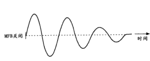
For example, Fig. 7 A to 7C shows the difference under the situation that difference in the retardance state of vibrating membrane of loudspeaker unit 16 is considered transient phenomenon.Fig. 7 A to 7C is schematic diagram, only is used for easy to understand for the difference of the transient phenomenon of every kind of operator scheme.
Fig. 7 A shows the characteristic of closing the pattern situation corresponding to the MFB-of Fig. 3, and Fig. 7 B shows the characteristic corresponding to the MFB-on-mode situation of Fig. 4, and Fig. 7 C shows the characteristic corresponding to the 2nd MFB-on-mode situation of Fig. 5.These figure can regard as, be right after constantly 0 stop to loudspeaker unit 16 provide drive signal after, near the measurement of the motion of vibrating membrane (low band resonance frequency f 0).
Close at MFB-under the situation of pattern, the damping that produces because of MFB is invalid.Therefore, as shown in Fig. 7 A, formed the characteristic of amplitude slow-decay after 0 past constantly.
On the other hand, in the MFB-on-mode shown in Fig. 7 B, apply decay based on the MFB of speed feedback-type.Therefore, amplitude is decayed comparing in the shorter time shown in Fig. 7 A from constantly 0 beginning.This representation case is as suppressed in order to be enhanced in the vibration mode of the sound of so-called " buzz ".
In addition, in the 2nd MFB-on-mode shown in Fig. 7 C, amplitude was decayed within the short time of 0 beginning constantly.Yet, compare the situation of Fig. 7 B, formed the wherein elongated a little image of time of amplitude fading of a width.As a kind of explanation, this expression " buzz " is subject to the inhibition same with situation shown in Fig. 7 B, and compares with the situation shown in Fig. 7 B and form one the residual listen mode of a little reverberation is arranged.
Although as mentioned above frequency characteristic be corrected as in a MFB-on-mode and the 2nd MFB-on-mode identical, still variant between the sense of hearing impression of the sound that reproduces in loudspeaker unit 16 and listen mode.
Difference between the listen mode of the one MFB-on-mode and the 2nd MFB-on-mode does not represent that a kind of pattern just definitely is better than another kind of pattern.Thus, this difference can think to show that pattern any according to audience's taste all caters to the need.In addition, for identical audience, can according to the type of sound source that will be reproduced, as style, change and think desirable pattern.
In this viewpoint, under the situation of MFB signal processing system by the digital circuit configuration, can consider for the application of switching between a MFB-on-mode and the 2nd MFB-on-mode that operates according to the user.
In other words, except the change of the open/close state of MFB, can carry out any selection according to the taste of the sound consistent with opening MFB and will switch to a MFB-on-mode or the operation of the 2nd MFB-on-mode.
According to the handover operation between the operator scheme of MFB, for example by the data of the mode setting table shown in digital signal processing unit 10 storage maps 8.
In mode setting table shown in Figure 8, at first, definition MFB-closes the operator scheme item in pattern, a MFB-on-mode and the 2nd MFB-on-mode.Can select any one operation as MFB in these operator schemes.Then, the content of ON/OFF setting of content, acceleration feedback-type MFB of the ON/OFF setting of speed feedback-type MFB and the equalizer correcting feature that will arrange in low-band correction equalizer 12 are associated with each operator scheme.
In Fig. 8, close pattern corresponding to MFB-, expression speed feedback-type MFB will be closed with acceleration feedback-type MFB and will be closed.In addition, about the equalizer correcting feature, low-band correction equalizer 12 is represented as and will be passed through.
On the other hand, corresponding to a MFB-on-mode, expression speed feedback-type MFB will be opened and acceleration feedback-type MFB will be closed.In addition, write in the drawings " characteristic 1 " as the equalizer correcting feature.Yet in fact, characteristic is reformed target frequency, and characteristic is designated as the parameter (as gain) at reformed target frequency place and for example is used for correcting feature (equalization characteristic) that frequency characteristic is flattened.
On the other hand, expression speed feedback-type MFB will be opened and will be opened with acceleration feedback-type MFB.About writing the equalizer correcting feature of " characteristic 2 ", specified the parameter that is used for making the correcting feature that the frequency characteristic corresponding to the 2nd MFB-on-mode flattens.
At this, suppose according to user's operation and selected MFB-to close pattern.Therefore, for example close with reference to mode setting table identification shown in Figure 8 and MFB-as the digital signal processing unit 10 of DSP pattern association speed feedback-type MFB open/close content, acceleration feedback-type MFB be set open/close content and equalizer correcting feature be set.Then, the signalization treatment system makes that speed feedback-type MFB is closed, acceleration feedback-type MFB is closed, low-band correction equalizer 12 will be passed through.As a result, consisted of the digital information processing system that MFB-closes pattern.
On the other hand, corresponding to the selection of a MFB-on-mode, digital signal processing unit 10 forms signal processing system according to arrange open/close content and the equalizer correcting feature that open/close content, acceleration feedback-type MFB are set of speed feedback-type MFB related with a MFB-on-mode in mode setting table.In other words, form a closed loop in digital signal processing unit 10, make that speed feedback-type MFB is opened, acceleration feedback-type MFB is closed, and in low-band correction equalizer 12, the parameter by " characteristic 1 " expression is set.
On the other hand, corresponding to the selection of the 2nd MFB-on-mode, digital signal processing unit 10 forms signal processing system according to arrange open/close content and the equalizer correcting feature that open/close content, acceleration feedback-type MFB are set of speed feedback-type MFB related with the 2nd MFB-on-mode in mode setting table.In other words, form a closed loop in digital signal processing unit 10, make speed feedback-type MFB and acceleration feedback-type MFB all be opened, and in low-band correction equalizer 12, the parameter by " characteristic 2 " expression is set.
3-4. application example (the second example)
In the application corresponding to the first example of mode setting table shown in Figure 8, be assumed to the yield value (feedback oscillator value) that a MFB-on-mode and the 2nd MFB-on-mode arrange and be fixed to unique in control portion of gain divides 21 and 24.
Yet the control portion of gain that comprises in the digital signal processing unit 10 as digital circuit divides the parameter of 21 and 24 yield value can change in an easy manner to arrange.For example, by the operator scheme that all is opened for speed feedback-type MFB and acceleration feedback-type MFB, control portion of gain is set and divides 21 and 24 each gain, can suitably change the feedback quantity of speed feedback-type MFB and the feedback quantity of acceleration feedback-type MFB and be used for arranging.Therefore, along with each feedback quantity of speed feedback-type MFB or acceleration feedback-type MFB is changed, the listen mode of the sound that reproduces in loudspeaker unit 16 changes according to the combination of the feedback quantity of speed feedback-type MFB and acceleration feedback-type MFB.In addition, for example, compare with the situation of the open/close combination of acceleration feedback-type MFB with the ON/OFF of operating speed feedback-type MFB, can the listen mode of sound be set more subtly according to the combination of the feedback quantity of speed feedback-type MFB and acceleration feedback-type MFB, this is identical with the application in the first example.
For example, even in the situation that use identical audio-source, suitable acoustic tones is for such as the sound of the video content of film be also different such as the sound of the audio content of CD.For example, for create atmosphere, reverberation is to a certain degree arranged in the sound of film etc.On the other hand, the sound due to audio content needs more Hi-Fi reproduction, the preferably reverberation of the acoustic phase same level of reservation and film.In addition, think that the acoustic tones of desired audio content is different, for example according to style of music etc.
Consider said circumstances, the second example of following configuration the application.
At first, pre-determine the combination of the feedback quantity of speed feedback-type MFB and acceleration feedback-type MFB, the yield value that namely arranges in control portion of gain divides 21 and 24, for its obtain be suitable for reproducing such as the acoustic tones of the content type of the audio-source of film or music or be suitable for the acoustic tones of the style of audio content.
Then, according to determined content, for example generate as shown in Figure 9 gain-correcting feature table, and in digital signal processing unit 10 storage gain-correcting feature table.
As shown in Figure 9, at first, each list item is classified as the content type of film and music basically.In addition, the content type of music is again according to the genre classification as rock and roll, jazz and allusion.In addition, film, rock and roll, jazz and classic each are associated with the gain of speed feedback-type MFB, gain and the equalizer correcting feature of acceleration feedback-type MFB.
As the gain of speed feedback-type MFB, be illustrated in control portion of gain and divide the yield value corresponding to speed feedback-type MFB that will arrange in 21.At this, the yield value corresponding to film, rock and roll, jazz and classic each that will arrange in control portion of gain divides 21 is represented by a1, b1, c1 and d1.
Similarly, as the gain of acceleration feedback-type MFB, be illustrated in control portion of gain and divide the yield value corresponding to acceleration feedback-type MFB that will arrange in 24.At this, the yield value corresponding to film, rock and roll, jazz and classic each that will arrange in control portion of gain divides 24 is represented by a2, b2, c2 and d2.
Therefore, when the combination of the feedback quantity of the feedback quantity of speed feedback-type MFB and acceleration feedback-type MFB, i.e. yield value (feedback oscillator value) when being changed, the frequency characteristic of the sound that reproduces from loudspeaker unit 16 that obtains based on this combination changes.Therefore, for by utilizing low-band correction equalizer 12 correcting frequency characteristics to make it smooth, for example as mentioned above, may need according to the frequency characteristic of obtaining based on the combination of yield value, the equalizer correcting feature to be set.The equalizer correcting feature of arranging in gain shown in Figure 9-correcting feature table has represented the equalization characteristic of basis corresponding to the low-band correction equalizer 12 of the frequency characteristic setting of each combination of every yield value.
The user is allowed to carry out the selection operation of content type and style.When corresponding to the content of table data shown in Figure 9, can select one as this operation from " film " and " rock and roll " of the content type of music, " jazz " and " allusion " four options.
Then, the content type of making according to user's operation and the selection of style, digital signal processing unit 10 obtains the gain of the speed feedback-type MFB related with selected content type or style, gain and the equalizer correcting feature of acceleration feedback-type MFB from gain-correcting feature table.Then, digital signal processing unit 10 changes that control portion of gain divide 21 and 24 yield value and the equalization characteristic of the low-band correction equalizer 12 that will arrange according to the content of obtaining.
As mentioned above, in the application of the second example, come Lookup protocol to be suitable for the effective status of the MFB of selected content type and style according to the user to the content type of the reproduced audio-source that will be used to specify and the selection of style.In other words, change the effective status of MFB, with the acoustic tones of the producing sound that obtains the content type that is suitable for the specified audio-source of user and style.
Content type shown in Figure 9 and style are only examples.In addition, in the application of the second example, described speed feedback-type MFB and acceleration feedback-type MFB all is opened, and the yield value (feedback quantity) of each content type and style is changed for setting in the description of the application of the second example.Yet, also be used in combination the open/close combination of speed feedback-type MFB and acceleration feedback-type MFB in the second example.For example, the setting that can use speed feedback-type MFB only to be opened, and the yield value under this situation is changed.
In addition, in the application of the first above-mentioned example, for example it is also conceivable that for example MFB-is closed the selection operation use of pattern, a MFB-on-mode and the 2nd MFB-on-mode according to the user interface of the second example.In other words, for example, for MFB-closes the expression formula that each option of pattern, a MFB-on-mode and the 2nd MFB-on-mode is given representative voice tone or style title, content type etc.
In addition, in description up to now, the equalizer correcting feature of supposing low-band correction equalizer 12 is that flat characteristic is as target frequency characteristic.Yet this is only an example.As long as can acoustically obtain a good result, can arrange such as low-frequency band and be thus lifted to specific rank or any characteristic of the characteristic that is cut, as the target frequency characteristic except flat characteristic.
In addition, may to need not be to the operator scheme of MFB or general to the combination of feedback quantity to target frequency characteristic.For example, in order to obtain more desirable acoustic tones, can be wittingly different frequency characteristics be set for the combination of the operator scheme of MFB or feedback quantity.
4. digital MFB: revise example
Up to now, described according to wherein basically using the bridge detection method and being used in combination speed feedback-type MFB and the configuration of the embodiment of acceleration feedback-type MFB.
According to this bridge detection method, detect back electromotive force by bridgt circuit 17.Therefore, recognized the advantage of bridge detection method: such as not needing to arrange physical sensors in the vibrating membrane of loudspeaker unit 16 grades, with and physical structure uncomplicated.
Yet, as the detection method that is used for MFB, known except the bridge detection method for example by utilizing the Static Electro container, the method for the displacement of the vibrating membrane of the detection loudspeaker units 16 such as laser displacement system.
Therefore, as the correction example of the MFB signal processing system of the present embodiment, figure 10 illustrates the profile instance that adds displacement detecting to configuration shown in Figure 2.In Figure 10, give identical Reference numeral to the part identical with the part of Fig. 2, and its description is omitted.
As shown in figure 10, at first, layout is for detection of the displacement transducer 29 of the displacement of the vibrating membrane of loudspeaker unit 16.Displacement transducer 29, for example by the Static Electro container, the configuration such as laser displacement system.The analog detection signal that obtains by the displacement of the vibrating membrane in detecting position displacement sensor 29 is exaggerated 25 amplifications of device circuit and is converted to digital signal by ADC26, in order to output to digital signal processing unit 10.
Digital signal processing unit 10 in this situation comprises that also LPF27 and control portion of gain divide 28.By allowing to pass through LPF27 from the digital displacement detection signal of ADC input, eliminated unnecessary high band component, and divided 28 to apply gain by control portion of gain.Then to synthesizer 13 output result signals as feedback signal.
Under this configuration, in the application of the first example, speed feedback-type MFB, acceleration feedback-type MFB, be changed with the open/close combination of the MFB that carries out based on the detection of displacement, and the correcting feature of low-band correction equalizer 12 also is changed to according to this combination and arranges.
In addition, application corresponding to the second example, determine that according to predefined content type and style control portion of gain divides the combination of 21,24 and 28 yield value, and the equalizer correcting feature of determining based on yield value with according to each combination be combined to form gain-correcting feature table.
As mentioned above, with regard to the present embodiment, the number of the MFB detection method that is used in combination and the integrated mode of detection method are not specially limited.
In addition, even when using identical detection method and identical feedback method, also can suitably change for detection of configuration, be used for configuration that signal processes etc.For instance, with regard to the speed corresponding to speed feedback-type MFB detects, for example, also become known for arranging the technology of magnetic test coil in loudspeaker unit 16.In addition, by sense acceleration with calculate the signal that the integration of signal can acquisition speed detects.In addition, for acceleration detection, can use acceleration transducer, the acoustic pressure that perhaps can use by using microphone detects.
5. the adjustment of feedback oscillator
5-1. the adjustment in analog circuit
The yield value of the feedback oscillator of MFB signal processing system is set, for example makes the feedback quantity that can obtain expectation.Yet although identical yield value is set, the actual feedback quantity that obtains is because of the variation of the characteristic of loudspeaker unit, such as for detection of variation of the simulated assembly of the motion of vibrating membrane etc. and different.Therefore, in order to absorb above-mentioned variation and in fact to obtain suitable feedback quantity, preference is adjusted feedback oscillator as transport product at least one stage before the user from factory.
Therefore, at first, figure 19 illustrates the profile instance that uses analog circuit, can adjust the MFB signal processing system of feedback oscillator.Configuration shown in Figure 19 has configuration shown in Figure 15 as its basis.Therefore, give identical Reference numeral for each part identical with part shown in Figure 15, and the descriptions thereof are omitted.
As shown in figure 19, insert switch SW 1 between the input of the output of amount of gain adjustment unit 108 and synthesizer 102.In addition, insert switch SW 2 between the input of the output of low-band correction equalizer 101 and synthesizer 102.Switch SW 1 is the conduction and cut-off switch, and switch SW 2 is the change over switches that change the connection that terminal tm1 is connected with tm3 to terminal tm2.The terminal tm1 of switch SW 2 is connected to the input of synthesizer 102, and the terminal tm2 of switch SW 2 is connected to the output of low-band correction equalizer 101.In addition, terminal tm3 opens corresponding to normal running.
In normal running, as shown in figure 19, switch SW 1 is opened, and terminal tm1 is connected to the terminal tm2 in switch SW 2.Therefore, as the MFB signal processing system, form closed loop circuit shown in Figure 1, and the audio signal of input is output to synthesizer 102 by low-band correction equalizer 12.In other words, formed the circuit of the normal signal processing that can carry out MFB.
On the other hand, in order to adjust feedback oscillator, as shown in figure 20, switch SW 1 is closed.Therefore, the output of amount of gain adjustment unit 108 is not input to synthesizer 102, thereby forms an open loop.Switch SW 2 is shifted with splicing ear tm1 to terminal tm3, and the measuring-signal that is used for the feedback oscillator adjustment is imported into terminal tm3.Therefore, measuring-signal but not the audio signal of audio-source is imported into the MFB signal processing system of open loop.
In addition, the measuring-signal as corresponding to the MFB signal processing system that is configured by analog circuit for example, can use corresponding to frequency band to be measured the sine sweep signal of white noise etc.
In addition, the output of amount of gain adjustment unit 108 is imported into the measurement monitoring arrangement, for example as supervisory signal.
In configuration shown in Figure 20, the measuring-signal that is input to the terminal tm3 of switch SW 2 passes through power amplifier 103, loudspeaker unit 104, bridgt circuit 105, detector/amplifier circuit 106, low pass filter 107 and amount of gain adjustment unit 108 are acquired as supervisory signal.
Suppose that the frequency characteristic of supervisory signal is as shown in figure 21 as the result of measuring.Therefore, supervisory signal has characteristic: obtain peak value at low band resonant frequency f0=80Hz place.For instance, here, MFB signal processing system hypothesis applies the feedback of 12dB at the closed loop state.When being represented by α, open-loop gain is α-1 when the feedback quantity (magnification ratio) of closed loop.
Therefore, in the case, for example, the adjusting operation personnel manually adjust the variable resistor device as amount of gain adjustment unit 108, observe simultaneously supervisory signal, making peak power at low band resonant frequency f0=80Hz place is 3 times of power (level) of measuring-signal.
As mentioned above, for the situation of the MFB signal processing system that is configured by analog circuit, feedback oscillator may need by manual adjustment.Therefore, be difficult to carry out the accurate adjustment of feedback oscillator for each equipment with MFB signal processing system.
In addition, for the situation of analog circuit, for example, after the stage before transporting adjusted feedback oscillator, switch SW 1 and SW2 were displaced to state shown in Figure 19 from state shown in Figure 20, and for example, this device is assembled etc., then is transported.Therefore, usually be passed at this device and be difficult to adjust feedback oscillator in stage of domestic consumer.In other words, generally speaking, the adjustment of feedback oscillator is confined to the fabrication stage.Even when this equipment is configured such that the variable resistor device of switch SW 1 and SW2 and amount of gain adjustment unit can be operated simply by domestic consumer, also may needs measuring equipment etc. to be used for adjusting, and may need corresponding technology.In other words, preferably do not allow domestic consumer can adjust this device.
5-2. the adjustment in digital circuit
Therefore, with regard to the present embodiment, the following configuration that can automatically adjust feedback oscillator is proposed.
Figure 11 shows the profile instance of the MFB signal processing system that is used for the adjustment feedback oscillator that is configured by digital circuit as an embodiment.In the figure, give identical Reference numeral for an every part identical with the part shown in Fig. 1 and 2, and the descriptions thereof are omitted.With regard to the present embodiment, as shown in Fig. 2 waits, include a plurality of configurations with feedback control system of different feedback methods in the Digital Signal Processing stage and be used as its basic configuration.Yet in order easily to understand specification, Figure 11 shows the profile instance based on the configuration of the feedback control system that only includes a speed feedback-type shown in Figure 1.
Under the MFB signal processing system by the present embodiment of digital circuit configuration, when adjusting feedback oscillator, form as shown in figure 11 digital signal processing unit 10, for example, DSP, signal processing operations.In other words, digital signal processing unit 10 is configured to comprise measuring-signal generating portion 31, playback buffer device 32, and LPF20, buffer 33, FFT part 34, contrary-TSP processing/feature extraction part 35, and gain arranges part 36.
Measuring-signal generating portion 31 in this situation is digital circuits and thus, for example, generates TSP (temporal extension pulse) signal as measuring-signal.In other words, impulse response is measured and to be used to the measurement carried out for adjusting feedback oscillator here.The TSP signal that is generated by measuring-signal generating portion 31 is stored in playback buffer device 32.The data of at first, reading from playback buffer device 32 are set up as digital TSP signal and by output from digital signal processing unit 10.This TSP signal is converted to analog signal by DAC14 and is amplified by power amplifier 15, in order to be provided for the voice coil of loudspeaker unit 16.Be bridged circuit 17 according to the motion of the vibrating membrane of the loudspeaker unit 16 of this moment TSP signal and detect and be output to ADC19 as the amplification detection signal that comes self-detector/amplifier circuit 18.ADC19 is converted to the analog detection signal of input digital detection signal and exports this digital detection signal.
In digital signal processing unit 10, by passing through LPF20 from the digital detection signal of ADC19 output, eliminated unnecessary high band component.Buffer 33 loads the TSP response signal of passing through many pre-determined numbers of LPF20, and for example, calculating mean value, and this mean value is sent to FFT part 34.
In FFT part 34, carry out for the TSP response signal after average the frequency analysis of for example using FFT (fast fourier transform) and process.In addition, contrary-TSP processing/feature extraction part 35 is to carry out contrary-TSP from the data that TTF part 34 transmits to process.Therefore, in this case, with regard to the MFB signal processing system of open loop, obtained the characteristic of the measuring-signal that the system of Negotiation speed feedback-type transmits.
Therefore, gain arranges part 36 and based on the difference that appears at by between the value of the value of the peak level (low band resonant frequency f0) in the frequency characteristic of contrary-TSP processings/feature extraction part 35 measurements and target peak level, feedback oscillator is set.For example, at the represented peak level of frequency characteristic by contrary-TSP processing/feature extraction part 35 measurements be-5dB, the target peak level is under the situation of 9dB, and feedback oscillator is 9-(5)=14dB.
MFB signal processing system shown in Figure 11 is open loop.Be difficult to carry out the measurement be used to feedback oscillator is set, unless the MFB signal processing system is open loop.Therefore, until the feedback oscillator that this one-phase obtains has the value corresponding to open loop.In the situation that in fact MFB applies by the MFB signal processing system, form closed loop shown in Figure 1.Yet, have the feedback oscillator of target peak level, that is this moment, the feedback oscillator during closed loop, the feedback oscillator during with respect to open loop has error.
Feedback oscillator value when the feedback oscillator value when therefore, gain arranges part 36 based on above-mentioned open loop of obtaining is obtained closed loop.The object lesson of calculation expression has omitted.Yet the calculating of the feedback oscillator value that the feedback oscillator value when closed loop can be when utilizing above-mentioned open loop of obtaining comes unique obtaining.
The feedback oscillator value that digital signal processing unit 10 storage is above-mentioned when by gain, the closed loop that part 36 obtains being set is as the parameter that arranges in control portion of gain divides 21.Then, when in fact allowing the MFB signal processing system, for example, under the situation corresponding to Figure 11, digital signal processing unit 10 forms signal processing system shown in Figure 1.At that time, the feedback oscillator value of storage arranges in control portion of gain divides 21.
As mentioned above, in the feedback oscillator of the present embodiment is adjusted, the automatic acquisition optimal value.In addition, when the measurement of carrying out for open loop, the yield value in the time of can finally obtaining corresponding to closed loop.
In addition, above-mentioned can self-adjusting feedback oscillator can redescribe into, even be configured to also can not occur as the worry in the situation of analog circuit such as according to user's capable of regulatings such as operation the time in the feedback oscillator value.
Therefore, the equipment with MFB signal processing system of the present embodiment is configured such that, can carry out according to user's operation the operation of the adjustment that is used for instructing the feedback oscillator value.Then, according to the operation for the adjustment of instructing the feedback oscillator value, at first digital signal processing unit 10 forms the signal processing system of open loop shown in Figure 11, begin to measure, and the feedback oscillator value when finally obtaining closed loop, and store the feedback oscillator value of obtaining.Then, when after when moving the MFB signal processing system, the feedback oscillator value of up-to-date storage is set up in control portion of gain divides.
For example, along with change of time etc., the reproducing characteristic of loudspeaker unit 16 or the characteristic of simulated assembly may change.When the change of this specific character occurs, for example the yield value that arranges up to now with along with in fact this change error occurs between the yield value of optimum.When feedback oscillator value as mentioned above can be according to the operating in random time and readjusted of user, usually can be set to optimum and operate MFB by change the feedback oscillator value along with the above-mentioned time.
In addition, in fact, as shown in Fig. 2 and 10, made up under the situation of configuration of MFB signal processing system of a plurality of feedback control systems the feedback oscillator value in the time of can obtaining the closed loop of each system in application.
For instance, under the situation corresponding to the configuration of Fig. 2, form the MFB signal processing system by open loop from the acceleration feedback-type to configuration shown in Figure 11 that further add.In other words, at first, arrange difference processing part 22 and LPF23 shown in Figure 2 in digital signal processing unit 10.Even in this case, the digital detection signal from ADC19 output can be branched and be input to difference processing part 22.In addition, in the rear one-level of LPF23, by buffer 33, FFT part 34, contrary-TSP processing/feature extraction part 35 and gain arrange that part 36 forms corresponding to the parallel setting of system with speed feedback-type shown in Figure 11 of the system of acceleration feedback-type.Therefore, during control portion of gain divides 24 corresponding to the yield value of acceleration feedback-type setting with to obtain together with the yield value of speed feedback-type setting during control portion of gain divides 21.
In addition, under the situation of yield value according to the configuration of each change of content type or style, use similar MFB corresponding to table data shown in Figure 9 to control, obtain the feedback oscillator value according to each.In the case, for the signal processing system of the like combinations with the feedback method that will be opened, by the measured feedback oscillator value of obtaining corresponding to a signal processing system, this becomes the basis in them.Next, consider following method: for example, be the side-play amount of other signal processing systems settings with respect to basic feedback oscillator value, deviation ratio etc., and obtain each feedback oscillator value by calculating.
6. the adjustment of the correcting feature of equalizer
6-1. the adjustment in analog circuit
Under the above-mentioned situation that can adjust the feedback oscillator value, even when the feedback oscillator value is changed, need not changes equalization characteristic and also can change the frequency characteristic of the producing sound of loudspeaker unit 16.Therefore, the correcting feature of low-band correction equalizer 12 (equalization characteristic) also needs again to arrange according to the feedback oscillator value after adjusting.
Therefore, for example, for the MFB signal processing system by the analog circuit configuration shown in Figure 1, equalization characteristic can followingly arrange.
At first, arrange the microphone for the sound that is received in loudspeaker unit 16 reproductions, and be set to MFB signal processing system shown in Figure 1 according to close loop maneuver under the state of flat characteristic in the characteristic of low-band correction equalizer 101.In other words, MFB is opened.Then, under the state that MFB is opened, measure the frequency band of the audio signal of obtaining by the sound that receives from microphone.The operator for example, manually changes the equalization characteristic of low-band correction equalizer 101, monitors simultaneously measured frequency characteristic, and making measured frequency characteristic is target frequency characteristic.
As mentioned above, under the state that MFB is opened, in the MFB signal processing system by the analog circuit configuration, the adjustment of equalization characteristic may need manual execution, needs thus measurement mechanism.Therefore, under the situation of considering common situation, execution previous stage that is adjusted at the fabrication stage or transports from factory of equalization characteristic, and be not suitable for allowing the user to adjust equalization characteristic.
6-2. the adjustment in digital circuit
Figure 12 shows the profile instance of the adjustment of the equalization characteristic (equalizer correcting feature) corresponding to the present embodiment.Even in this case, for convenience of describing, show use only by the configuration under the prerequisite of the MFB signal processing system of the system configuration of a speed feedback-type.In Figure 12, give identical Reference numeral for an every part identical with part shown in Figure 11, and the descriptions thereof are omitted.Configuration shown in Figure 12 is that the equalizer correcting feature arranges part 37 and Parameter storage part 38 forms by adding to configuration shown in Figure 11.Feedback oscillator value β during closed loop that Parameter storage part 38 storage in this situation will arrange in control portion of gain divides 21 and with the equalizer correcting feature γ of setting in low-band correction equalizer 12 therein, as parameter.
The equalizer correcting feature arranges part 37 based on the feedback oscillator value β new that part 36 newly obtains being set by gain and being stored in feedback oscillator value β and equalizer correcting feature γ in Parameter storage part 38, obtains the new equalizer correcting feature γ new corresponding to the feedback oscillator value β new that newly obtains.
Figure 13 represents to arrange the process of the equalizer correcting feature of being carried out by digital signal processing unit shown in Figure 12 10, as flow chart.In addition, the step that represents in this figure for example, can be considered to by gain, part 36 or equalizer correcting feature to be set and arrange that part 37 suitably carries out.
At first, gain arranges the feedback oscillator value α of part 36 when step S101 measures corresponding to open loop, and at step S102 the new feedback oscillator value β new when calculating in new closed loop with the calculating of feedback oscillator value α.The process of step S101 and S102 can be carried out by the order of describing above with reference to Figure 11.
Next, at step S103, the equalizer correcting feature arranges part 37 and reads feedback oscillator value β and the equalizer correcting feature γ that is stored in Parameter storage part 38.
Then, at step S104, the equalizer correcting feature arranges part 37 based on using the feedback oscillator value β that reads at step S103 and equalizer correcting feature γ and in the calculating of the precalculated new feedback oscillator value β new of step S102, calculating new equalizer correcting feature γ new.
The description of the object lesson of the calculation expression of computation balance device correcting feature γ new is omitted.Yet, as a kind of computational algorithm, for example, at first, obtain new feedback oscillator value β new and the feedback oscillator value β that uses up to now between difference.Then, obtain the error of for example supposing the frequency characteristic that generates according to the difference of obtaining.When getting this error, unique correcting value that obtains for the balancer characteristic of this error of compensation.Then, calculate to change the equalizer correcting feature γ that uses up to now according to correcting value by execution, obtain new equalizer correcting feature γ new.
Then, the equalizer correcting feature arrange part 37 arrange the above-mentioned equalizer correcting feature γ new that newly obtains as after to be stored in equalizer correcting feature γ in Parameter storage part 38 at step S105.Similarly, the equalizer correcting feature arranges part 37 and is arranged on the feedback oscillator value β new corresponding to above-mentioned equalizer correcting feature γ new that step S102 has obtained, as the feedback oscillator value β that will be stored in afterwards in Parameter storage part 38.
Therefore, in the present embodiment, the feedback oscillator value arranges recently, and the equalizer correcting feature corresponding to the feedback oscillator value that recently arranges can be set in addition.In other words, except the feedback oscillator value, can automatically adjust the equalizer correcting feature.
With Fig. 2 and 10 be similarly, made up in application under the situation of configuration of MFB signal processing system of a plurality of feedback control systems 1 to n, at first, as mentioned above, the feedback oscillator value β new (1) during for each system acquisition closed loop is to β new (n).In addition, part 37 is set is that each new feedback oscillator value β new (1) that obtains of a plurality of systems carry out to calculate to the feedback oscillator value β (1) of β new (n) and storage in Parameter storage part 38 to β (n) by use to the equalizer correcting feature.As the result of calculating, obtain the error of frequency characteristic and the correcting value of balancer characteristic, and finally obtain equalizer correcting feature γ new.
In addition, about how the equalizer correcting feature be set to transport from factory previous stage initial storage characteristic, for example, in order to accurately arrange according to the variation of each device, can carry out following process.
Figure 14 shows the profile instance corresponding to the MFB signal processing system of the adjustment of initial equalizer correcting feature.In the figure, for example form MFB signal processing system according to closed loop same as shown in Figure 2.In addition, in the outside of digital signal processing unit 10, add microphone 41, amplifier of microphone 42 and ADC43.In addition, digital signal processing unit 10 comprises buffer 44 in addition, FFT part 45, and contrary-TSP processing/feature extraction part 46 and equalizer correcting feature arrange part 47.
Then, for the equalizer correcting feature is set, at first measuring-signal is input to ADC11, and operation MFB signal processing system.At this moment, the correcting feature of low-band correction equalizer 12 is set to flat characteristic.In other words, this configuration is identical with the configuration by low-band correction equalizer 12.In addition, adjust in advance control portion of gain and divide 21 feedback oscillator value.
Cloth microphone 41 is to receive the sound that reproduces from loudspeaker unit 16.Therefore, can obtain by microphone 41 audio signal that meets the sound that obtains by use loudspeaker unit 16 reproduction measuring-signals.This audio signal is exaggerated by for example amplifier of microphone 42, and is converted into digital signal by ADC 43, in order to be input to digital signal processing unit 10.
At digital signal processing unit 10, by the received digital audio and video signals of its sound is passed through buffer 44, FFT processing section 45 and contrary-TSP processing/feature extraction part 46, execution is equal to buffer shown in Figure 12 33, the processing of FFT processing section 34 and contrary-TSP processing/feature extraction part 35 execution.In other words, can obtain the frequency characteristic of the measurement sound that is received by microphone.
The equalizer correcting feature arranges part 47 and obtains one to be used for contrary-correction of frequency characteristic that TSP processing/feature extraction part 35 is obtained be the correcting value of target frequency characteristic.In other words, the equalizer correcting feature arranges part 47 and obtains equalizer correcting feature γ.Then, the equalizer correcting feature γ that obtains as mentioned above for example is stored in Parameter storage part 38 shown in Figure 12.
The present embodiment is not limited to the configuration of describing up to now.
For example, in the configuration of above-mentioned MFB signal processing system, digital signal is converted into analog signal by DAC14 and is disposed in power amplifier 15 amplifications of inert stage in order to drive loudspeaker unit 16.Yet this part can be by the configuration of D class A amplifier A, and this amplifier receives digital audio and video signals as inputting and drive loudspeaker unit etc.
In addition, as mentioned above, be the feedback method of MFB combination, the type of the transducer of the motion of detection loudspeaker vibrating diaphragm, circuit etc., number of the feedback method that make up etc. is not limited to above-mentioned configuration, but can appropriate change.
The application comprises and the theme of on June 12nd, 2009 at the disclosed Topic relative of the Japanese priority patent application JP2009-140968 of Japan Office application, and its full content is incorporated herein by reference at this.
Those skilled in the art should be understood that, various corrections, and combination, sub-portfolio and variation may occur because of design requirement and other factors, as long as they are within the scope of appended claims and equivalent thereof.
Claims (10)
1. signal handling equipment comprises:
One or more checkout gears arrange to be used for according to detecting the motion of the vibrating membrane of loud speaker as first of different feedback methods to the n feedback method;
Analog-digital commutator, the one or more detection signals that are used for analog form that checkout gear is obtained are converted to digital form;
Feedback signal generating means is used for generating corresponding to the first feedback signal to the n feedback method by the detection signal that utilizes the digital form that analog-digital commutator obtains;
The correcting balancer device is used for arranging equalization characteristic, and the frequency characteristic with the audio source signal by changing digital form makes the sound by loudspeaker reproduction have target frequency characteristic;
Synthesizer is used for that self-correcting in the future is equalizing device, the audio source signal of the digital form of driving signal that will be output as loud speaker makes up with feedback signal;
The feedback operation setting device is used for from first to the n feedback method, the feedback method of carrying out the feedback operation that audio source signal and feedback signal are made up of being carried out by synthesizer being set, and does not carry out the feedback method of feedback operation; And
Equalization characteristic changes and setting device, and being used for will be by the equalization characteristic of correcting balancer device setting according to being changed by the feedback method of the set execution feedback operation of feedback operation setting device and the combination of not carrying out the feedback method of feedback operation.
2. according to claim 1 signal handling equipment also comprises:
The measuring-signal generating apparatus is used for the measuring-signal of generating digital form with the driving signal output as loud speaker; The frequency characteristic deriving means, be used for obtaining frequency characteristic by the detection signal that receives each feedback method, described detection signal is detected and is obtained by checkout gear when measuring-signal is provided for loud speaker as the driving signal, and is converted to digital form by analog-digital commutator; And
Gain regulator is used for the frequency characteristic based on the detection signal of each feedback method that is obtained by the frequency characteristic deriving means, obtains the gain that will be arranged by gain control for each feedback method,
Wherein feedback signal generating means comprises gain control, is used to that the feedback signal to each feedback signal of n feedback method to correspondence applies described gain corresponding to first.
3. according to claim 2 signal handling equipment also comprises:
The equalization characteristic deriving means, be used at least the gain based on each the new feedback method that is obtained by gain regulator, and until be the gain of each feedback method setting when having obtained gain for each new feedback method, for each the new feedback method corresponding to the time that new gain is set by gain control obtains equalization characteristic.
4. according to claim 2 signal handling equipment, gain when wherein at first gain regulator obtains feedback signal and be not synthesized the open loop of device combination based on the frequency characteristic of the detection signal that is obtained by the frequency characteristic deriving means, and the gain when obtaining feedback signal and be synthesized the closed loop of device combination by the calculating of the gain when utilizing open loop, as the gain of each feedback method that is arranged by gain control.
5. according to claim 3 signal handling equipment, gain when wherein at first gain regulator obtains feedback signal and be not synthesized the open loop of device combination based on the frequency characteristic of the detection signal that is obtained by the frequency characteristic deriving means, and the gain when obtaining feedback signal and be synthesized the closed loop of device combination by the calculating of the gain when utilizing open loop, as the gain of each feedback method that is arranged by gain control.
6. according to claim 2 signal handling equipment also comprises:
Gain changes and setting device, is used for changing and the gain that imposes on each feedback signal being set by gain control,
Wherein equalization characteristic change and setting device are according to change and the setting of the gain that the feedback signal corresponding with the feedback method of carrying out feedback operation applied, and change will be by the equalization characteristic of correcting balancer device setting.
7. according to claim 3 signal handling equipment also comprises:
Gain changes and setting device, is used for changing and the gain that imposes on each feedback signal being set by gain control,
Wherein equalization characteristic change and setting device are according to change and the setting of the gain that the feedback signal corresponding with the feedback method of carrying out feedback operation applied, and change will be by the equalization characteristic of correcting balancer device setting.
8. according to claim 4 signal handling equipment also comprises:
Gain changes and setting device, is used for changing and the gain that imposes on each feedback signal being set by gain control,
Wherein equalization characteristic change and setting device are according to change and the setting of the gain that the feedback signal corresponding with the feedback method of carrying out feedback operation applied, and change will be by the equalization characteristic of correcting balancer device setting.
9. according to claim 5 signal handling equipment also comprises:
Gain changes and setting device, is used for changing and the gain that imposes on each feedback signal being set by gain control,
Wherein equalization characteristic change and setting device are according to change and the setting of the gain that the feedback signal corresponding with the feedback method of carrying out feedback operation applied, and change will be by the equalization characteristic of correcting balancer device setting.
10. signal processing method comprises the following steps:
The the first one or more detection signals that detect the analog form that one or more detecting units of motion of the vibrating membrane of loud speaker obtain to the n feedback method that arrange to be used for according to as different feedback methods are converted to digital form;
Generate corresponding to the first feedback signal to the n feedback method by the detection signal that utilizes the digital form of obtaining in one or more detection signals are converted to the step of digital form;
By proofreading and correct balanced unit, equalization characteristic is set, the frequency characteristic with the audio source signal by changing digital form makes the sound by loudspeaker reproduction have target frequency characteristic;
In the future self-correcting is balanced unit, the audio source signal of the digital form of driving signal that will be output as loud speaker makes up with feedback signal;
The feedback method of carrying out the feedback operation that audio source signal and feedback signal are made up of carrying out in the step with audio signal and feedback signal combination is set to the n feedback method from first, and does not carry out the feedback method of feedback operation; And
Change the equalization characteristic that will arrange according to the feedback method of execution feedback operation set in the step of feedback method is set and the combination of not carrying out the feedback method of feedback operation in the step of equalization characteristic is set.
Applications Claiming Priority (2)
| Application Number | Priority Date | Filing Date | Title |
|---|---|---|---|
| JP2009140968A JP5321263B2 (en) | 2009-06-12 | 2009-06-12 | Signal processing apparatus and signal processing method |
| JP2009-140968 | 2009-06-12 |
Publications (2)
| Publication Number | Publication Date |
|---|---|
| CN101924972A CN101924972A (en) | 2010-12-22 |
| CN101924972B true CN101924972B (en) | 2013-11-06 |
Family
ID=43306475
Family Applications (1)
| Application Number | Title | Priority Date | Filing Date |
|---|---|---|---|
| CN2010101982061A Expired - Fee Related CN101924972B (en) | 2009-06-12 | 2010-06-04 | Signal processing apparatus and signal processing method |
Country Status (3)
| Country | Link |
|---|---|
| US (1) | US8761408B2 (en) |
| JP (1) | JP5321263B2 (en) |
| CN (1) | CN101924972B (en) |
Families Citing this family (30)
| Publication number | Priority date | Publication date | Assignee | Title |
|---|---|---|---|---|
| JP2009044268A (en) * | 2007-08-06 | 2009-02-26 | Sharp Corp | Sound signal processing device, sound signal processing method, sound signal processing program, and recording medium |
| EP2490458B1 (en) * | 2011-02-15 | 2016-09-21 | Nxp B.V. | Control of a loudspeaker unit |
| JP2012186676A (en) * | 2011-03-07 | 2012-09-27 | Sony Corp | Signal processing device and signal processing method |
| US8965756B2 (en) * | 2011-03-14 | 2015-02-24 | Adobe Systems Incorporated | Automatic equalization of coloration in speech recordings |
| US10117036B2 (en) | 2011-07-15 | 2018-10-30 | Mediatek Inc. | Calibration method and calibration module thereof for vibration device |
| US9124961B2 (en) * | 2011-07-15 | 2015-09-01 | Mediatek Inc. | Control device for driving multi-function speaker by using digital mixing scheme and related control method thereof |
| CN102595280B (en) * | 2012-01-18 | 2014-12-10 | 精拓丽音科技(北京)有限公司 | Speaker integrated system with sensor feedback and drive circuit |
| JP5205526B1 (en) * | 2012-02-29 | 2013-06-05 | 株式会社東芝 | Measuring apparatus and measuring method |
| KR101355136B1 (en) * | 2012-08-14 | 2014-01-29 | 주식회사 이엠텍 | Sound transducer with function of processing electric signal independently |
| KR101409247B1 (en) * | 2012-08-20 | 2014-06-24 | 주식회사 이엠텍 | Sound transducer with selection between speaker and receiver functions |
| US9094751B2 (en) * | 2012-11-19 | 2015-07-28 | Microchip Technology Germany Gmbh | Headphone apparatus and audio driving apparatus thereof |
| CN104079247B (en) * | 2013-03-26 | 2018-02-09 | 杜比实验室特许公司 | Balanced device controller and control method and audio reproducing system |
| WO2015012815A1 (en) * | 2013-07-23 | 2015-01-29 | Advanced Bionics Ag | Systems and methods for detecting degradation of a microphone included in an auditory prosthesis system |
| FI20136088L (en) | 2013-11-06 | 2015-05-07 | Genelec Oy | Method and device for storing equalization settings in active speakers |
| WO2015125195A1 (en) * | 2014-02-18 | 2015-08-27 | パナソニックIpマネジメント株式会社 | Audio signal amplification apparatus |
| TWI559781B (en) * | 2014-08-21 | 2016-11-21 | 國立交通大學 | Piezoelectric speaker driving system and method thereof |
| CN105872747A (en) * | 2015-12-01 | 2016-08-17 | 乐视致新电子科技(天津)有限公司 | Sound field calibration method, wireless remote control device and sound media playing device |
| TWI651971B (en) * | 2016-04-26 | 2019-02-21 | 宏達國際電子股份有限公司 | Hand-held electronic apparatus, sound producing system and control method of sound producing thereof |
| US9992571B2 (en) * | 2016-05-09 | 2018-06-05 | Cirrus Logic, Inc. | Speaker protection from overexcursion |
| CN110999316B (en) * | 2017-07-19 | 2021-07-27 | 高桥公太 | Signal generation device for generating force change signal for driving loudspeaker and loudspeaker |
| CN109327765B (en) * | 2017-07-31 | 2021-02-05 | 华为技术有限公司 | Audio signal processing method and device and terminal |
| CN107749306B (en) * | 2017-10-31 | 2020-01-21 | 维沃移动通信有限公司 | Vibration optimization method and mobile terminal |
| JP6995352B2 (en) | 2017-12-26 | 2022-01-14 | 株式会社Tok | Rod fixing device and telescopic rod unit using it |
| US10638226B2 (en) * | 2018-09-19 | 2020-04-28 | Blackberry Limited | System and method for detecting and indicating that an audio system is ineffectively tuned |
| US11955935B2 (en) | 2019-08-27 | 2024-04-09 | Panasonic Intellectual Property Management Co., Ltd. | Signal processing device and adjusting method |
| CN114095841A (en) * | 2020-08-25 | 2022-02-25 | 上海艾为电子技术股份有限公司 | Driving device and driving method of loudspeaker and electronic equipment |
| CN114095842A (en) * | 2020-08-25 | 2022-02-25 | 上海艾为电子技术股份有限公司 | Driving device and driving method of loudspeaker and electronic equipment |
| CN112261229B (en) * | 2020-09-11 | 2022-01-18 | 歌尔科技有限公司 | Bone conduction call equipment testing method, device and system |
| CN112769410A (en) * | 2020-12-25 | 2021-05-07 | 西安讯飞超脑信息科技有限公司 | Filter construction method, audio processing method, electronic equipment and storage device |
| WO2023135854A1 (en) * | 2022-01-12 | 2023-07-20 | パナソニックIpマネジメント株式会社 | Sound reproduction apparatus |
Family Cites Families (25)
| Publication number | Priority date | Publication date | Assignee | Title |
|---|---|---|---|---|
| US4180706A (en) * | 1976-04-30 | 1979-12-25 | Bang & Olufsen A/S | Loudspeaker motional feedback system |
| JPH0728473B2 (en) * | 1988-05-06 | 1995-03-29 | ヤマハ株式会社 | Impedance compensation circuit |
| US5014320A (en) * | 1988-05-25 | 1991-05-07 | Yamaha Corporation | Driving apparatus, and control information storage body and protection circuit therefor |
| JPH0737369Y2 (en) * | 1988-10-17 | 1995-08-23 | ヤマハ株式会社 | Drive device temperature compensation circuit |
| US5729611A (en) * | 1996-02-02 | 1998-03-17 | Bonneville; Marc Etienne | Loudspeader overload protection |
| JPH09289699A (en) | 1996-04-24 | 1997-11-04 | Sony Corp | Speaker device |
| JPH10271595A (en) * | 1997-03-21 | 1998-10-09 | Nec Corp | Speaker equipment utilizing feedback |
| JP2003037887A (en) * | 2001-07-25 | 2003-02-07 | Mitsubishi Electric Corp | Acoustic controller and acoustic system |
| CA2408045A1 (en) * | 2001-10-16 | 2003-04-16 | Audio Products International Corp. | Loudspeaker with large displacement motional feedback |
| JP2003264888A (en) * | 2002-03-07 | 2003-09-19 | Pioneer Electronic Corp | Speaker controller and speaker system |
| US20030194097A1 (en) * | 2002-04-16 | 2003-10-16 | Chih-Shun Ding | Motional feedback for a speaker system |
| JP2004159244A (en) * | 2002-11-08 | 2004-06-03 | Matsushita Electric Ind Co Ltd | Player |
| JP4185770B2 (en) * | 2002-12-26 | 2008-11-26 | パイオニア株式会社 | Acoustic device, acoustic characteristic changing method, and acoustic correction program |
| JP2005027069A (en) * | 2003-07-03 | 2005-01-27 | Pioneer Electronic Corp | Speaker device |
| JP2005039325A (en) * | 2003-07-15 | 2005-02-10 | Pioneer Electronic Corp | Loudspeaker system and adjustment method therefor |
| US20060104451A1 (en) * | 2003-08-07 | 2006-05-18 | Tymphany Corporation | Audio reproduction system |
| US20050069153A1 (en) * | 2003-09-26 | 2005-03-31 | Hall David S. | Adjustable speaker systems and methods |
| JP2005323204A (en) * | 2004-05-10 | 2005-11-17 | Atsuhito Hanamoto | Motional feedback device |
| JP2006197206A (en) * | 2005-01-13 | 2006-07-27 | Matsushita Electric Ind Co Ltd | Speaker device |
| JP4683279B2 (en) * | 2005-07-04 | 2011-05-18 | ソニー株式会社 | Drive device |
| JP4519041B2 (en) * | 2005-09-20 | 2010-08-04 | ローランド株式会社 | Speaker device for musical instrument |
| JP4210859B2 (en) | 2005-10-31 | 2009-01-21 | ソニー株式会社 | Method for measuring frequency characteristics and impulse response rise time, and sound field correction apparatus |
| JP4743080B2 (en) * | 2006-10-30 | 2011-08-10 | ティアック株式会社 | Motional feedback speaker system |
| JP4882773B2 (en) | 2007-02-05 | 2012-02-22 | ソニー株式会社 | Signal processing apparatus and signal processing method |
| EP2081403B1 (en) * | 2008-01-17 | 2014-08-13 | VLSI Solution Oy | Method and device for detecting a displacement and movement of a sound producing unit of a woofer |
-
2009
- 2009-06-12 JP JP2009140968A patent/JP5321263B2/en not_active Expired - Fee Related
-
2010
- 2010-05-20 US US12/783,906 patent/US8761408B2/en not_active Expired - Fee Related
- 2010-06-04 CN CN2010101982061A patent/CN101924972B/en not_active Expired - Fee Related
Also Published As
| Publication number | Publication date |
|---|---|
| JP5321263B2 (en) | 2013-10-23 |
| US20100316226A1 (en) | 2010-12-16 |
| US8761408B2 (en) | 2014-06-24 |
| CN101924972A (en) | 2010-12-22 |
| JP2010288119A (en) | 2010-12-24 |
Similar Documents
| Publication | Publication Date | Title |
|---|---|---|
| CN101924972B (en) | Signal processing apparatus and signal processing method | |
| JP5043701B2 (en) | Audio playback device and control method thereof | |
| US8098841B2 (en) | Sound field controlling apparatus | |
| US9014397B2 (en) | Signal processing device and signal processing method | |
| US20070036364A1 (en) | Sound field compensating apparatus and sound field compensating method | |
| US20190305741A1 (en) | Sound processing device, method, and program | |
| US20160035334A1 (en) | Audio system and method for reduction and/or elimination of distortion | |
| JP7309131B2 (en) | Volume dependent audio compensation | |
| KR101171398B1 (en) | Compensate Apparatus and method for Audio sound | |
| WO2006093256A1 (en) | Audio reproducing device and method, and computer program | |
| US10708690B2 (en) | Method of an audio signal correction | |
| JP2001025100A (en) | Autographic equalizer and band level setting method | |
| JP3820131B2 (en) | Speaker device for environmental changes | |
| JP2005323204A (en) | Motional feedback device | |
| EP3737117A1 (en) | Speaker drive device, speaker device and program | |
| JP3200498B2 (en) | Network gain automatic setting device | |
| US7965852B2 (en) | Audio signal processing method and apparatus | |
| EP2308245A2 (en) | A system and a method for configuring af loudspeaker system | |
| JP4659445B2 (en) | Audio signal processing method and apparatus | |
| JP2004200934A (en) | Speaker device and method of controlling the same | |
| JP4743080B2 (en) | Motional feedback speaker system | |
| JP3133688U (en) | Motional feedback device | |
| JP5114922B2 (en) | Vehicle acoustic device and external sound source device | |
| JP2006174081A (en) | Method and device for processing audio signal | |
| JP2006174084A (en) | Audio signal processing method and apparatus |
Legal Events
| Date | Code | Title | Description |
|---|---|---|---|
| C06 | Publication | ||
| PB01 | Publication | ||
| C10 | Entry into substantive examination | ||
| SE01 | Entry into force of request for substantive examination | ||
| C14 | Grant of patent or utility model | ||
| GR01 | Patent grant | ||
| CF01 | Termination of patent right due to non-payment of annual fee |
Granted publication date: 20131106 Termination date: 20150604 |
|
| EXPY | Termination of patent right or utility model |